2005 SUZUKI SWIFT wheel size
[x] Cancel search: wheel sizePage 2 of 1496
Downloaded from www.Manualslib.com manuals search engine IMPORTANT
WARNING/CAUTION/NOTE
Please read this manual and follow its instructions carefully. To emphasize special information, the words , and NOTE have special meanings. Pay specia l attention to the messages high-
lighted by these signal words.
The circle with a slash in this manual me ans “Don’t do this” or “Don’t let this happen”.
WARNING!CAUTION!
Indicates a potential hazard that could result in death or injury.
WARNING!
Indicates a potential hazard that could result in vehicle damage.
CAUTION!
NOTE:
Indicates special information to make main tenance easier or instructions clearer.
This service manual is intended for authorized Su zuki dealers and qualified service technicians only.
Inexperienced technicians or technicians without the proper tools and equipment may not be able to
properly perform the services described in this manual.
Improper repair may result in injury to the technician and may render the vehicle unsafe for the driver
and passengers.
WARNING!
For vehicles equipped with a Supplemental Restraint (Air Bag) System:
• Service on and around the air bag system components or wiring must be performed only by an authorized SUZUKI dealer. Refer to “Air Bag System Components and Wiring Location View” under
“General Description” in air bag system section in order to confirm whether you are performing ser-
vice on or near the air bag system components or wiring. Please observe all WARNINGS and “Ser-
vice Precautions” under “On-Vehicl e Service” in air bag system section before performing service
on or around the air bag system components or wiring. Failure to follow WARNINGS could result in
unintentional activation of the system or could re nder the system inoperative. Either of these two
conditions may result in severe injury.
If the air bag system and another vehicle system both need repair, Suzuki recommends that the air
bag system be repaired first, to help av oid unintended air bag system activation.
Do not modify the steering wheel, instrument pa nel or any other air bag system component on or
around air bag system components or wiring. Modi fications can adversely affect air bag system
performance and lead to injury.
If the vehicle will be exposed to temperatures over 93 °C (200 °F), for example, during a paint baking
process, remove the air bag system components, th at is air bag (inflator) modules, SDM and/or seat
belt with pretensioner, beforehand to avoid component damage or unintended activation.
WARNING!
Page 15 of 1496
Downloaded from www.Manualslib.com manuals search engine Precautions: 00-10
Air Bag WarningS7RS0B0000009
WARNING!
For vehicles equipped with Supplemental
Restraint (Air Bag) System:
• Service on and around the air bag system components or wiring must be performed
only by an authorized SUZUKI dealer. Refer
to “Air Bag System Components, Wiring
and Connectors Location in Section 8B” in
order to confirm whether you are
performing service on or near the air bag
system components or wiring. Please
observe all WARNINGS in Air Bag System
section and “Precautions on Service and
Diagnosis of Air Bag System in Section
8B” before performing service on or
around the air bag system components or
wiring. Failure to follow WARNINGS could
result in unintentional activation of the
system or could render the system
inoperative. Either of these two conditions
may result in severe injury.
• Technical service work must be started at least 90 seconds after the ignition switch is
turned to the LOCK position and the
negative cable is disconnected from the
battery. Otherwise, the system may be
activated by reserve energy in the Sensing
and Diagnostic Module (SDM).
Air Bag System Service WarningS7RS0B0000010
WARNING!
• Service on or around the air bag system components or wiring must be performed
only by an authorized SUZUKI dealer.
Please observe all WARNINGS in Air Bag
System section and “Precautions on
Service and Diagnosis of Air Bag System
in Section 8B” before performing service
on or around the air bag system
components or wiring. Failure to follow
WARNINGS could result in unintended
activation of the system or could render
the system inoperative. Either of these two
conditions may result in severe injury.
• The procedures in the air bag system section must be followed in the order
listed to disable the air bag system
temporarily and prevent false DTCs from
setting. Failure to follow procedures could
result in possible activation of the air bag
system, personal injury or otherwise
unneeded air bag system repairs.
Fastener CautionS7RS0B0000011
CAUTION!
When fasteners are removed, always reinstall
them at the same location from which they
were removed. If a fastener needs to be
replaced, use the correct part number
fastener for that application. If the correct
part number fastener is not available, a
fastener of equal size and strength (or
stronger) may be used. Fasteners that are not
reused, and those requiring thread-locking
compound, will be called out. The correct
torque value must be used when installing
fasteners that require it. If the conditions are
not followed, parts or system damage could
result.
Suspension CautionS7RS0B0000012
CAUTION!
• All suspension fasteners are an important attaching part in that it could affect the
performance of vital parts and systems,
and/or could result in major repair
expense. They must be replaced with one
of the same part number or with an
equivalent part if replacement becomes
necessary. Do not use a replacement part
of lesser quality or substitute design.
Torque values must be used as specified
during reassembly to assure proper
retention of this part.
• Never attempt to heat, quench or straighten any suspension part. Replace it
with a new part or damage to the part may
result.
Wheels and Tires CautionS7RS0B0000013
CAUTION!
All wheel fasteners are important attaching
parts in that they could affect the
performance of vital parts and systems, and/
or could result in major repair expense. They
must be replaced with one of the same part
number or with an eq uivalent part if
replacement becomes necessary. Do not use
a replacement part of lesser quality or
substitute design. Torque values must be
used as specified during reassembly to
assure proper retention of all parts.
There is to be no welding as it may result in
extensive damage and weakening of the
metal.
Page 27 of 1496
Downloaded from www.Manualslib.com manuals search engine General Information: 0A-6
When Using Floor Jack
WARNING!
If the vehicle to be jacked up only at the front
or rear end, be sure to block the wheels on
ground in order to ensure safety.
After the vehicle is jacked up, be sure to
support it on stands. It is extremely
dangerous to do any work on the vehicle
raised on jack alone.
CAUTION!
• Never apply jack against rear suspension parts (i.e., stabilizer, etc.) or vehicle floor,
or it may get deformed.
• When jacking up the front end, be sure to use an air type floor jack with the following
specified height or a manual type floor jack
of the following size. Otherwise, the jack
may cause the bumper or vehicle body
panel a damage.
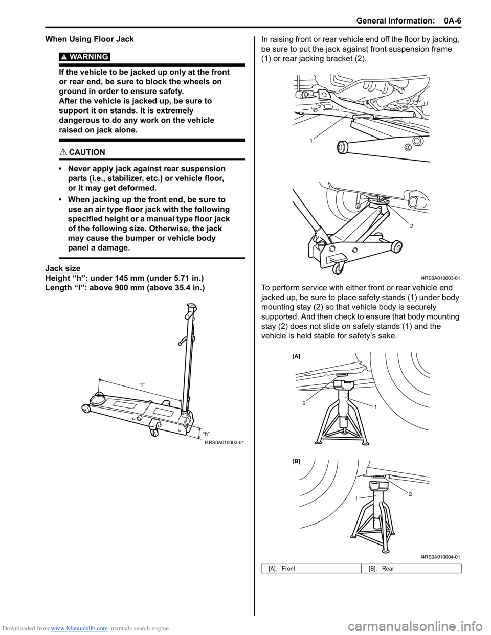
Jack size
Height “h”: under 145 mm (under 5.71 in.)
Length “l”: above 900 mm (above 35.4 in.) In raising front or rear vehicl
e end off the floor by jacking,
be sure to put the jack a gainst front suspension frame
(1) or rear jacking bracket (2).
To perform service with either front or rear vehicle end
jacked up, be sure to place safety stands (1) under body
mounting stay (2) so that vehicle body is securely
supported. And then check to ensure that body mounting
stay (2) does not slide on safety stands (1) and the
vehicle is held stable for safety’s sake.
“h”
“l”
I4RS0A010002-01
[A]: Front
[B]: Rear
2
1
I4RS0A010003-01
1
1
2
2
[B] [A]
I4RS0A010004-01
Page 342 of 1496
Downloaded from www.Manualslib.com manuals search engine 1D-57 Engine Mechanical:
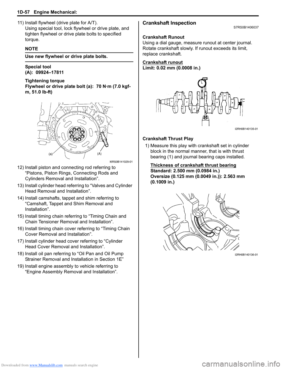
11) Install flywheel (drive plate for A/T).Using special tool, lock flyw heel or drive plate, and
tighten flywheel or drive plate bolts to specified
torque.
NOTE
Use new flywheel or drive plate bolts.
Special tool
(A): 09924–17811
Tightening torque
Flywheel or drive plate bolt (a): 70 N·m (7.0 kgf-
m, 51.0 lb-ft)
12) Install piston and connecting rod referring to “Pistons, Piston Rings, Connecting Rods and
Cylinders Removal and Installation”.
13) Install cylinder head referring to “Valves and Cylinder Head Removal and Installation”.
14) Install camshafts, tappet and shim referring to “Camshaft, Tappet and Shim Removal and
Installation”.
15) Install timing chain referring to “Timing Chain and Chain Tensioner Removal and Installation”.
16) Install timing chain cover referring to “Timing Chain Cover Removal and Installation”.
17) Install cylinder head cover referring to “Cylinder Head Cover Removal and Installation”.
18) Install oil pan referring to “Oil Pan and Oil Pump
Strainer Removal and Installation in Section 1E”
19) Install engine assembly to vehicle referring to “Engine Assembly Removal and Installation”.
Crankshaft InspectionS7RS0B1406037
Crankshaft Runout
Using a dial gauge, measure runout at center journal.
Rotate crankshaft slowly. If runout exceeds its limit,
replace crankshaft.
Crankshaft runout
Limit: 0.02 mm (0.0008 in.)
Crankshaft Thrust Play
1) Measure this play with crankshaft set in cylinder block in the normal manner, that is with thrust
bearing (1) and journal bearing caps installed.
Thickness of crankshaft thrust bearing
Standard: 2.500 mm (0.0984 in.)
Oversize (0.125 mm (0.0049 in.)): 2.563 mm
(0.1009 in.)
I6RS0B141029-01
I2RH0B140135-01
I2RH0B140136-01
Page 468 of 1496
Downloaded from www.Manualslib.com manuals search engine 2D-1 Wheels and Tires:
Suspension
Wheels and Tires
Precautions
Precaution for Emergency Flat Tire Repair KitS7RS0B2400001
WARNING!
Flat tire repair sealant including in kit is
harmful. Be sure to observe the following.
Otherwise, your health may be ruined.
• If swallowed, get medical attention immediately.
• Keep out of reach of children.
• Select place where there is good ventilation for this work.
• If it enters eye or contacts skin, wash thoroughly with water. If anything
abnormal still rema ins, get medical
attention immediately.
• Do not discard tire containing sealant as it is. Make sure to remove sealant from tire,
referring to “Tire Repair for Emergency
Repaired-Tire with Sealant”.
• Dispose of sealant as waste oil.
CAUTION!
• When tire repaired with Emergency Flat Tire Repair Kit is brought in, remove flat
tire repair sealant from tire and repair flat
tire referring to “Tire Repair for Emergency
Repaired-Tire with Sealant”.
• Sealant expiration date is printed on bottle label. if it expires, sealant should be
replaced with a new one to ensure
emergency flat tire repair.
General Description
Tires DescriptionS7RS0B2401001
The tire is of tubeless type. The tire is designed to
operate satisfactorily with loads up to the full rated load
capacity when inflated to the recommended inflation
pressures.
Correct tire pressures and driving habits have an
important influence on tire life. Heavy cornering,
excessively rapid acceleration, and unnecessary sharp
braking increase tire wear.
Tire Placard
The “Tire Placard” is located on the left or right door lock
pillar and should be referred to tire information.
The placard lists the maximum load, tire size and cold
tire pressure where applicable.
NOTE
Whether rim size and/or maximum load are
listed or not depends on regulations of each
country.
Inflation of Tires
The pressure recommended for any model is carefully
calculated to give a satisfacto ry ride, stability, steering,
tread wear, tire life and resistance to bruises.
Tire pressure, with tires cold, (after vehicle has set for 3
hours or more, or driven less than one mile) should be
checked monthly or before any extended trip. Set to the
specifications on the “Tire Placard” located on the left
door lock pillar.
It is normal for tire pressure to increase when the tires
become hot during driving.
Do not bleed or reduce tire pressure after driving.
Bleeding reduces the “Cold Inflation Pressure”.
Higher than recommended pressure can cause:
• Hard ride
• Tire bruising or carcass damage
• Rapid tread wear at center of tire
Unequal pressure on same axle can cause:
• Uneven braking
• Steering lead
• Reduced handling
• Swerve on acceleration
Page 469 of 1496

Downloaded from www.Manualslib.com manuals search engine Wheels and Tires: 2D-2
Lower than recommended pressure can cause:
• Tire squeal on turns
• Hard Steering
• Rapid and uneven wear on the edges of the tread
• Tire rim bruises and rupture
• Tire cord breakage
• High tire temperature
• Reduced handling
• High fuel consumption
Replacement Tires
When replacement is necessary, the original equipment
type tire should be used. Refer to the Tire Placard.
Replacement tires should be of the same size, load
range and construction as those originally on the vehicle.
Use of any other size or type tire may affect ride,
handling, speedometer / odometer calibration, vehicle
ground clearance and tire or snow chain clearance to the
body and chassis.
It is recommended that new tires be installed in pairs on
the same axle. If necessary to replace only one tire, it
should be paired with the tire having the most tread, to
equalize braking traction.
WARNING!
Do not mix different types of tires on the
same vehicle such as radial, bias and bias-
belted tires except in emergencies, because
handling may be seriously affected and may
result in loss of control.
The metric term for tire infl ation pressure is the kilo
pascal (kPa). Tire pressures is usually printed in both
kPa and kgf/cm
2 on the “Tire Placard”.
Metric tire gauges are available from tool suppliers.
The chart, shown the table, converts commonly used
inflation pressures from kPa to kgf/cm
2 and psi.
Wheels DescriptionS7RS0B2401002
Wheel Maintenance
Wheel repairs that use welding, heating, or peening are
not approved. All damaged wheels should be replaced.
Replacement Wheels
Wheels must be replaced if they are bent, dented, have
excessive lateral or radial runout, air leak through welds,
have elongated bolt holes, if lug wheel bolts won’t stay
tight, or if they are heavily rusted. Wheels with greater
runout than shown in the following may cause
objectional vibrations.
Replacement wheels must be equivalent to the original
equipment wheels in load capacity, diameter, rim with
offset and mounting configuration. A wheel of improper
size or type may affect wheel and bearing life, brake
cooling, speedometer / odometer calibration, vehicle
ground clearance and tire clearance to body and
chassis.
How to Measure Wheel Runout
To measure the wheel runout, it is necessary to use an
accurate dial indicator. The tire may be on or off the
wheel. The wheel should be installed to the wheel
balancer of the like for proper measurement.
Take measurements of both lateral runout “a” and radial
runout “b” at both inside an d outside of the rim flange.
With the dial indicator set in place securely, turn the
wheel one full revolution slowly and record every reading
of the indicator.
When the measured runout exceeds the specification
and correction by the balancer adjustment is impossible,
replace the wheel. If the reading is affected by welding,
paint or scratch, it should be ignored.
Lateral runout limit “a”
: 0.3 mm (0.012 in.)
Radial runout limit “b”
: 0.3 mm (0.012 in.)
kPa kgf/cm2psi
Conversion: 1 psi =
6.895 kPa 1 kgf/cm
2 =
98.066 kPa 160 1.6 23
180 1.8 26
200 2.0 29
220 2.2 32
240 2.4 35
260 2.6 38
280 2.8 41
300 3.0 44
I4RS0A240001-01
Page 470 of 1496
Downloaded from www.Manualslib.com manuals search engine 2D-3 Wheels and Tires:
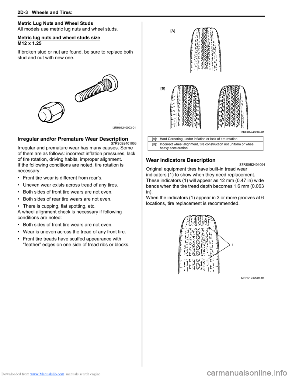
Metric Lug Nuts and Wheel Studs
All models use metric lug nuts and wheel studs.
Metric lug nuts and wheel studs size
M12 x 1.25
If broken stud or nut are found, be sure to replace both
stud and nut with new one.
Irregular and/or Premature Wear DescriptionS7RS0B2401003
Irregular and premature wear has many causes. Some
of them are as follows: incorrect inflation pressures, lack
of tire rotation, driving habits, improper alignment.
If the following conditions are noted, tire rotation is
necessary:
• Front tire wear is different from rear’s.
• Uneven wear exists across tread of any tires.
• Both sides of front tire wears are not even.
• Both sides of rear tire wears are not even.
• There is cupping, flat spotting, etc.
A wheel alignment check is necessary if following
conditions are noted:
• Both sides of front tire wears are not even.
• Wear is uneven across the tread of any front tire.
• Front tire treads have scuffed appearance with “feather” edges on one side of tread ribs or blocks.
Wear Indicators DescriptionS7RS0B2401004
Original equipment tires have built-in tread wear
indicators (1) to show when they need replacement.
These indicators (1) will app ear as 12 mm (0.47 in) wide
bands when the tire tread depth becomes 1.6 mm (0.063
in).
When the indicators (1) appear in 3 or more grooves at 6
locations, tire replacement is recommended.
I2RH01240003-01
[A]: Hard Cornering, under inflation or lack of tire rotation
[B]: Incorrect wheel alignment, tire construction not uniform or wheel heavy acceleration
I3RH0A240002-01
I2RH01240005-01
Page 476 of 1496

Downloaded from www.Manualslib.com manuals search engine 2D-9 Wheels and Tires:
2) Check tire if it can be repaired, referring to “Tire
Repair”. If it cannot be repaired, replace it with new
one.
3) Replace valve core of flat tire with new one if tire is reused after repairing.CAUTION!
Be sure to use new valve core. Otherwise, air
leak may occur due to sealant attached to
valve core.
4) Install tire to ri m of wheel, check that there is no air
leakage and adjust it to specified pressure shown on
tire placard.
Specifications
Wheels and Tires SpecificationsS7RS0B2407001
Tire size (Standard)
: 195/50R16 87V
Wheel size (Standard)
: 16x 6 J
Tightening torque
Wheel nut: 85 N·m (8.5 kgf-m, 61.5 lb-ft)
NOTE
• Tire inflation pressure should be checked when tires are cool.
• Specified tire inflation pressure should be found on tire placard or in owner’s manual which came
with the vehicle.
Tightening Torque SpecificationsS7RS0B2407002
Reference:
For the tightening torque of fastener not specified in this section, refer to “Fasteners Information in Section 0A”.
Fastening part
Tightening torque
Note
N ⋅mkgf-mlb-ft
Wheel nut 858.5 61.5 �) / �)