2005 SUZUKI SWIFT freeze
[x] Cancel search: freezePage 35 of 1496
Downloaded from www.Manualslib.com manuals search engine Maintenance and Lubrication: 0B-5
4) Screw new filter on oil filter stand by hand until the filter O-ring contacts mounting surface.
CAUTION!
To tighten oil filter prop erly, it is important to
accurately identify the position at which filter
O-ring first contacts mounting surface.
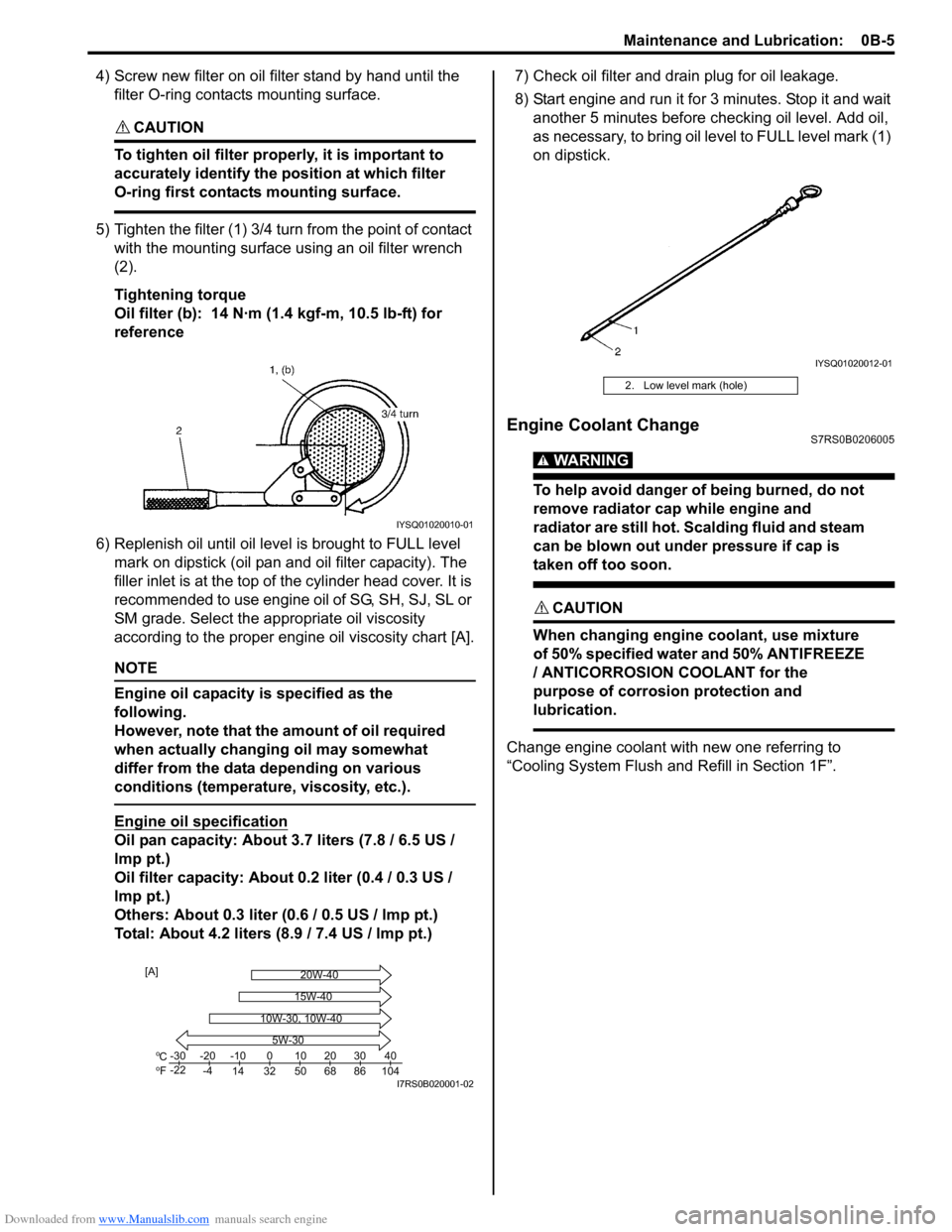
5) Tighten the filter (1) 3/4 tu rn from the point of contact
with the mounting surface using an oil filter wrench
(2).
Tightening torque
Oil filter (b): 14 N·m (1 .4 kgf-m, 10.5 lb-ft) for
reference
6) Replenish oil until oil leve l is brought to FULL level
mark on dipstick (oil pan and oil filter capacity). The
filler inlet is at the top of the cylinder head cover. It is
recommended to use engine oil of SG, SH, SJ, SL or
SM grade. Select the appropriate oil viscosity
according to the proper engine oil viscosity chart [A].
NOTE
Engine oil capacity is specified as the
following.
However, note that the amount of oil required
when actually changing oil may somewhat
differ from the data depending on various
conditions (temperature, viscosity, etc.).
Engine oil specification
Oil pan capacity: About 3.7 liters (7.8 / 6.5 US /
lmp pt.)
Oil filter capacity: About 0.2 liter (0.4 / 0.3 US /
lmp pt.)
Others: About 0.3 liter (0 .6 / 0.5 US / lmp pt.)
Total: About 4.2 liters (8.9 / 7.4 US / lmp pt.) 7) Check oil filter and drain plug for oil leakage.
8) Start engine and run it for 3 minutes. Stop it and wait
another 5 minutes before checking oil level. Add oil,
as necessary, to bring oil le vel to FULL level mark (1)
on dipstick.
Engine Coolant ChangeS7RS0B0206005
WARNING!
To help avoid danger of being burned, do not
remove radiator cap while engine and
radiator are still hot. Scalding fluid and steam
can be blown out under pressure if cap is
taken off too soon.
CAUTION!
When changing engine coolant, use mixture
of 50% specified water and 50% ANTIFREEZE
/ ANTICORROSION COOLANT for the
purpose of corrosion protection and
lubrication.
Change engine coolant with new one referring to
“Cooling System Flush and Refill in Section 1F”.
IYSQ01020010-01
Co
Fo-30
-22 -20
-4 -10
14 32 50 68 86 104 010203040
5W-30
20W-40
15W-40
10W-30, 10W-40
[A]
I7RS0B020001-02
2. Low level mark (hole)
IYSQ01020012-01
Page 43 of 1496
Downloaded from www.Manualslib.com manuals search engine Maintenance and Lubrication: 0B-13
Brake
Foot brake
Check the following:
• that brake pedal has proper travel,
• that brake works properly,
• that it is free from noise,
• that vehicle does not pull to one side when brake is applied.
• and that brake do not drag.
Parking brake
Check that lever has proper travel.
WARNING!
With vehicle parked on a fairly steep slope,
make sure nothing is in the way downhill to
avoid any personal injury or property
damage. Be prepared to apply regular brake
quickly even if vehicle should start to move.
Check to ensure that parking brake is fully effective
when the vehicle is stopped on the safe slope and brake
lever is pulled all the way.
Steering
• Check to ensure that steering wheel is free from instability, or abnormally heavy feeling. • Check that the vehicle does not wander or pull to one
side.
Engine
• Check that engine responds readily at all speeds.
• Check that engine is free from abnormal noise and abnormal vibration.
Body, Wheels and Power Transmitting System
Check that body, wheels and power transmitting system
are free from abnormal noise and abnormal vibration or
any other abnormal condition.
Meters and Gauge
Check that speedometer, odometer, fuel meter,
temperature gauge, etc. are operating accurately.
Lights
Check that all lights operate properly.
Windshield Defroster
Periodically check that ai r comes out from defroster
outlet when operating heater or air conditioning.
Set mode control lever to defroster position and fan
switch lever to “HI” position for this check.
Specifications
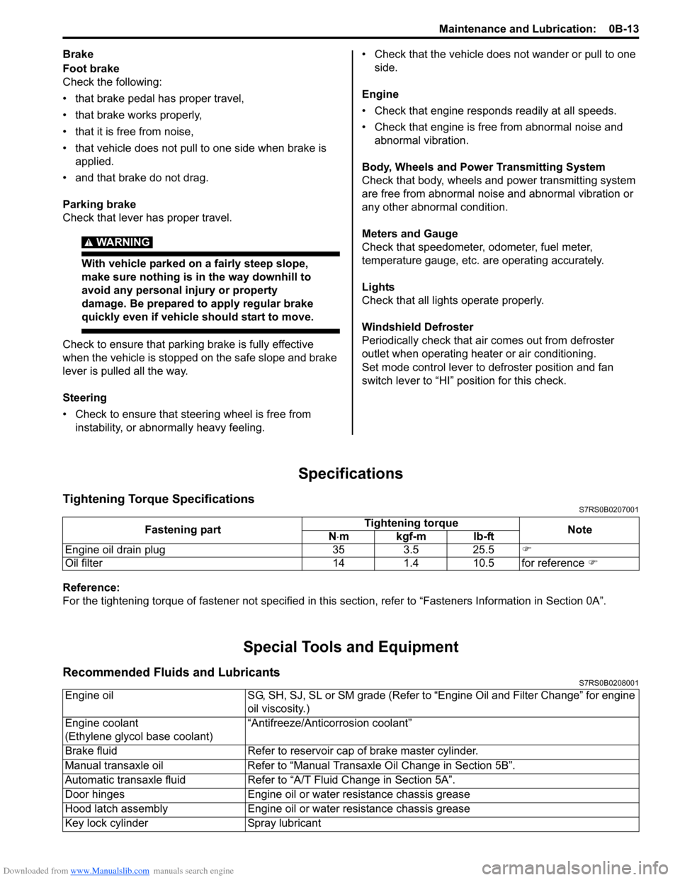
Tightening Torque SpecificationsS7RS0B0207001
Reference:
For the tightening torque of fastener not specified in this section, refer to “Fasteners Information in Section 0A”.
Special Tools and Equipment
Recommended Fluids and LubricantsS7RS0B0208001
Fastening part Tightening torque
Note
N ⋅mkgf-mlb-ft
Engine oil drain plug 35 3.5 25.5 �)
Oil filter 14 1.4 10.5 for reference �)
Engine oilSG, SH, SJ, SL or SM grade (Refer to “Engine Oil and Filter Change” for engine
oil viscosity.)
Engine coolant
(Ethylene glycol base coolant) “Antifreeze/Antico
rrosion coolant”
Brake fluid Refer to reservoir cap of brake master cylinder.
Manual transaxle oil Refer to “Manual Transaxle Oil Change in Section 5B”.
Automatic transaxle fluid Refer to “A/T Fluid Change in Section 5A”.
Door hinges Engine oil or water resistance chassis grease
Hood latch assembly Engine oil or water resistance chassis grease
Key lock cylinder Spray lubricant
Page 51 of 1496
Downloaded from www.Manualslib.com manuals search engine Engine General Information and Diagnosis: 1A-1
Engine
Engine General Information and Diagnosis
Precautions
Precautions on Engine ServiceS7RS0B1100001
CAUTION!
The following information on engine service
should be noted carefully, as it is important in
preventing damage, and in contributing to
reliable engine performance.
• When raising or supporting engine for any reason, do
not use a jack under oil pan. Due to small clearance
between oil pan and oil pump strainer, jacking against
oil pan may cause it to be bent against strainer,
resulting in damaged oil pick-up unit.
• It should be kept in mind , while working on engine,
that 12-volt electrical syste m is capable of violent and
damaging short circuits.
When performing any work where electrical terminals
can be grounded, ground cable of the battery should
be disconnected at battery.
• Any time the air cleaner, throttle body or intake manifold is removed, the intake opening should be
covered. This will protect against accidental entrance
of foreign material which could follow intake passage
into cylinder and cause extensive damage when
engine is started.
Precaution on On-Board Diagnostic (OBD)
System
S7RS0B1100005
There are two types of On -Board Diagnostic (OBD)
system, Euro OBD system and non-Euro-OBD system,
depending on the vehicle specification.
As the diagnosis function is different between these two
types, be sure to fully understand the OBD system
referring to “On-Board Diagnostic System Description”.
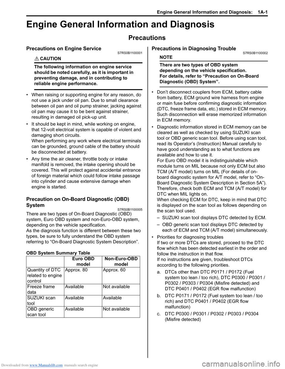
OBD System Summary Table
Precautions in Diagnosing TroubleS7RS0B1100002
NOTE
There are two types of OBD system
depending on the vehicle specification.
For details, refer to “Precaution on On-Board
Diagnostic (OBD) System”.
• Don’t disconnect couplers from ECM, battery cable
from battery, ECM ground wire harness from engine
or main fuse before confirming diagnostic information
(DTC, freeze frame data, etc.) stored in ECM memory.
Such disconnection will erase memorized information
in ECM memory.
• Diagnostic information stored in ECM memory can be cleared as well as checke d by using SUZUKI scan
tool or OBD generic scan tool. Before using scan tool,
read its Operator’s (Instruction) Manual carefully to
have good understanding as to what functions are
available and how to use it.
For Euro OBD model it is indistinguishable which
module turns on MIL because not only ECM but also
TCM (A/T model) turns on MIL (For details of on-
board diagnostic system for A/T model, refer to “On-
Board Diagnostic System Description in Section 5A”).
Therefore, check both ECM and TCM (A/T model) for
DTC when MIL lights on.
When checking ECM for DTC, keep in mind that DTC
is displayed on the scan tool as follows depending on
the scan tool used.
– SUZUKI scan tool displays DTC detected by ECM.
– OBD generic scan tool displays DTC detected by each of ECM and TCM (A/T model) simultaneously.
• Priorities for diagnosing troubles If two or more DTCs are stored, proceed to the DTC
flow which has been detected earliest in the order and
follow the instructi on in that flow.
If no instructions are given, troubleshoot DTCs
according to the following priorities.
a. DTCs other than DTC P0171 / P0172 (Fuel system too lean / too rich), DTC P0300 / P0301 /
P0302 / P0303 / P0304 (Misfire detected) and
DTC P0401 / P0402 (EGR flow malfunction)
b. DTC P0171 / P0172 (Fuel system too lean / too rich) and DTC P0401 / P0402 (EGR flow
malfunction)
c. DTC P0300 / P0301 / P0302 / P0303 / P0304 (Misfire detected)
Euro OBD
model Non-Euro-OBD
model
Quantity of DTC
related to engine
control Approx. 80 Approx. 60
Freeze frame
data Available Not available
SUZUKI scan
tool Available Available
OBD generic
scan tool Available Not available
Page 53 of 1496
Downloaded from www.Manualslib.com manuals search engine Engine General Information and Diagnosis: 1A-3
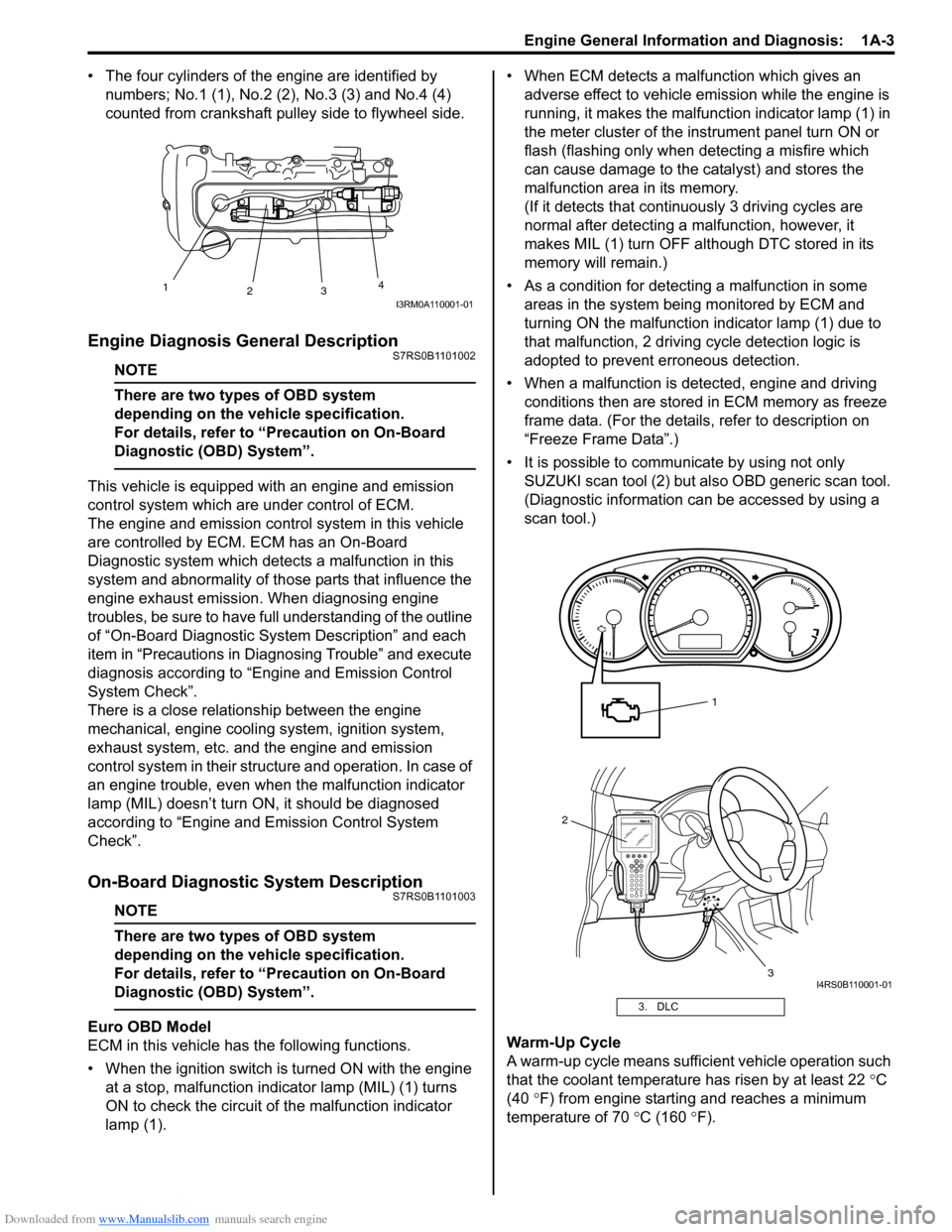
• The four cylinders of the engine are identified by numbers; No.1 (1), No.2 (2 ), No.3 (3) and No.4 (4)
counted from crankshaft pulley side to flywheel side.
Engine Diagnosis General DescriptionS7RS0B1101002
NOTE
There are two types of OBD system
depending on the vehicle specification.
For details, refer to “Precaution on On-Board
Diagnostic (OBD) System”.
This vehicle is equipped with an engine and emission
control system which are under control of ECM.
The engine and emission control system in this vehicle
are controlled by ECM. ECM has an On-Board
Diagnostic system which detects a malfunction in this
system and abnormality of those parts that influence the
engine exhaust emission. When diagnosing engine
troubles, be sure to have full understanding of the outline
of “On-Board Diagnostic System Description” and each
item in “Precautions in Diagnosing Trouble” and execute
diagnosis according to “Engine and Emission Control
System Check”.
There is a close relationship between the engine
mechanical, engine cooling system, ignition system,
exhaust system, etc. and the engine and emission
control system in their structure and operation. In case of
an engine trouble, even when the malfunction indicator
lamp (MIL) doesn’t turn ON, it should be diagnosed
according to “Engine and Emission Control System
Check”.
On-Board Diagnostic System DescriptionS7RS0B1101003
NOTE
There are two types of OBD system
depending on the vehicle specification.
For details, refer to “Precaution on On-Board
Diagnostic (OBD) System”.
Euro OBD Model
ECM in this vehicle has the following functions.
• When the ignition switch is turned ON with the engine at a stop, malfunction indicator lamp (MIL) (1) turns
ON to check the circuit of the malfunction indicator
lamp (1). • When ECM detects a malfunction which gives an
adverse effect to vehicle emission while the engine is
running, it makes the malfunction indicator lamp (1) in
the meter cluster of the inst rument panel turn ON or
flash (flashing only when detecting a misfire which
can cause damage to the catalyst) and stores the
malfunction area in its memory.
(If it detects that contin uously 3 driving cycles are
normal after detecting a malfunction, however, it
makes MIL (1) turn OFF although DTC stored in its
memory will remain.)
• As a condition for detecting a malfunction in some areas in the system being monitored by ECM and
turning ON the malfunction indicator lamp (1) due to
that malfunction, 2 driving cycle detection logic is
adopted to prevent erroneous detection.
• When a malfunction is detected, engine and driving conditions then are stored in ECM memory as freeze
frame data. (For the details, refer to description on
“Freeze Frame Data”.)
• It is possible to communicate by using not only SUZUKI scan tool (2) but also OBD generic scan tool.
(Diagnostic information can be accessed by using a
scan tool.)
Warm-Up Cycle
A warm-up cycle means sufficie nt vehicle operation such
that the coolant temperature has risen by at least 22 °C
(40 °F) from engine starting and reaches a minimum
temperature of 70 °C (160 ° F).
1
23 4
I3RM0A110001-01
3. DLC
2
3
1
I4RS0B110001-01
Page 54 of 1496
Downloaded from www.Manualslib.com manuals search engine 1A-4 Engine General Information and Diagnosis:
Driving Cycle
A “Driving Cycle” consists of engine startup and engine
shutoff.
2 Driving Cycle Detection Logic
The malfunction detected in the first driving cycle is
stored in ECM memory (in t he form of pending DTC) but
the malfunction indicator lamp does not light at this time.
It lights up at the second detection of same malfunction
also in the next driving cycle.
Pending DTC
Pending DTC means a DTC detected and stored
temporarily at 1 driving cycle of the DTC which is
detected in the 2 driving cycle detection logic.
Freeze Frame Data
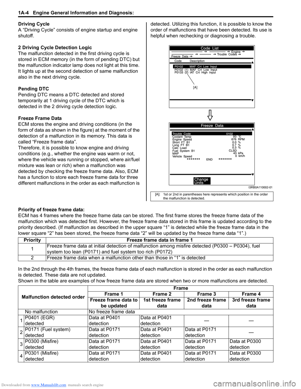
ECM stores the engine and driving conditions (in the
form of data as shown in the figure) at the moment of the
detection of a malfunction in its memory. This data is
called “Freeze frame data”.
Therefore, it is possible to know engine and driving
conditions (e.g., whether the engine was warm or not,
where the vehicle was running or stopped, where air/fuel
mixture was lean or rich) when a malfunction was
detected by checking the freeze frame data. Also, ECM
has a function to store each freeze frame data for three
different malfunctions in the order as each malfunction is detected. Utilizing this function,
it is possible to know the
order of malfunctions that ha ve been detected. Its use is
helpful when rechecking or diagnosing a trouble.
Priority of freeze frame data:
ECM has 4 frames where the freeze frame data can be stor ed. The first frame stores the freeze frame data of the
malfunction which was detected first. Howe ver, the freeze frame data stored in this frame is updated according to the
priority described. (If malfunction as described in the upper square “1” is detected while the freeze frame data in the
lower square “2” has been stored, the freeze frame data “2” will be updated by the freeze frame data “1”.)
In the 2nd through the 4th frames, the freeze frame data of each malfunction is stored in the order as each malfunction
is detected. These data are not updated.
Shown in the table are examples of how freeze frame data are stored when two or more malfunctions are detected.
[A]: 1st or 2nd in parentheses here represents which position in the order
the malfunction is detected.
[A]
I3RB0A110002-01
Priority Freeze frame data in frame 1
1 Freeze frame data at initial detection of malfuncti
on among misfire detected (P0300 – P0304), fuel
system too lean (P0171) and fuel system too rich (P0172)
2 Freeze frame data when a malfunctio n other than those in “1” is detected
Malfunction detected order Frame
Frame 1 Frame 2 Frame 3 Frame 4
Freeze frame data to be updated 1st freeze frame
data 2nd freeze frame
data 3rd freeze frame
data
No malfunction No freeze frame data
1 P0401 (EGR)
detected Data at P0401
detectionData at P0401
detection
——
2 P0171 (Fuel system)
detected Data at P0171
detectionData at P0401
detectionData at P0171
detection
—
3 P0300 (Misfire)
detected Data at P0171
detectionData at P0401
detectionData at P0171
detectionData at P0300
detection
4 P0301 (Misfire)
detected Data at P0171
detectionData at P0401
detectionData at P0171
detectionData at P0300
detection
Page 55 of 1496
Downloaded from www.Manualslib.com manuals search engine Engine General Information and Diagnosis: 1A-5
Freeze frame data clearance:
The freeze frame data is cleared at the same time as
clearance of DTC.
Non-Euro-OBD
ECM diagnosis troubles which may occur in the area
including the following parts w hen the ignition switch is
ON and the engine is running, and indicates the result by
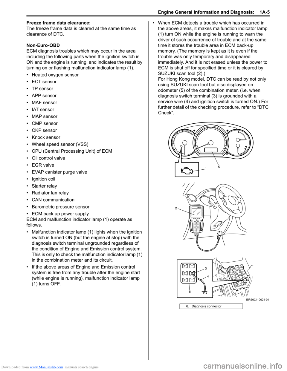
turning on or flashing malfunction indicator lamp (1).
• Heated oxygen sensor
• ECT sensor
•TP sensor
• APP sensor
• MAF sensor
• IAT sensor
• MAP sensor
• CMP sensor
• CKP sensor
• Knock sensor
• Wheel speed sensor (VSS)
• CPU (Central Processing Unit) of ECM
• Oil control valve
• EGR valve
• EVAP canister purge valve
• Ignition coil
• Starter relay
• Radiator fan relay
• CAN communication
• Barometric pressure sensor
• ECM back up power supply
ECM and malfunction indicator lamp (1) operate as
follows.
• Malfunction indicator lamp (1) lights when the ignition switch is turned ON (but t he engine at stop) with the
diagnosis switch terminal ungrounded regardless of
the condition of Engine and Emission control system.
This is only to check the ma lfunction indicator lamp (1)
in the combination meter and its circuit.
• If the above areas of Engine and Emission control system is free from any trouble after the engine start
(while engine is running), malfunction indicator lamp
(1) turns OFF. • When ECM detects a trouble which has occurred in
the above areas, it makes malfunction indicator lamp
(1) turn ON while the engi ne is running to warn the
driver of such occurrence of trouble and at the same
time it stores the trouble area in ECM back-up
memory. (The memory is kept as it is even if the
trouble was only temporary and disappeared
immediately. And it is not erased unless the power to
ECM is shut off for specified time or it is cleared by
SUZUKI scan tool (2).)
For Hong Kong model, DTC can be read by not only
using SUZUKI scan tool but also displayed on
odometer (5) of the combination meter. (i.e. when
diagnosis switch terminal (3) is grounded with a
service wire (4) and ignition switch is turned ON.) For
further detail of the checking procedure, refer to “DTC
Check”.
6. Diagnosis connector
2
1
6 3
5
4
I5RS0C110021-01
Page 72 of 1496

Downloaded from www.Manualslib.com manuals search engine 1A-22 Engine General Information and Diagnosis:
Diagnostic Information and Procedures
Engine and Emission Control System CheckS7RS0B1104001
Refer to the following items for the details of each step.Step Action Yes No 1 �) Customer complaint analysis
1) Perform customer complaint analysis referring to “Customer Complaint Analysis”.
Was customer complaint analysis performed? Go to Step 2. Perform customer
complaint analysis.
2 �) DTC / Freeze frame data check, record and clearance
1) Check for DTC (including pending DTC) referring to “DTC / Freeze Frame Data Check, Record and
Clearance”.
Is there any DTC(s)? Print DTC and freeze
frame data or write them
down and clear them by
referring to “DTC
Clearance”, and go to
St ep 3 .Go to Step 4.
3 �) Visual inspection
1) Perform visual inspection referring to “Visual Inspection”.
Is there any faulty condition? Repair or replace
malfunction part, and go
to Step 11.
Go to Step 5.
4 �) Visual inspection
1) Perform visual inspection referring to “Visual Inspection”.
Is there any faulty condition? Repair or replace
malfunction part, and go
to Step 11.
Go to Step 8.
5 �) Trouble symptom confirmation
1) Confirm trouble symptom referring to “Trouble Symptom Confirmation”.
Is trouble symptom identified? Go to Step 6.
Go to Step 7.
6 �) Rechecking and record of DTC / Freeze frame data
1) Recheck for DTC and freeze frame data referring to “DTC Check”.
Is there any DTC(s)? Go to Step 9.
Go to Step 8.
7 �) Rechecking and record of DTC / Freeze frame data
1) Recheck for DTC and freeze frame data referring to “DTC Check”.
Is there any DTC(s)? Go to Step 9.
Go to Step 10.
8 �) Engine basic inspection and engine symptom
diagnosis
1) Check and repair according to “Engine Basic Inspection”
and “Engine Symptom Diagnosis”.
Are check and repair complete? Go to Step 11. Check and repair
malfunction part(s), and
go to Step 11.
9 �) Troubleshooting for DTC
1) Check and repair according to applicable DTC diag. flow.
Are check and repair complete? Go to Step 11. Check and repair
malfunction part(s), and
go to Step 11.
10 �) Intermittent problems check
1) Check for intermittent problems referring to “Intermittent Problems Check”.
Is there any faulty condition? Repair or replace
malfunction part(s), and
go to Step 11.
Go to Step 11.
Page 75 of 1496
Downloaded from www.Manualslib.com manuals search engine Engine General Information and Diagnosis: 1A-25
Step 2: DTC / Freeze Frame Data Check, Record and
Clearance
First, check DTC (including pending DTC), referring to
“DTC Check”. If DTC is indicated, print it and freeze
frame data or write them down and then clear them by
referring to “DTC Clearance”. DTC indicates malfunction
that occurred in the system but does not indicate
whether it exists now or it occurred in the past and the
normal condition has been restored now. To check which
case applies, check the sy mptom in question according
to Step 5 and recheck DTC according to Step 6 and 7.
Attempt to diagnose a trouble based on DTC in this step
only or failure to clear the DTC in this step will lead to
incorrect diagnosis, trouble diagnosis of a normal circuit
or difficulty in troubleshooting.
Step 3 and 4: Visual Inspection
As a preliminary step, be sure to perform visual check of
the items that support proper function of the engine
referring to “Visual Inspection”.
Step 5: Trouble Symptom Confirmation
Based on information obtained in “Step 1: Customer
Complaint Analysis: ” and “Step 2: DTC / Freeze Frame
Data Check, Record and Clearance: ”, confirm trouble
symptoms. Also, reconfirm DTC according to “DTC
Confirmation Procedure” described in each DTC diag.
flow.
Step 6 and 7: Rechecking and Record of DTC /
Freeze Frame Data
Refer to “DTC Check” for checking procedure.
Step 8: Engine Basic Inspection and Engine
Symptom Diagnosis
Perform basic engine check according to “Engine Basic
Inspection” first. When the end of the flow has been
reached, check the parts of the system suspected as a
possible cause referring to “Engine Symptom Diagnosis”
and based on symptoms appearing on the vehicle
(symptoms obtained through steps of customer
complaint analysis, trouble symptom confirmation and/or
basic engine check) and repair or replace faulty parts, if
any.
Step 9: Troubleshooting for DTC (See each DTC
Diag. Flow)
Based on the DTC indicated in Step 6 or 7 and referring
to the applicable DTC diag. flow, locate the cause of the
trouble, namely in a sensor, switch, wire harness,
connector, actuator, ECM or other part and repair or
replace faulty parts. Step 10: Intermittent Problems Check
Check parts where an intermit
tent trouble is easy to
occur (e.g., wire harness, connector, etc.), referring to
“Intermittent and Poor Connec tion Inspection in Section
00” and related circuit of DTC recorded in Step 2.
Step 11: Final Confirmation Test
Confirm that the problem symptom has gone and the
engine is free from any abnormal conditions. If what has
been repaired is re lated to the DTC, clear the DTC once,
perform DTC confirmation procedure and confirm that no
DTC is indicated.
Malfunction Indicator Lamp (MIL) CheckS7RS0B1104002
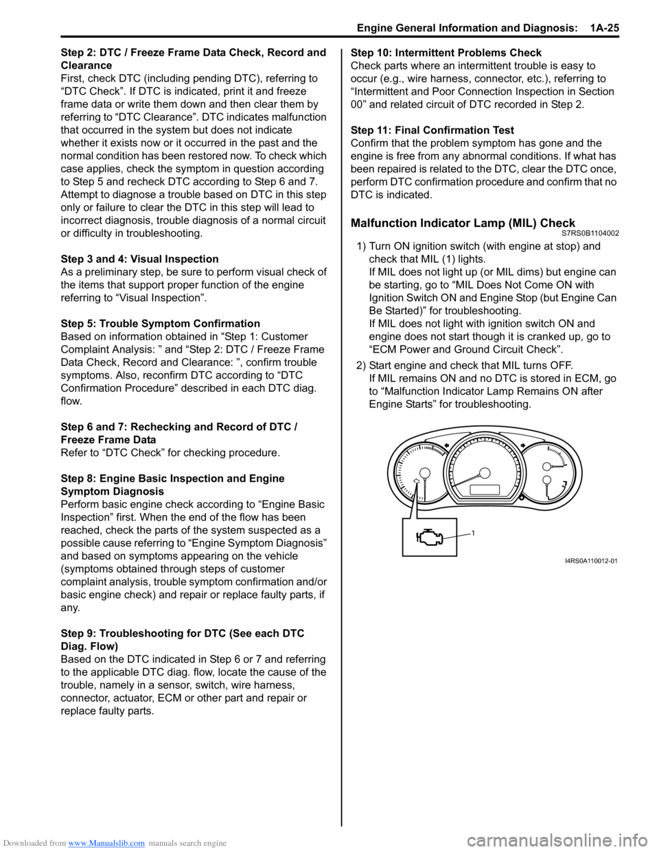
1) Turn ON ignition switch (with engine at stop) and check that MIL (1) lights.
If MIL does not light up (or MIL dims) but engine can
be starting, go to “MIL Does Not Come ON with
Ignition Switch ON and Engine Stop (but Engine Can
Be Started)” for troubleshooting.
If MIL does not light with ignition switch ON and
engine does not start though it is cranked up, go to
“ECM Power and Ground Circuit Check”.
2) Start engine and check that MIL turns OFF. If MIL remains ON and no DTC is stored in ECM, go
to “Malfunction Indicator Lamp Remains ON after
Engine Starts” for troubleshooting.
1
I4RS0A110012-01