2005 SUZUKI SWIFT CD changer
[x] Cancel search: CD changerPage 48 of 1496

Downloaded from www.Manualslib.com manuals search engine 1-iv Table of Contents
Engine Lubrication System.....................1E-1
General Description ............................................. 1E-1
Engine Lubrication Description ........................... 1E-1
Diagnostic Information and Procedures ............ 1E-2 Oil Pressure Check ............................................. 1E-2
Repair Instructions ........... ................................... 1E-3
Heat Exchanger Components ............................. 1E-3
Heat Exchanger On-Vehicle Inspection .............. 1E-4
Heat Exchanger Removal and Installation .......... 1E-4
Oil Pan and Oil Pump Strainer Components....... 1E-5
Oil Pan and Oil Pump Strainer Removal and
Installation ......................................................... 1E-5
Oil Pan and Oil Pump Stra iner Cleaning ............. 1E-7
Oil Pump Components ........................................ 1E-8
Oil Pump Removal and Installation ..................... 1E-8
Oil Pump Disassembly and Reassembly ............ 1E-8
Oil Pump Inspection ............................................ 1E-9
Specifications .... ................................................. 1E-11
Tightening Torque Specifications ...................... 1E-11
Special Tools and Equipmen t ........................... 1E-11
Recommended Service Material ....................... 1E-11
Special Tool ...................................................... 1E-11
Engine Cooling System ..... ...................... 1F-1
General Description .......... ................................... 1F-1
Cooling System Descriptio n ................................ 1F-1
Coolant Description ............................................. 1F-1
Schematic and Routing Diagram ........................ 1F-2 Coolant Circulation .............................................. 1F-2
Diagnostic Information and Procedures ............ 1F-4 Engine Cooling Symptom Diagnosis ................... 1F-4
Repair Instructions ........... ................................... 1F-5
Cooling System Components.............................. 1F-5
Coolant Level Check ........................................... 1F-6
Engine Cooling System Inspection and Cleaning ............................................................ 1F-6
Cooling System Draining.. ................................... 1F-6
Cooling System Flush and Refill ......................... 1F-7
Cooling Water Pipes or Hoses Removal and Installation ......................................................... 1F-7
Thermostat Removal and In stallation.................. 1F-8
Thermostat Inspection......................................... 1F-8
Radiator Cooling Fan Motor On-Vehicle Inspection .......................................................... 1F-9
Radiator Cooling Fan Rela y Inspection............... 1F-9
Radiator Cooling Fan Removal and Installation ....................................................... 1F-10
Radiator On-Vehicle Inspection and Cleaning .. 1F-10
Radiator Removal and Inst allation .................... 1F-10
Water Pump Removal and In stallation .............. 1F-11
Water Pump Inspection ..................................... 1F-11
Specifications .... ................................................. 1F-12
Tightening Torque Specifications ...................... 1F-12
Special Tools and Equipmen t ........................... 1F-12
Recommended Service Material ....................... 1F-12
Fuel System ................... .......................... 1G-1
Precautions.......................................................... 1G-1 Precautions on Fuel System Service ................. 1G-1
General Description ............................................ 1G-1 Fuel System Description .................................... 1G-1
Fuel Delivery System Description ...................... 1G-1
Fuel Pump Description ....................................... 1G-2
Schematic and Routing Diagram ....................... 1G-2 Fuel Delivery System Diag ram........................... 1G-2
Diagnostic Information and Procedures ........... 1G-2 Fuel Pressure Inspection ................................... 1G-2
Fuel Cut Operation Inspection ........................... 1G-3
Repair Instructions ............ ................................. 1G-4
Fuel System Components .................................. 1G-4
Fuel Hose Disconnecting and Reconnecting ..... 1G-5
Fuel Pressure Relief Procedure ......................... 1G-7
Fuel Leakage Check Procedure......................... 1G-7
Fuel Lines On-Vehicle Inspection ...................... 1G-7
Fuel Pipe Removal and Installation.................... 1G-7
Fuel Injector On-Vehicle Inspection ................... 1G-8
Fuel Injector Removal and Installation ............... 1G-8
Fuel Injector Inspection ...................................... 1G-9
Fuel Filler Cap Inspection . ............................... 1G-10
Fuel Tank Inlet Valve Removal and Installation ...................................................... 1G-11
Fuel Tank Inlet Valve Inspection ...................... 1G-12
Fuel Tank Removal and Installation ................. 1G-12
Fuel Tank Inspection ........................................ 1G-13
Fuel Tank Purging Procedure .......................... 1G-14
Fuel Pump On-Vehicle Inspection.................... 1G-14
Fuel Pump Assembly Removal and Installation ...................................................... 1G-14
Main Fuel Level Sensor Removal and Installation ...................................................... 1G-15
Fuel Pump Inspection ...................................... 1G-16
Specifications ..................... ............................... 1G-16
Tightening Torque Specifications ..................... 1G-16
Special Tools and Equipmen t .......................... 1G-17
Special Tool ..................................................... 1G-17
Ignition System .............. .......................... 1H-1
General Description .............................................1H-1
Ignition System Construction ..............................1H-1
Schematic and Routing Diagram ........................1H-2 Ignition System Wiring Circuit Diagram...............1H-2
Component Location ............ ...............................1H-3
Ignition System Components Location................1H-3
Diagnostic Information and Procedures ............1H-4 Ignition System Symptom Diagnosis...................1H-4
Reference Waveform of Ignition System.............1H-4
Ignition System Check ........................................1H-4
Ignition Spark Test ..............................................1H-6
Repair Instructions ............ ..................................1H-6
High-Tension Cord Removal and Installation......1H-6
High-Tension Cord Inspection.............................1H-7
Spark Plug Removal and Installation ..................1H-7
Spark Plug Inspection .........................................1H-7
Ignition Coil Assembly (Including ignitor)
Removal and Installation ...................................1H-8
Ignition Coil Assembly (Including ignitor)
Inspection ..........................................................1H-8
Page 353 of 1496

Downloaded from www.Manualslib.com manuals search engine Engine Lubrication System: 1E-1
Engine
Engine Lubrication System
General Description
Engine Lubrication DescriptionS7RS0B1501001
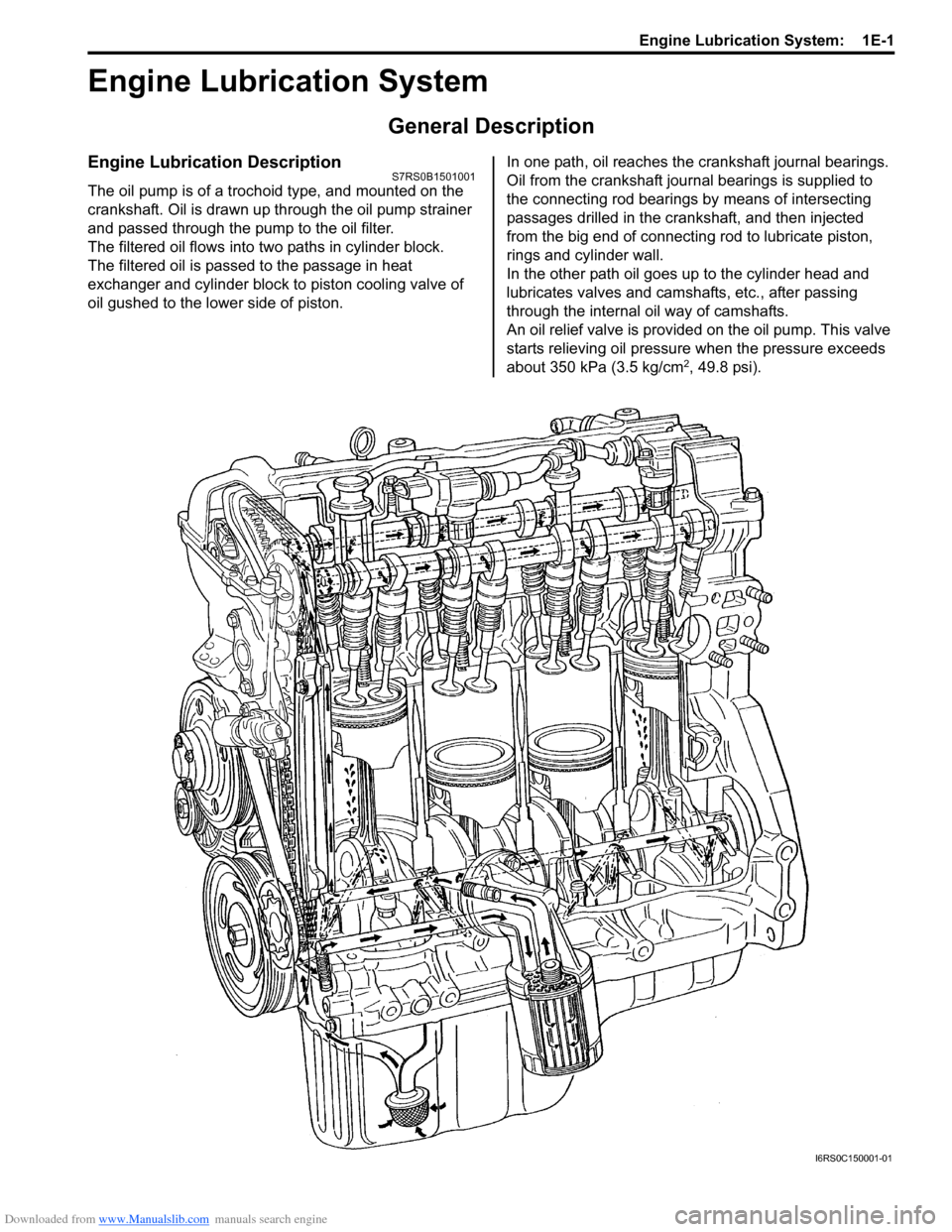
The oil pump is of a trochoid type, and mounted on the
crankshaft. Oil is drawn up through the oil pump strainer
and passed through the pump to the oil filter.
The filtered oil flows into two paths in cylinder block.
The filtered oil is passed to the passage in heat
exchanger and cylinder block to piston cooling valve of
oil gushed to the lower side of piston. In one path, oil reaches the crankshaft journal bearings.
Oil from the crankshaft journal bearings is supplied to
the connecting rod bearings by means of intersecting
passages drilled in the cran
kshaft, and then injected
from the big end of connecting rod to lubricate piston,
rings and cylinder wall.
In the other path oil goes up to the cylinder head and
lubricates valves and camshafts, etc., after passing
through the internal oil way of camshafts.
An oil relief valve is provided on the oil pump. This valve
starts relieving oil pressure when the pressure exceeds
about 350 kPa (3.5 kg/cm
2, 49.8 psi).
I6RS0C150001-01
Page 355 of 1496

Downloaded from www.Manualslib.com manuals search engine Engine Lubrication System: 1E-3
6) Start engine and warm engine up to normal operating temperature.
NOTE
Be sure to shift transaxle gear shift lever in
“Neutral” (shift select lever in “P” range for
A/T vehicle), set parking brake and block
drive wheels.
7) After warming up, raise engine speed to 4,000 r/min. and measure oil pressure.
Oil pressure specification
More than 270 kPa (2.7 kg/cm2, 39.8 psi) at 4,000
r/min. (rpm)
8) After checking oil pressure, stop engine and remove oil pressure gauge and attachment.
9) Before reinstalling oil pressure switch (2), be sure to
wrap its screw threads with sealing tape (1) and
tighten switch to specified torque.
NOTE
If sealing tape edge is bulged out from screw
threads of switch, cut it off.
Tightening torque
Oil pressure switch (a): 13 N·m (1.3 kgf-m, 9.5
lb-ft) 10) Start engine and check oil pressure switch for oil
leakage. If oil leakage is found, repair it.
11) Connect oil pressure switch coupler (1).
Repair Instructions
Heat Exchanger ComponentsS7RS0B1506001
I2RH0B150005-01
I2RH0B150006-01
3
4
5
7
6
(a)
2
1
I6RS0B151001-02
1. Heat exchanger inlet No. 1 hose 4. Gasket7. O-ring
: Apply engine oil.
2. Heat exchanger outlet No. 1 hose 5. Heat exchanger stand bolt : 22 N⋅m (2.2 kgf-m, 16.0 lb-ft)
3. Heat exchanger 6. Oil filter adapter case : Do not reuse.
Page 356 of 1496

Downloaded from www.Manualslib.com manuals search engine 1E-4 Engine Lubrication System:
Heat Exchanger On-Vehicle InspectionS7RS0B1506002
• Check heat exchanger for deformation wear or damage.
• Check heat exchanger for coolant leakage and oil leakage.
If any malcondition is found, replace O-ring, stand bolt
gasket and/or heat exchanger.
Heat Exchanger Removal and InstallationS7RS0B1506003
Removal
1) Drain engine oil by removing drain plug.
2) Drain coolant referring to “Cooling System Draining in Section 1F”.
3) Remove exhaust manifold referring to “Exhaust Manifold Removal and Inst allation in Section 1K”.
4) Remove heat exchanger inlet No. 1 hose and outlet No. 1 hose.
5) Remove heat exchanger, O-ring and gasket by removing heat exchanger stand bolt. Installation
Reverse removal procedure for installation noting the
followings.
• Use new stand bolt gasket.
• Apply engine oil to new O-ring and install it to heat
exchanger.
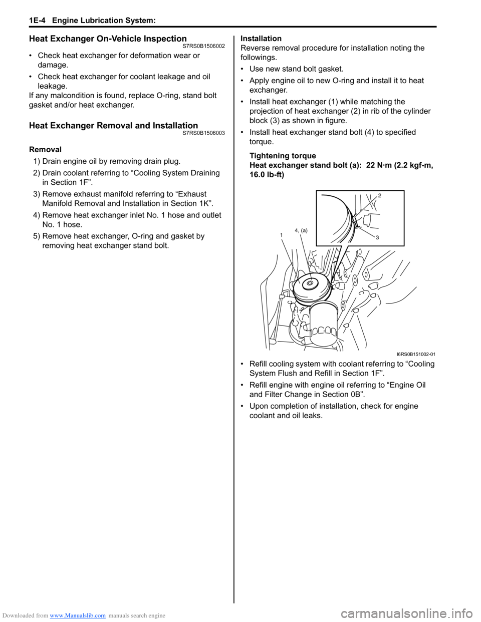
• Install heat exchanger (1) while matching the projection of heat exchanger (2) in rib of the cylinder
block (3) as shown in figure.
• Install heat exchanger stand bolt (4) to specified torque.
Tightening torque
Heat exchanger stand bolt (a): 22 N·m (2.2 kgf-m,
16.0 lb-ft)
• Refill cooling system with co olant referring to “Cooling
System Flush and Refill in Section 1F”.
• Refill engine with engine oil referring to “Engine Oil and Filter Change in Section 0B”.
• Upon completion of installation, check for engine coolant and oil leaks.
2
3
4, (a)
1
I6RS0B151002-01
Page 363 of 1496

Downloaded from www.Manualslib.com manuals search engine Engine Lubrication System: 1E-11
Specifications
Tightening Torque SpecificationsS7RS0B1507001
NOTE
The specified tightening torque is also described in the following.
“Heat Exchanger Components”
“Oil Pan and Oil Pump Strainer Components”
“Oil Pump Components”
Reference:
For the tightening torque of fastener not specified in this section, refer to “Fasteners Information in Section 0A”.
Special Tools and Equipment
Recommended Service MaterialS7RS0B1508001
NOTE
Required service material is also described in the following.
“Heat Exchanger Components”
“Oil Pan and Oil Pump Strainer Components”
“Oil Pump Components”
Special ToolS7RS0B1508002
Fastening part Tightening torque
Note
N ⋅mkgf-mlb-ft
Oil pressure switch 13 1.3 9.5 �)
Heat exchanger stand bolt 22 2.2 16.0 �)
Oil pump strainer bolt 11 1.1 8.0 �)
Oil pump strainer bracket bolt 11 1.1 8.0 �)
Oil pan bolt (M6) 11 1.1 8.0 �)
Oil pan bolt (M10) 55 5.5 40.0 �)
Oil pan nut 11 1.1 8.0 �)
Oil pan drain plug 35 3.5 25.5 �)
Transaxle stiffener bolt 55 5.5 40.0 �)
Oil pump rotor plate bolt 11 1.1 8.0 �)
MaterialSUZUKI recommended product or Specification Note
Sealant SUZUKI Bond No.1217G P/No.: 99000–31260�)
09915–77310 09915–78211
Oil pressure gauge (0-10kg/
cm2) Oil pressure gauge
attachment
�)�)
Page 365 of 1496

Downloaded from www.Manualslib.com manuals search engine Engine Cooling System: 1F-2
Coolant capacity
For M/T model:• Engine, radiator and heater: 5.5 liters (11.62/9.68 US/lmp pt.)
• Reservoir: 0.7 liters (1.48/1.23 US/lmp pt.)
• Total: 6.2 liters (13.10/10.91 US/lmp pt.)
For A/T model: • Engine, radiator and heater: 5.4 liters (11.41/9.50 US/lmp pt.)
• Reservoir: 0.7 liters (1.48/1.23 US/lmp pt.)
• Total: 6.1 liters (12.89/10.74 US/lmp pt.)
Schematic and Routing Diagram
Coolant CirculationS7RS0B1602001
While the engine is warmed up (thermosta t closed), coolant circulates as follows.
11
10 3 7
4
9
8
6
5
2 12 1
13
I6RS0C160001-01
1. Radiator inlet hose
6. Water pump11. Heater core
2. Radiator outlet hose 7. Throttle body12. Radiator
3. Throttle body inlet hose 8. Engine13. Heat exchanger
4. Throttle body outlet hose 9. Heater core inlet hose
5. Thermostat 10. Heater core outlet hose
Page 366 of 1496

Downloaded from www.Manualslib.com manuals search engine 1F-3 Engine Cooling System:
When coolant is warmed up to normal temperature and the thermostat opens, coolant passes through the radiator
core to be cooled as follows.
11
10 3 7
4
9
8
6
5
2 12 1
13
I6RS0C160002-01
1. Radiator inlet hose
6. Water pump11. Heater core
2. Radiator outlet hose 7. Throttle body12. Radiator
3. Throttle body inlet hose 8. Engine13. Heat exchanger
4. Throttle body outlet hose 9. Heater core inlet hose
5. Thermostat 10. Heater core outlet hose
Page 368 of 1496

Downloaded from www.Manualslib.com manuals search engine 1F-5 Engine Cooling System:
Repair Instructions
Cooling System ComponentsS7RS0B1606001
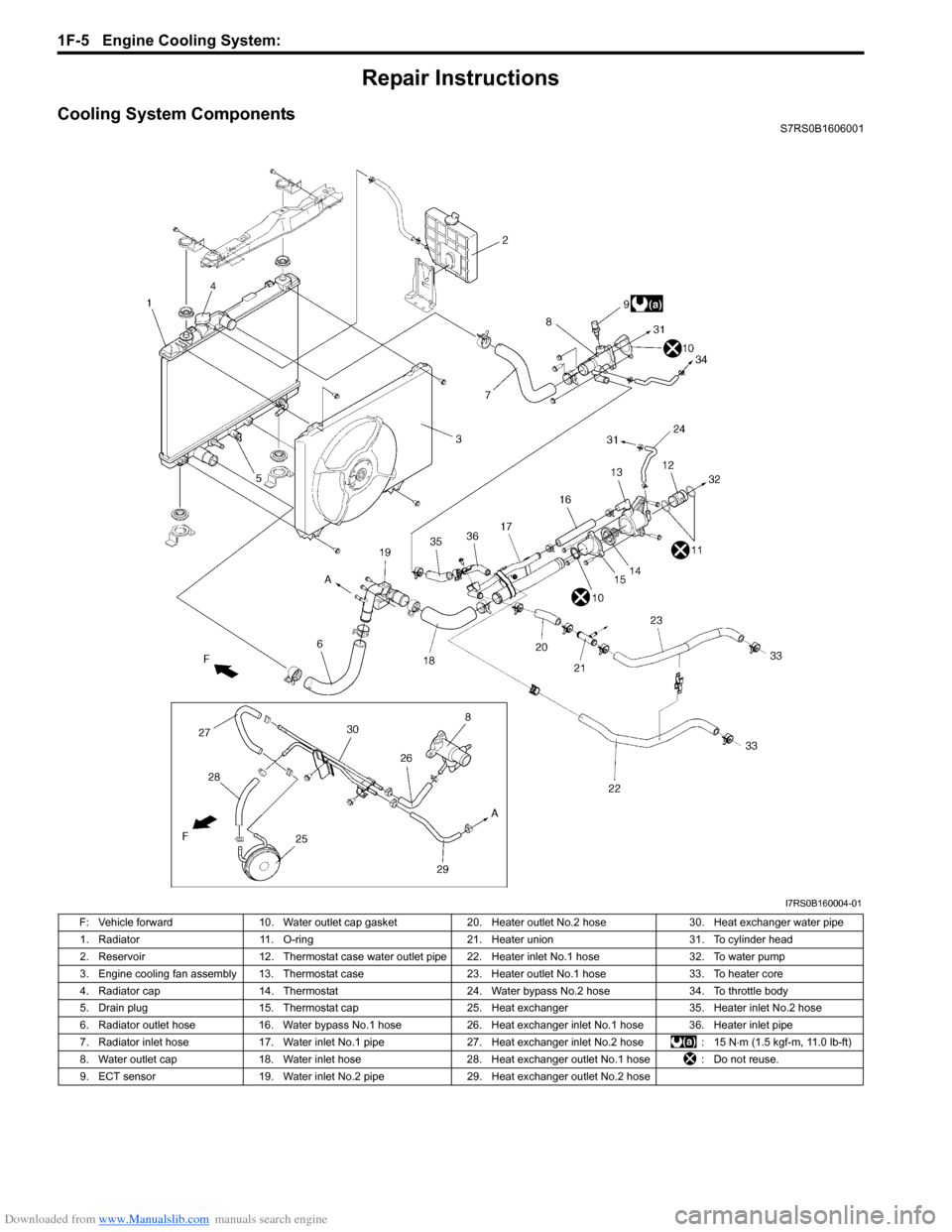
I7RS0B160004-01
F: Vehicle forward10. Water outlet cap gasket 20. Heater outlet No.2 hose 30. Heat exchanger water pipe
1. Radiator 11. O-ring 21. Heater union 31. To cylinder head
2. Reservoir 12. Thermostat case water outlet pipe 22. Heater inlet No.1 hose 32. To water pump
3. Engine cooling fan assembly 13. Thermostat case 23. Heater outlet No.1 hose33. To heater core
4. Radiator cap 14. Thermostat 24. Water bypass No.2 hose 34. To throttle body
5. Drain plug 15. Thermostat cap 25. Heat exchanger 35. Heater inlet No.2 hose
6. Radiator outlet hose 16. Water bypass No.1 hose 26.Heat exchanger inlet No.1 hose 36. Heater inlet pipe
7. Radiator inlet hose 17. Water inlet No.1 pipe 27. Heat exchanger inlet No.2 hose : 15 N⋅m (1.5 kgf-m, 11.0 lb-ft)
8. Water outlet cap 18. Water inlet hose 28. Heat exchanger outlet No.1 hose : Do not reuse.
9. ECT sensor 19. Water inlet No.2 pipe 29. Heat exchanger outlet No.2 hose