2005 SUZUKI SWIFT Crankshaft torque
[x] Cancel search: Crankshaft torquePage 47 of 1496

Downloaded from www.Manualslib.com manuals search engine Table of Contents 1-iii
EVAP Canister Purge Valve and Its Circuit
Inspection.......................................................... 1B-2
Vacuum Passage Inspection .............................. 1B-3
Vacuum Hose and Purge Valve Chamber Inspection.......................................................... 1B-3
EVAP Canister Purge Valve Inspection .............. 1B-3
EVAP Canister Inspection ... ................................ 1B-4
EGR Valve Removal and Installation .................. 1B-4
EGR Valve Inspection ......................................... 1B-4
PCV Hose Inspection .......................................... 1B-4
PCV Valve Inspection ......................................... 1B-5
Special Tools and Equipmen t ............................. 1B-5
Special Tool ........................................................ 1B-5
Engine Electrical Devices .. ..................... 1C-1
Repair Instructions .............................................. 1C-1
ECM Removal and Installation ............................ 1C-1
MAP Sensor Inspection ...................................... 1C-2
Electric Throttle Body Assembly On-Vehicle
Inspection.......................................................... 1C-2
Electric Throttle Body System Calibration ........... 1C-5
APP Sensor Assembly On-V ehicle Inspection .... 1C-5
APP Sensor Assembly Removal and Installation ......................................................... 1C-5
APP Sensor Assembly Inspection ...................... 1C-6
ECT Sensor Removal and In stallation ................ 1C-6
ECT Sensor Inspection ....................................... 1C-7
HO2S-1 and HO2S-2 Heater On-Vehicle Inspection.......................................................... 1C-7
HO2S-1 and HO2S-2 Removal and Installation ......................................................... 1C-7
CMP Sensor Removal and In stallation ............... 1C-8
Camshaft Position (CMP) Se nsor Inspection ...... 1C-8
CKP Sensor Removal and Installation ................ 1C-9
CKP Sensor Inspection ....................................... 1C-9
Knock Sensor Removal and Installation ........... 1C-10
Main Relay, Fuel Pump Relay and Starting
Motor Control Relay Inspection....................... 1C-10
MAF and IAT Sensor On-Vehicle Inspection .... 1C-11
MAF and IAT Sensor Removal and Installation ....................................................... 1C-11
MAF and IAT Sensor Inspection ....................... 1C-12
Electric Load Current Sensor On-Vehicle Inspection........................................................ 1C-12
Specifications ..................................................... 1C-13
Tightening Torque Specifications ...................... 1C-13
Engine Mechanical ......... ......................... 1D-1
General Description ............................................. 1D-1
Engine Construction Description ......................... 1D-1
Camshaft Position Control (VVT Variable Valve Timing) System Description .................... 1D-2
Diagnostic Information and Procedures ............ 1D-4 Compression Check ............................................ 1D-4
Engine Vacuum Check ....................................... 1D-5
Valve Lash (Clearance) Inspection ..................... 1D-6
Repair Instructions .............................................. 1D-9 Air Cleaner Components ..................................... 1D-9
Air Cleaner Element Removal and Installation .... 1D-9 Air Cleaner Element Ins
pection and Cleaning ..1D-10
Cylinder Head Co ver Removal and
Installation .......................................................1D-10
Throttle Body and Intake Manifold
Components ....................................................1D-12
Throttle Body On-Vehicle Inspection.................1D-13
Electric Throttle Body Assembly Removal and Installation .......................................................1D-13
Throttle Body Cleaning......................................1D-14
Intake Manifold Removal and Installation .........1D-14
Engine Mountings Components ........................1D-16
Engine Assembly Removal and Installation ......1D-17
Timing Chain Cover Components .....................1D-20
Timing Chain Cover Removal and Installation ..1D-21
Timing Chain Cover Inspection .........................1D-23
Oil Control Valve Removal and Installation .......1D-23
Oil Control Valve Inspection ..............................1D-24
Timing Chain and Chain Tensioner Components ....................................................1D-24
Timing Chain and Chain Tensioner Removal and Installation ................................................1D-25
Timing Chain and Chain Tensioner Inspection ..1D-27
Camshaft, Tappet and Shim Components ........1D-28
Camshaft, Tappet and Shim Removal and Installation .......................................................1D-29
Camshaft, Tappet and Shim Inspection ............1D-31
Valves and Cylinder Head Components ...........1D-34
Valves and Cylinder Head Removal and
Installation .......................................................1D-35
Valves and Cylinder Head Disassembly and Assembly.........................................................1D-37
Valves and Valve Guides Inspection.................1D-40
Cylinder Head Inspection . .................................1D-42
Valve Spring Inspection ....................................1D-43
Pistons, Piston Rings , Connecting Rods and
Cylinders Components ....................................1D-44
Pistons, Piston Rings , Connecting Rods and
Cylinders Removal and Installation .................1D-45
Pistons, Piston Rings , Connecting Rods and
Cylinders Disassembly and Assembly ............1D-46
Cylinders, Pistons and Piston Rings Inspection ........................................................1D-47
Piston Pins and Connecting Rods Inspection ...1D-49
Crank Pin and Connecting Rod Bearings Inspection ........................................................1D-50
Main Bearings, Cran kshaft and Cylinder
Block Components ..........................................1D-53
Main Bearings, Cran kshaft and Cylinder
Block Removal and Installa tion .......................1D-54
Crankshaft Inspection .......................................1D-57
Main Bearings Inspection . .................................1D-59
Sensor Plate Inspection ....................................1D-63
Rear Oil Seal Inspection ...................................1D-63
Flywheel Inspection...........................................1D-63
Cylinder Block Inspection ..................................1D-63
Specifications .................... .................................1D-64
Tightening Torque Specifications ......................1D-64
Special Tools and Equipmen t ...........................1D-66
Recommended Service Material .......................1D-66
Special Tool ......................................................1D-66
Page 293 of 1496

Downloaded from www.Manualslib.com manuals search engine Engine Mechanical: 1D-8
For example of intake side:
When thickness of removed shim is 2.40 mm (0.094
in.), and measured valve clearance is 0.45 mm
(0.018 in.).
A = 2.40 mm (0.094 in.) + 0.45 mm (0.018 in.) – 0.20
mm (0.008 in.) = 2.65 mm (0.104 in.)
Calculated thickness of new shim = 2.65 mm (0.104
in.)
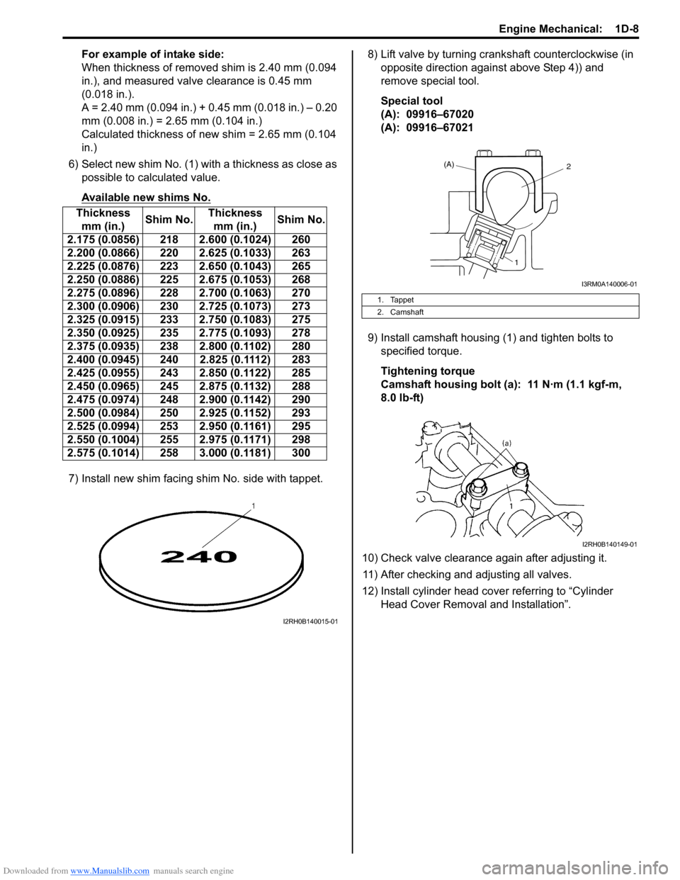
6) Select new shim No. (1) with a thickness as close as possible to calculated value.
Available new shims No.
7) Install new shim facing shim No. side with tappet. 8) Lift valve by turning crankshaft counterclockwise (in
opposite direction against above Step 4)) and
remove special tool.
Special tool
(A): 09916–67020
(A): 09916–67021
9) Install camshaft housing (1) and tighten bolts to specified torque.
Tightening torque
Camshaft housing bolt (a ): 11 N·m (1.1 kgf-m,
8.0 lb-ft)
10) Check valve clearance again after adjusting it. 11) After checking and adjusting all valves.
12) Install cylinder head cover referring to “Cylinder Head Cover Removal and Installation”.
Thickness
mm (in.) Shim No.Thickness
mm (in.) Shim No.
2.175 (0.0856) 218 2.600 (0.1024) 260
2.200 (0.0866) 220 2.625 (0.1033) 263
2.225 (0.0876) 223 2.650 (0.1043) 265
2.250 (0.0886) 225 2.675 (0.1053) 268
2.275 (0.0896) 228 2.700 (0.1063) 270
2.300 (0.0906) 230 2.725 (0.1073) 273
2.325 (0.0915) 233 2.750 (0.1083) 275
2.350 (0.0925) 235 2.775 (0.1093) 278
2.375 (0.0935) 238 2.800 (0.1102) 280
2.400 (0.0945) 240 2.825 (0.1112) 283
2.425 (0.0955) 243 2.850 (0.1122) 285
2.450 (0.0965) 245 2.875 (0.1132) 288
2.475 (0.0974) 248 2.900 (0.1142) 290
2.500 (0.0984) 250 2.925 (0.1152) 293
2.525 (0.0994) 253 2.950 (0.1161) 295
2.550 (0.1004) 255 2.975 (0.1171) 298
2.575 (0.1014) 258 3.000 (0.1181) 300
I2RH0B140015-01
1. Tappet
2. Camshaft
(A)2
1
I3RM0A140006-01
I2RH0B140149-01
Page 308 of 1496

Downloaded from www.Manualslib.com manuals search engine 1D-23 Engine Mechanical:
8) Install new O-ring (1) to oil gallery pipes No.2 (2) and
No.3 (3).
9) Install oil gallery pipes No.2 and No.3 to cylinder
head (4) and timing chain cover (5).
Tighten bolts to specified torque.
Tightening torque
Oil gallery pipe No.2 and No.3 bolt (a): 11 N·m (
1.1 kgf-m, 8.0 lb-ft)
10) Install water pump pulley. 11) Install cylinder head cover referring to “Cylinder Head Cover Removal and Installation”.
12) Install oil pan referring to “Oil Pan and Oil Pump
Strainer Removal and Installation in Section 1E”.
13) Install crankshaft pulley (1). Tighten bolt (2) to specified torque. To lock crankshaft pulley, use
special tool with it as shown in figure.
Special tool
(A): 09917–68221
Tightening torque
Crankshaft pulley bolt (a): 150 N·m (15.0 kgf-m,
108.5 lb-ft)
14) Install engine assembly to vehicle referring to “Engine Assembly Removal and Installation”.
Timing Chain Cover InspectionS7RS0B1406014
Oil Seal
Check oil seal lip for fault or other damage. Replace as
necessary. Timing Chain Cover
Inspect strainer (1) of oil passage for driving intake cam
timing sprocket assembly (VVT actuator).
If clog or foreign matter exists, clean strainer.
Oil Control Valve Removal and InstallationS7RS0B1406015
Removal
Remove oil gallery pipe No.1
(1) and oil control valve (2)
from timing chain cover (3).
Installation
1) Install new O-ring (4) to oil control valve.
2) Install oil control valve to timing chain cover. Tighten nuts to specification.
Tightening torque
Oil control valve mounting nut (a): 11 N·m (1.1
kgf-m, 8.0 lb-ft)
3) Install oil gallery pipe No .1 with new copper washers
(5) to timing chain cover.
Tighten bolts to specification.
Tightening torque
Oil gallery pipe No.1 bolt (b): 30 N·m (3.0 kgf-m,
21.5 lb-ft)
(a)
(a) 1
2
3
4
5
I3RH0B140027-01
I2RH0B140056-01
1
I3RH0B140028-01
1
5
(b) 3
(a)
2 4
5
I3RM0A140027-01
Page 311 of 1496

Downloaded from www.Manualslib.com manuals search engine Engine Mechanical: 1D-26
3) Install timing chain by aligning dark blue plate (1) of timing chain and triangle mark (2) on camshaft
timing sprocket as shown in figure.
4) Fit crankshaft timing sprocket to timing chain by aligning gold plate (3) of timing chain and circle mark
(4) on crankshaft timing sprocket. Then install
crankshaft timing sprocket fitted with chain to
crankshaft.
5) Apply engine oil to sliding surface of timing chain No.1 guide (1) and install it as shown in figure.
Tighten guide bolts to specified torque.
Tightening torque
Timing chain No.1 guide bolt (a): 9 N·m (0.9 kgf-
m, 6.5 lb-ft) 6) Apply engine oil to sliding surface of chain tensioner
(1) and install chain tensioner and spacer.
Tighten tensioner bolt to specified torque.
Tightening torque
Timing chain tensioner bolt (a): 25 N·m (2.5 kgf-
m, 18.0 lb-ft)
7) Check that match marks (2) on intake and exhaust camshaft timing sprockets are in match with dark
blue plates (1) of timing chain and match mark (4) on
crankshaft timing sprocket is in match with gold plate
(3) of timing chain.
[A]: View C
34
1
1
2
2
Approx. Approx.
C[A]
I6RS0C140016-02
I2RH0B140062-01
[A]: View C
I2RH0B140063-01
34
1
1
2
2
Approx. Approx.
C[A]
I6RS0C140016-02
Page 312 of 1496

Downloaded from www.Manualslib.com manuals search engine 1D-27 Engine Mechanical:
8) Screw in plunger (1) by turning body (2) in arrow direction and install a reta iner (3) (wire) to hold
plunger in place.
9) Install timing chain tensioner adjuster assembly (1) with a retainer (2).
Tighten adjuster bolts to specified torque and then
remove a retainer from chain tensioner adjuster
assembly.
Tightening torque
Timing chain tensioner adjuster bolt (a): 11 N·m
(1.1 kgf-m, 8.0 lb-ft)
10) Apply engine oil to timing chain, and then turn crankshaft clockwise by 2 revolutions and check that
match marks (1) are at the following specific
positions.
• Intake and exhaust camshaft timing sprockets makes (1) are in match with notches (2) on
cylinder head.
• Crankshaft sprocket key (3) is in match with notch of cylinder block (4).
• Crankshaft sprocket key (3) is on upside of crankshaft as shown in figure. 11) Install timing chain cover referring to “Timing Chain
Cover Removal and Installation”.
Timing Chain and Chain Tensioner InspectionS7RS0B1406019
Timing Chain No.1 Guide
Check shoe (1) for wear or damage.
Timing Chain Tensioner
Check shoe (1) for wear or damage.
I2RH0B140065-01
I2RH0B140066-01
1
1
2
3 4
I6RS0C140017-01
I2RH0B140068-01
I2RH0B140069-01
Page 320 of 1496

Downloaded from www.Manualslib.com manuals search engine 1D-35 Engine Mechanical:
Valves and Cylinder Head Removal and
Installation
S7RS0B1406024
Removal1) Remove engine assembly from vehicle referring to “Engine Assembly Removal and Installation”.
2) Remove oil pan referring to “Oil Pan and Oil Pump
Strainer Removal and Installation in Section 1E”.
3) Remove cylinder head cover referring to “Cylinder Head Cover Removal and Installation”.
4) Remove timing chain cover referring to Steps 2) to 11) of “Removal” in “Tim ing Chain Cover Removal
and Installation”.
5) Remove timing chain referring to Steps 2) to 6) of “Removal” in “Timing Chain and Chain Tensioner
Removal and Installation”.
6) Remove intake and exhaust camshafts referring to Steps 3) to 8) of “Removal” in “Camshaft, Tappet and
Shim Removal and Installation”.
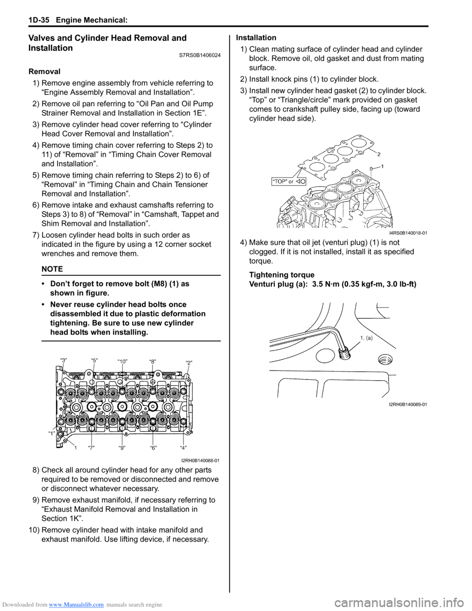
7) Loosen cylinder head bolts in such order as indicated in the figure by using a 12 corner socket
wrenches and remove them.
NOTE
• Don’t forget to remove bolt (M8) (1) as shown in figure.
• Never reuse cylinder head bolts once disassembled it due to plastic deformation
tightening. Be sure to use new cylinder
head bolts when installing.
8) Check all around cylinder head for any other parts required to be removed or disconnected and remove
or disconnect whatever necessary.
9) Remove exhaust manifold, if necessary referring to
“Exhaust Manifold Removal and Installation in
Section 1K”.
10) Remove cylinder head wi th intake manifold and
exhaust manifold. Use lifting device, if necessary. Installation
1) Clean mating surface of cylinder head and cylinder block. Remove oil, old gasket and dust from mating
surface.
2) Install knock pins (1) to cylinder block.
3) Install new cylinder head gasket (2) to cylinder block. “Top” or “Triangle/circle” mark provided on gasket
comes to crankshaft pulley side, facing up (toward
cylinder head side).
4) Make sure that oil jet (venturi plug) (1) is not clogged. If it is not install ed, install it as specified
torque.
Tightening torque
Venturi plug (a): 3.5 N·m (0.35 kgf-m, 3.0 lb-ft)
I2RH0B140088-01
I4RS0B140018-01
I2RH0B140089-01
Page 330 of 1496

Downloaded from www.Manualslib.com manuals search engine 1D-45 Engine Mechanical:
Pistons, Piston Rings, Connecting Rods and
Cylinders Removal and Installation
S7RS0B1406030
Removal1) Remove engine assembly from vehicle referring to “Engine Assembly Removal and Installation”.
2) Remove cylinder head referring to “Valves and Cylinder Head Removal and Installation”.
3) Mark cylinder number on all pistons, connecting rods
and connecting rod caps using silver pencil or quick
drying paint.
4) Remove rod bearing caps.
5) Decarbonize top of cylinder bore before removing piston from cylinder.
6) Push piston and connecting rod assembly out through the top of cylinder bore.
Installation 1) Apply engine oil to pistons, rings, cylinder walls, connecting rod bearings and crank pins.
NOTE
Do not apply oil between connecting rod and
bearing or between bearing cap and bearing.
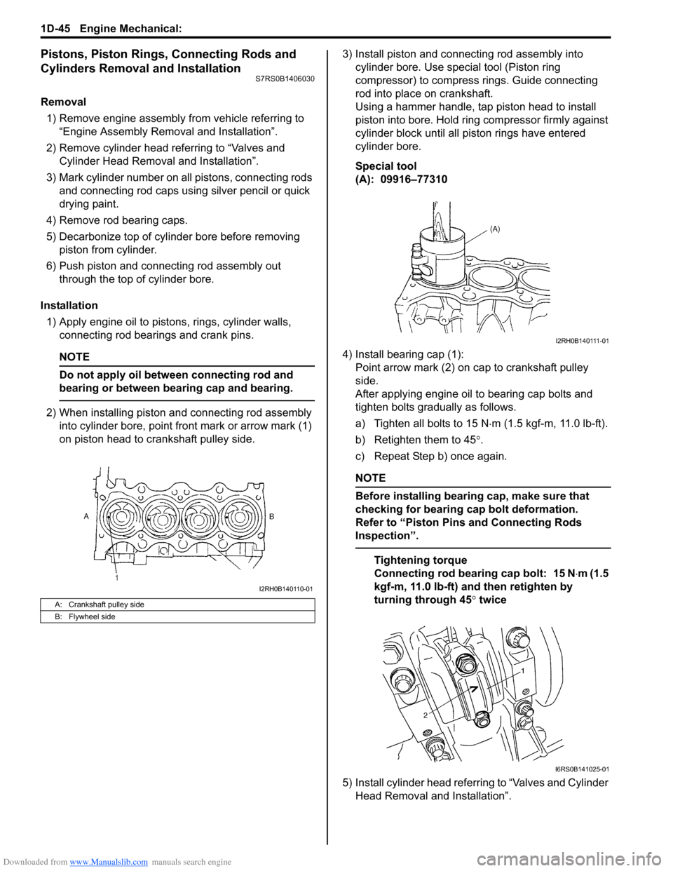
2) When installing piston and connecting rod assembly into cylinder bore, point front mark or arrow mark (1)
on piston head to crankshaft pulley side. 3) Install piston and connecting rod assembly into
cylinder bore. Use special tool (Piston ring
compressor) to compress rings. Guide connecting
rod into place on crankshaft.
Using a hammer handle, tap piston head to install
piston into bore. Hold ring compressor firmly against
cylinder block until all piston rings have entered
cylinder bore.
Special tool
(A): 09916–77310
4) Install bearing cap (1): Point arrow mark (2) on cap to crankshaft pulley
side.
After applying engine oil to bearing cap bolts and
tighten bolts gradually as follows.
a) Tighten all bolts to 15 N ⋅m (1.5 kgf-m, 11.0 lb-ft).
b) Retighten them to 45 °.
c) Repeat Step b) once again.
NOTE
Before installing bearing cap, make sure that
checking for bearing cap bolt deformation.
Refer to “Piston Pins and Connecting Rods
Inspection”.
Tightening torque
Connecting rod bearing cap bolt: 15 N ⋅m (1.5
kgf-m, 11.0 lb-ft) and then retighten by
turning through 45 ° twice
5) Install cylinder head referring to “Valves and Cylinder Head Removal and Installation”.
A: Crankshaft pulley side
B: Flywheel side
I2RH0B140110-01
I2RH0B140111-01
I6RS0B141025-01
Page 336 of 1496

Downloaded from www.Manualslib.com manuals search engine 1D-51 Engine Mechanical:
Connecting Rod Bearing Clearance1) Before checking bearing clearance, clean bearing and crank pin.
2) Install bearing in connecting rod and bearing cap.
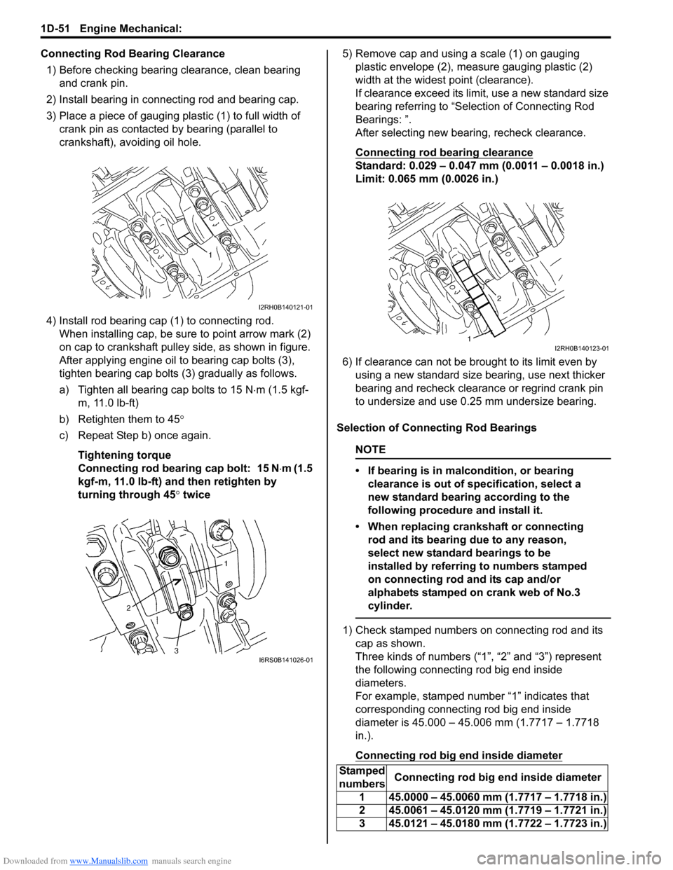
3) Place a piece of gauging plastic (1) to full width of crank pin as contacted by bearing (parallel to
crankshaft), avoiding oil hole.
4) Install rod bearing cap (1) to connecting rod. When installing cap, be sure to point arrow mark (2)
on cap to crankshaft pulley side, as shown in figure.
After applying engine oil to bearing cap bolts (3),
tighten bearing cap bolts (3) gradually as follows.
a) Tighten all bearing cap bolts to 15 N ⋅m (1.5 kgf-
m, 11.0 lb-ft)
b) Retighten them to 45°
c) Repeat Step b) once again.
Tightening torque
Connecting rod bearing cap bolt: 15 N ⋅m (1.5
kgf-m, 11.0 lb-ft) and then retighten by
turning through 45 ° twice 5) Remove cap and using a scale (1) on gauging
plastic envelope (2), measure gauging plastic (2)
width at the widest point (clearance).
If clearance exceed its limit, use a new standard size
bearing referring to “Selection of Connecting Rod
Bearings: ”.
After selecting new bearing, recheck clearance.
Connecting rod bearing clearance
Standard: 0.029 – 0.047 mm (0.0011 – 0.0018 in.)
Limit: 0.065 mm (0.0026 in.)
6) If clearance can not be brought to its limit even by using a new standard size bearing, use next thicker
bearing and recheck clearance or regrind crank pin
to undersize and use 0.25 mm undersize bearing.
Selection of Connecting Rod Bearings
NOTE
• If bearing is in malcondition, or bearing clearance is out of specification, select a
new standard bearing according to the
following procedure and install it.
• When replacing crankshaft or connecting rod and its bearing due to any reason,
select new standard bearings to be
installed by referring to numbers stamped
on connecting rod and its cap and/or
alphabets stamped on crank web of No.3
cylinder.
1) Check stamped numbers on connecting rod and its cap as shown.
Three kinds of numbers (“1”, “2” and “3”) represent
the following connecting rod big end inside
diameters.
For example, stamped number “1” indicates that
corresponding connecting rod big end inside
diameter is 45.000 – 45.006 mm (1.7717 – 1.7718
in.).
Connecting rod big end inside diameter
I2RH0B140121-01
I6RS0B141026-01
Stamped
numbers Connecting rod big end inside diameter
1 45.0000 – 45.0060 mm (1.7717 – 1.7718 in.)
2 45.0061 – 45.0120 mm (1.7719 – 1.7721 in.)
3 45.0121 – 45.0180 mm (1.7722 – 1.7723 in.)
I2RH0B140123-01