Page 418 of 1496

Downloaded from www.Manualslib.com manuals search engine 1J-8 Charging System:
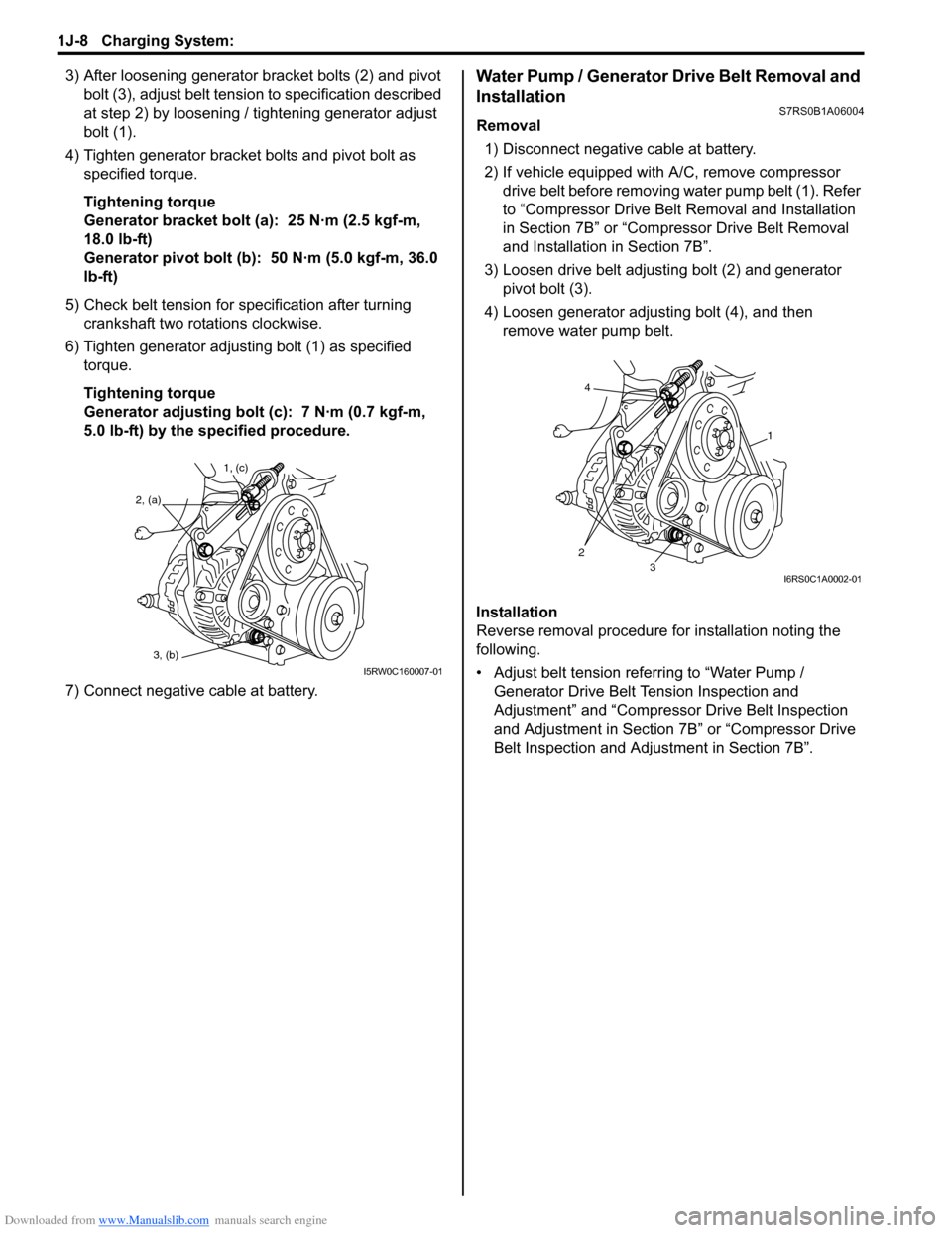
3) After loosening generator bracket bolts (2) and pivot bolt (3), adjust belt tensio n to specification described
at step 2) by loosening / tightening generator adjust
bolt (1).
4) Tighten generator bracket bolts and pivot bolt as specified torque.
Tightening torque
Generator bracket bolt (a): 25 N·m (2.5 kgf-m,
18.0 lb-ft)
Generator pivot bolt (b): 50 N·m (5.0 kgf-m, 36.0
lb-ft)
5) Check belt tension for specification after turning crankshaft two rotations clockwise.
6) Tighten generator adjusting bolt (1) as specified torque.
Tightening torque
Generator adjusting bolt (c): 7 N·m (0.7 kgf-m,
5.0 lb-ft) by the specified procedure.
7) Connect negative cable at battery.Water Pump / Generator Drive Belt Removal and
Installation
S7RS0B1A06004
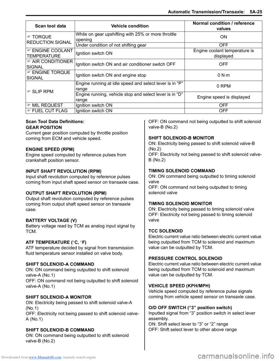
Removal 1) Disconnect negative cable at battery.
2) If vehicle equipped with A/C, remove compressor drive belt before removing water pump belt (1). Refer
to “Compressor Drive Belt Removal and Installation
in Section 7B” or “Compr essor Drive Belt Removal
and Installation in Section 7B”.
3) Loosen drive belt adjusting bolt (2) and generator pivot bolt (3).
4) Loosen generator adjusting bolt (4), and then remove water pump belt.
Installation
Reverse removal procedure for installation noting the
following.
• Adjust belt tension referring to “Water Pump / Generator Drive Belt Tension Inspection and
Adjustment” and “Compressor Drive Belt Inspection
and Adjustment in Section 7B” or “Compressor Drive
Belt Inspection and Adjustment in Section 7B”.
1, (c)
2, (a)
3, (b)
I5RW0C160007-01
4
23
1
I6RS0C1A0002-01
Page 669 of 1496

Downloaded from www.Manualslib.com manuals search engine Automatic Transmission/Transaxle: 5A-25
Scan Tool Data Definitions:
GEAR POSITION
Current gear position computed by throttle position
coming from ECM and vehicle speed.
ENGINE SPEED (RPM)
Engine speed computed by reference pulses from
crankshaft position sensor.
INPUT SHAFT REVOLUTION (RPM)
Input shaft revolution computed by reference pulses
coming from input shaft speed sensor on transaxle case.
OUTPUT SHAFT REVOLUTION (RPM)
Output shaft revolution computed by reference pulses
coming from output shaft speed sensor on transaxle
case.
BATTERY VOLTAGE (V)
Battery voltage read by TCM as analog input signal by
TCM.
ATF TEMPERATURE (°C, °F)
ATF temperature decided by signal from transmission
fluid temperature sensor installed on valve body.
SHIFT SOLENOID-A COMMAND
ON: ON command being outputted to shift solenoid
valve-A (No.1)
OFF: ON command not being outputted to shift solenoid
valve-A (No.1)
SHIFT SOLENOID-A MONITOR
ON: Electricity being passed to shift solenoid valve-A
(No.1)
OFF: Electricity not being passed to shift solenoid valve-
A (No.1)
SHIFT SOLENOID-B COMMAND
ON: ON command being outputted to shift solenoid
valve-B (No.2) OFF: ON command not being outputted to shift solenoid
valve-B (No.2)
SHIFT SOLENOID-B MONITOR
ON: Electricity being passed to shift solenoid valve-B
(No.2)
OFF: Electricity not being passed to shift solenoid valve-
B (No.2)
TIMING SOLENOID COMMAND
ON: ON command being outputted to timing solenoid
valve
OFF: ON command not being outputted to timing
solenoid valve
TIMING SOLENOID MONITOR
ON: Electricity being passed to timing solenoid valve
OFF: Electricity not being passed to timing solenoid
valve
TCC SOLENOID
Electric current value ratio between electric current value
being outputted from TCM to solenoid and maximum
value can be outputted by TCM.
PRESSURE CONTROL SOLENOID
Electric current value ratio between electric current value
being outputted from TCM to solenoid and maximum
value can be outputted by TCM.
VEHICLE SPEED (KPH/MPH)
Vehicle speed computed by reference pulse signals
coming from vehicle speed sensor on transaxle case.
O/D OFF SWITCH (“3” position switch)
Inputted signal from “3” position switch in select lever
assembly.
ON: Shift select lever to “3” or “2” range
OFF: Shift select lever to other above range
�)
TORQUE
REDUCTION SIGNAL While on gear upshifting with 25% or more throttle
opening
ON
Under condition of not shifting gear OFF
�) ENGINE COOLANT
TEMPERATURE Ignition switch ON Engine coolant temperature is
displayed
�) AIR CONDITIONER
SIGNAL Ignition switch ON and air conditioner switch OFF OFF
�) ENGINE TORQUE
SIGNAL Ignition switch ON and engine stop 0 N
⋅m
�) SLIP RPM Engine running at idle speed
and select lever is in “P”
range 0 RPM
Engine running, vehicle stop and select lever is in “D”
range Engine speed is displayed
�) MIL REQUEST Ignition switch ON OFF
�) FUEL CUT FLAG Ignition switch ON OFFScan tool data Vehicle condition
Normal condition / reference
values
Page 861 of 1496
Downloaded from www.Manualslib.com manuals search engine Clutch: 5C-9
3) Pull out input shaft bearing (1) from flywheel (2), use the following special tool if necessary.
Special tool
(A): 09921–26020
(B): 09930–30104
4) Remove flywheel (1) from crank shaft using special tool.
Special tool
(A): 09924–17811 Installation
CAUTION!
Do not reuse flywheel bolts. Otherwise, bolts
may loosen. Be sure to use new bolts with
pre-coated adhesive.
NOTE
Before assembling, make
sure that flywheel
surface and pressure plate surface have
been cleaned and dried thoroughly.
1) Install flywheel (2) to crankshaft and tighten new bolts (1) to specification.
Special tool
(A): 09924–17811
Tightening torque
Flywheel bolt (a): 70 N·m (7.0 kgf-m, 51.0 lb-ft)
2) Using special tool, install input shaft bearing to flywheel (1).
Special tool
(B): 09925–98210
I2RH01530023-01
I4RS0A530015-02
I2RH01530024-01
I4RS0A530016-01
Page 862 of 1496

Downloaded from www.Manualslib.com manuals search engine 5C-10 Clutch:
3) Aligning clutch disc to flywheel center using special
tool, install clutch cover (1) and bolts (2). Then
tighten bolts (2) to specification.
NOTE
• While tightening clutch cover bolts, compress clutch disc with special tool
(clutch center guide) by hand so that disc
is centered.
• Tighten cover bolts little by little evenly in diagonal order.
Special tool
(A): 09924–17811
(B): 09923–36320
Tightening torque
Clutch cover bolt (a): 23 N·m (2.3 kgf-m, 17.0 lb-
ft)
4) Slightly apply grease to input shaft (1), then join manual transaxle assembly with engine referring to
“Manual Transaxle Unit Dismounting and
Remounting in Section 5B”.
“A”: Grease 99000–25210 (SUZUKI Super
Grease I)
NOTE
When inserting transaxle input shaft to clutch
disc, turn crankshaft li ttle by little to match
the splines.
Clutch Cover, Clutch Disc and Flywheel
Inspection
S7RS0B5306015
Input Shaft Bearing
Check bearing (1) for smooth ro tation and replace it if
abnormality is found.
Clutch Disc
Measure depth of rivet head depression, i.e. distance
between rivet head and facing surface.
If depression is found to hav e reached service limit at
any of rivet holes (2), repl ace clutch disc assembly (1).
Rivet head depth
Standard: 1.65 – 2.25 mm (0.06 – 0.09 in.)
Limit: 0.5 mm (0.02 in.)
I4RS0A530017-01
I4RS0A530018-01
I3RM0A530014-01
I4RS0A530019-01
Page:
< prev 1-8 9-16 17-24