2005 SUZUKI SWIFT Oxygen sensor relay
[x] Cancel search: Oxygen sensor relayPage 55 of 1496

Downloaded from www.Manualslib.com manuals search engine Engine General Information and Diagnosis: 1A-5
Freeze frame data clearance:
The freeze frame data is cleared at the same time as
clearance of DTC.
Non-Euro-OBD
ECM diagnosis troubles which may occur in the area
including the following parts w hen the ignition switch is
ON and the engine is running, and indicates the result by
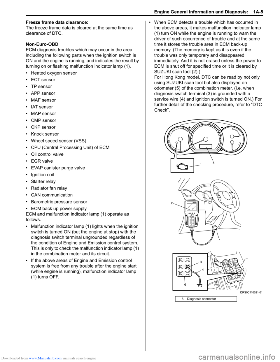
turning on or flashing malfunction indicator lamp (1).
• Heated oxygen sensor
• ECT sensor
•TP sensor
• APP sensor
• MAF sensor
• IAT sensor
• MAP sensor
• CMP sensor
• CKP sensor
• Knock sensor
• Wheel speed sensor (VSS)
• CPU (Central Processing Unit) of ECM
• Oil control valve
• EGR valve
• EVAP canister purge valve
• Ignition coil
• Starter relay
• Radiator fan relay
• CAN communication
• Barometric pressure sensor
• ECM back up power supply
ECM and malfunction indicator lamp (1) operate as
follows.
• Malfunction indicator lamp (1) lights when the ignition switch is turned ON (but t he engine at stop) with the
diagnosis switch terminal ungrounded regardless of
the condition of Engine and Emission control system.
This is only to check the ma lfunction indicator lamp (1)
in the combination meter and its circuit.
• If the above areas of Engine and Emission control system is free from any trouble after the engine start
(while engine is running), malfunction indicator lamp
(1) turns OFF. • When ECM detects a trouble which has occurred in
the above areas, it makes malfunction indicator lamp
(1) turn ON while the engi ne is running to warn the
driver of such occurrence of trouble and at the same
time it stores the trouble area in ECM back-up
memory. (The memory is kept as it is even if the
trouble was only temporary and disappeared
immediately. And it is not erased unless the power to
ECM is shut off for specified time or it is cleared by
SUZUKI scan tool (2).)
For Hong Kong model, DTC can be read by not only
using SUZUKI scan tool but also displayed on
odometer (5) of the combination meter. (i.e. when
diagnosis switch terminal (3) is grounded with a
service wire (4) and ignition switch is turned ON.) For
further detail of the checking procedure, refer to “DTC
Check”.
6. Diagnosis connector
2
1
6 3
5
4
I5RS0C110021-01
Page 86 of 1496

Downloaded from www.Manualslib.com manuals search engine 1A-36 Engine General Information and Diagnosis:
O2S B1 S1 ACT (HEATED OXYGEN SENSOR-1,
ACTIVE / INACTIVE)
This parameter indicates activation condition of HO2S-1.
ACTIVE: Activating
INACTIVE: warming up or at stop
O2S SENSOR B1 S2 (HEATED OXYGEN SENSOR-2,
V)
It indicates output voltage of HO2S-2 installed on
exhaust pipe (post-catalyst). It is used to detect catalyst
deterioration.
O2S B1 S2 ACT (HEATED OXYGEN SENSOR-2,
ACTIVE / INACTIVE)
This parameter indicates acti vation condition of HO2S-2.
ACTIVE: Activating
INACTIVE: warming up or at stop
FUEL SYSTEM (FUEL SYSTEM STATUS)
Air/fuel ratio feedback loop status displayed as one of
the followings.
OPEN: Open-loop has not yet satisfied conditions to go
closed loop.
CLOSED: Closed-loop using oxygen sensor(s) as
feedback for fuel control.
OPEN-DRIVE COND: Open-loop due to driving
conditions (Power enrichment, etc.).
OPEN SYS FAULT: Open-loop due to detected system
fault.
MAP (MANIFOLD ABSOLUTE PRESSURE, in.Hg,
kPa)
This value indicates how much correction is necessary
to keep the air/fuel mixture stoichiometrical.
It is detected by manifold absolute pressure sensor.
BAROMETRIC PRESS (kPa, in.Hg)
This parameter represents a measurement of barometric
air pressure and is used for al titude correction of the fuel
injection quantity and IAC valve control.
STEP EGR FLOW DUTY (%)
This parameter indicates opening rate of EGR valve
which controls the amount of EGR flow.
FUEL CUT (ON/OFF)
ON: Fuel being cut (output signal to injector is stopped)
OFF: Fuel not being cut
A/C PRESSURE (A/C REFRIGERANT ABSOLUTE
PRESSURE, kPa)
This parameter indicates A/C refrigerant absolute
pressure calculated by ECM.
CLOSED THROTTLE PO S (CLOSED THROTTLE
POSITION, ON/OFF)
This parameter reads ON wh en throttle valve is fully
closed, or OFF when it is not fully closed. CANIST PRG DUTY (EVAP CANISTER PURGE FLOW
DUTY, %)
This parameter indicates valve ON (valve open) time
rate within a certain set cycle of EVAP canister purge
valve which controls the amount of EVAP purge.
IGNITION ADVANCE (IGNITION TIMING ADVANCE
FOR NO.1 CYLINDER,
°)
Ignition timing of No.1 cylinder is commanded by ECM.
The actual ignition timing should be checked by using
the timing light.
BATTERY VOLTAGE (V)
This parameter indicates battery positive voltage
inputted from main relay to ECM.
FUEL PUMP (ON/OFF)
ON is displayed when ECM activates the fuel pump via
the fuel pump relay switch.
ELECTRIC LOAD (ON/OFF)
ON: Headlight or small light ON signal inputted.
OFF: Above electric loads all turned OFF.
BRAKE SW (ON/OFF)
This parameter indicates the state of the brake switch.
RADIATOR COOLING FAN (RADIATOR COOLING
FAN CONTROL RELAY, ON/OFF)
ON: Command for radiator cooling fan control relay
operation being output.
OFF: Command for relay operation not being output.
BLOWER FAN (ON/OFF)
This parameter indicates the state of the blower fan
motor switch.
A/C SWITCH (ON/OFF)
ON: Command for A/C operatio n being output from ECM
to HVAC.
OFF: Command for A/C oper ation not being output.
A/C COMP RELAY (A/C COMPRESSOR RELAY, ON/
OFF)
This parameter indicates the state of the A/C switch.
VEHICLE SPEED (km/h, mph)
It is computed based on pulse signals from vehicle
speed sensor.
VVT GAP (TARGET-ACTUAL POSITION, °)
It is calculated using the formula: target valve timing
advance – actual valve timing advance.
TP SENSOR 1 VOLT (THROTTLE POSITION SENSOR
(MAIN) OUTPUT VOLTAGE, V)
The TP sensor (main) reading provides throttle valve
opening information in the form of voltage.
Page 1206 of 1496

Downloaded from www.Manualslib.com manuals search engine 9A-35 Wiring Systems:
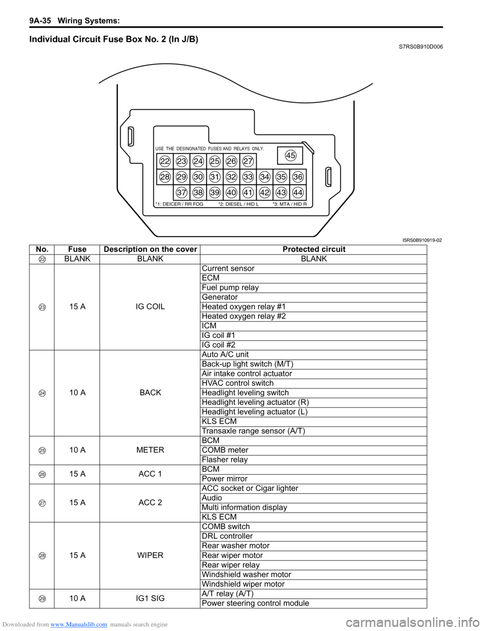
Individual Circuit Fuse Box No. 2 (In J/B)S7RS0B910D006
22
28
23
29
37
24
30
38
25
31
39
26
32
40
27
33
41
34
42
35
43
36
44
45USE THE DESINGNATED FUSES AND RELAYS ONLY.
*1: DEICER / RR FOG *2: DIESEL / HID L *3: MTA / HID R
I5RS0B910919-02
No. Fuse Description on the coverProtected circuit
BLANK BLANK BLANK
15 A IG COILCurrent sensor
ECM
Fuel pump relay
Generator
Heated oxygen relay #1
Heated oxygen relay #2
ICM
IG coil #1
IG coil #2
10 A BACKAuto A/C unit
Back-up light switch (M/T)
Air intake control actuator
HVAC control switch
Headlight leveling switch
Headlight leveling actuator (R)
Headlight leveling actuator (L)
KLS ECM
Transaxle range sensor (A/T)
10 A METERBCM
COMB meter
Flasher relay
15 A ACC 1BCM
Power mirror
15 A ACC 2ACC socket or Cigar lighter
Audio
Multi information display
KLS ECM
15 A WIPERCOMB switch
DRL controller
Rear washer motor
Rear wiper motor
Rear wiper relay
Windshield washer motor
Windshield wiper motor
10 A IG1 SIGA/T relay (A/T)
Power steering control module
Page 1221 of 1496

Downloaded from www.Manualslib.com manuals search engine Wiring Systems: 9A-50
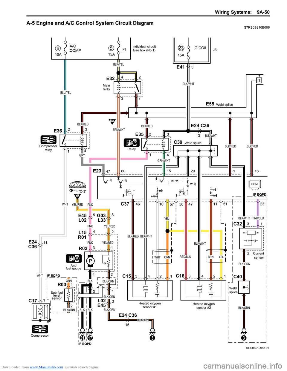
A-5 Engine and A/C Control System Circuit DiagramS7RS0B910E006
YEL/RED
E45L02 G03
L33
L02
E4558
L15
R0142
PNKYEL/RED
P
PNKYEL/RED
31
3
3 1
E24 C36
BLK/ORN
BLK/ORN
BLK/ORN
BLK/ORN
3
15
BLK
42
R02
1
2
R03
And
fuel gauge
Sub fuel level
sensor
Main
relay
1BLK/WHT
BLK/WHT
C39Weld splice Weld splice
E55
GRN/WHT
IG COILJ/B5
15A
FI
BLK/YEL
E324
32
1 15A
23
BRN/WHT
BW
YR
6
10A
A/C
COMP
Compressor
relay
E36
Relay
BLU/YEL
Compressor
C171
E415
E24 C36
3
E24
C3611
BLK/WHT
C15 C16
Heated oxygen
sensor #1
BLK/RED
WHT
Heated oxygensensor #2
BRN
BLK/WHT
RED/BLU
C37
34213421
4610574711
YEL
5123PNK
ECM
41 3
2
WHT
WHT
BLK/REDBLK/RED
BLK/RED
E23476015291
GRY
E3523
1
4
ORN
BLKBLKBLK/ORN
ORN
YEL
50
BLK/RED
16
17213
Individual circuit
fuse box (No.1)
BLK/ORN
BLK/ORN
BLK/WHTPNK/BLU
IF EQPD
IF EQPD IF EQPD
Weld
splice
C40 C32
Current
sensor
3
2 1
"C-3"
I7RS0B910912-01