Page 798 of 1496

Downloaded from www.Manualslib.com manuals search engine 5A-154 Automatic Transmission/Transaxle:
20) Check for correct installation of planetary gear assembly as follows.
Measure the distance “a” by using micrometer
caliper (1) and straightedge (2). If measured value is
out of specification, remove planetary gear assembly
and reinstall it properly.
Distance between planetary gear assembly and
mating surface of transaxle case
“a”: More than 49.9 m (1.965 in.)
21) Apply A/T fluid to one-way clutch No.2 assembly (1), then install it to planetar y gear assembly. After that,
ensure that planetary carrier rotates only in
counterclockwise direction “A”, not in clockwise
direction “B”. 22) Install one-way clutch outer race retainer (1).
23) Apply A/T fluid to new brake drum gasket (1), then
install it to transaxle case.
24) Apply A/T fluid to 2nd brak e retaining plate (1), discs
(2) and separator plates (3), then install them to
transaxle case.
25) Install 2nd brake return spring subassembly (1) to transaxle case.
“a”
“a”
2 1
I2RH0B510276-01
I2RH0B510277-01
I2RH0B510278-01
I2RH0B510279-01
2
3
1
I2RH0B510280-01
1
I2RH0B510281-01
Page 801 of 1496

Downloaded from www.Manualslib.com manuals search engine Automatic Transmission/Transaxle: 5A-157
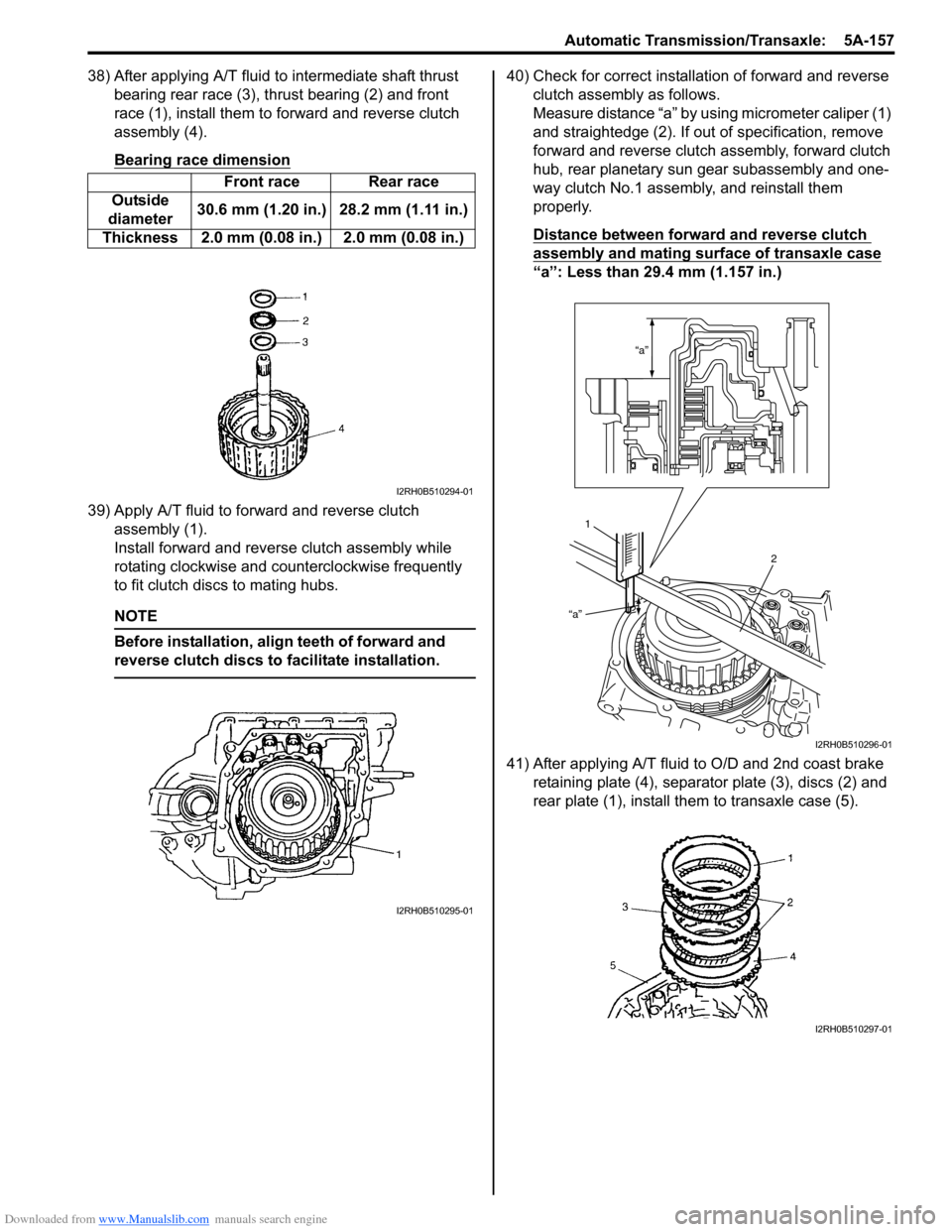
38) After applying A/T fluid to intermediate shaft thrust bearing rear race (3), thrust bearing (2) and front
race (1), install them to forward and reverse clutch
assembly (4).
Bearing race dimension
39) Apply A/T fluid to forward and reverse clutch assembly (1).
Install forward and revers e clutch assembly while
rotating clockwise and co unterclockwise frequently
to fit clutch discs to mating hubs.
NOTE
Before installation, align teeth of forward and
reverse clutch discs to facilitate installation.
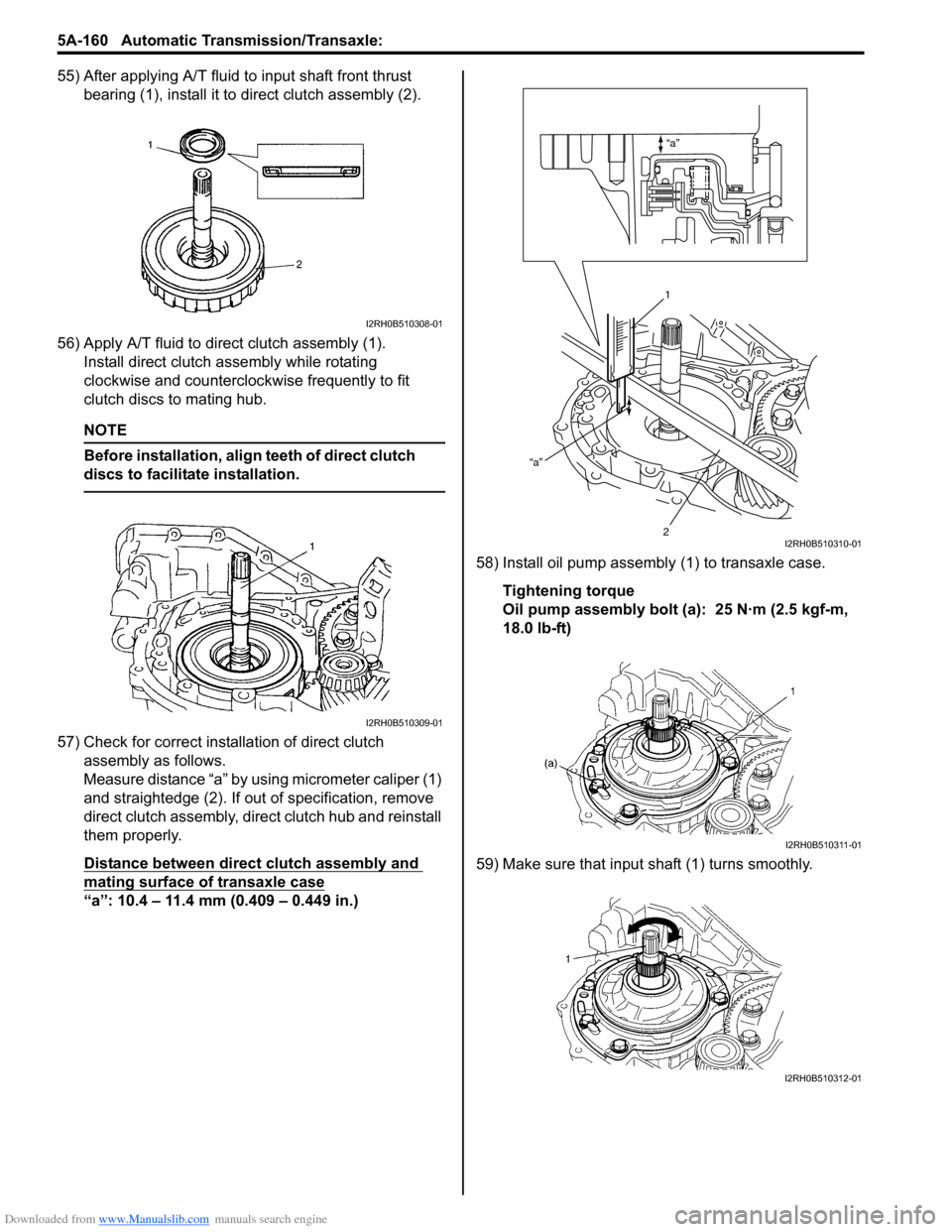
40) Check for correct installation of forward and reverse clutch assembly as follows.
Measure distance “a” by using micrometer caliper (1)
and straightedge (2). If out of specification, remove
forward and reverse clutch assembly, forward clutch
hub, rear planetary sun gear subassembly and one-
way clutch No.1 assemb ly, and reinstall them
properly.
Distance between forward and reverse clutch
assembly and mating surface of transaxle case
“a”: Less than 29.4 mm (1.157 in.)
41) After applying A/T fluid to O/D and 2nd coast brake retaining plate (4), separator plate (3), discs (2) and
rear plate (1), install th em to transaxle case (5).
Front race Rear race
Outside
diameter 30.6 mm (1.20 in.) 28.2 mm (1.11 in.)
Thickness 2.0 mm (0.08 in.) 2.0 mm (0.08 in.)
I2RH0B510294-01
I2RH0B510295-01
“a”
“a”
1 2
I2RH0B510296-01
I2RH0B510297-01
Page 804 of 1496

Downloaded from www.Manualslib.com manuals search engine 5A-160 Automatic Transmission/Transaxle:
55) After applying A/T fluid to input shaft front thrust bearing (1), install it to direct clutch assembly (2).
56) Apply A/T fluid to direct clutch assembly (1). Install direct clutch a ssembly while rotating
clockwise and counterclockwise frequently to fit
clutch discs to mating hub.
NOTE
Before installation, align teeth of direct clutch
discs to facilitate installation.
57) Check for correct installation of direct clutch assembly as follows.
Measure distance “a” by using micrometer caliper (1)
and straightedge (2). If out of specification, remove
direct clutch assembly, direct clutch hub and reinstall
them properly.
Distance between direct clutch assembly and
mating surface of transaxle case
“a”: 10.4 – 11.4 mm (0.409 – 0.449 in.) 58) Install oil pump assembly
(1) to transaxle case.
Tightening torque
Oil pump assembly bolt (a): 25 N·m (2.5 kgf-m,
18.0 lb-ft)
59) Make sure that input shaft (1) turns smoothly.
I2RH0B510308-01
I2RH0B510309-01
“a”
“a”
1
2
I2RH0B510310-01
I2RH0B510311-01
I2RH0B510312-01
Page 806 of 1496

Downloaded from www.Manualslib.com manuals search engine 5A-162 Automatic Transmission/Transaxle:
66) After applying A/T fluid to new O-ring, fit it to transaxle case plug (1). Then install the transaxle
case plug to transaxle case (2).
Tightening torque
Transaxle case plug (a): 7.5 N·m (0.75 kgf-m, 5.5
lb-ft)
67) Install new O-rings to each accumulator piston and apply A/T fluid to them.
Accumulator O-ri ng dimension
NOTE
Make sure that O-rings are not twisted or
caught when installing.
68) Install B1, C1, C2 accumulator pistons and springs.
Accumulator piston identification
Accumulator spring identification
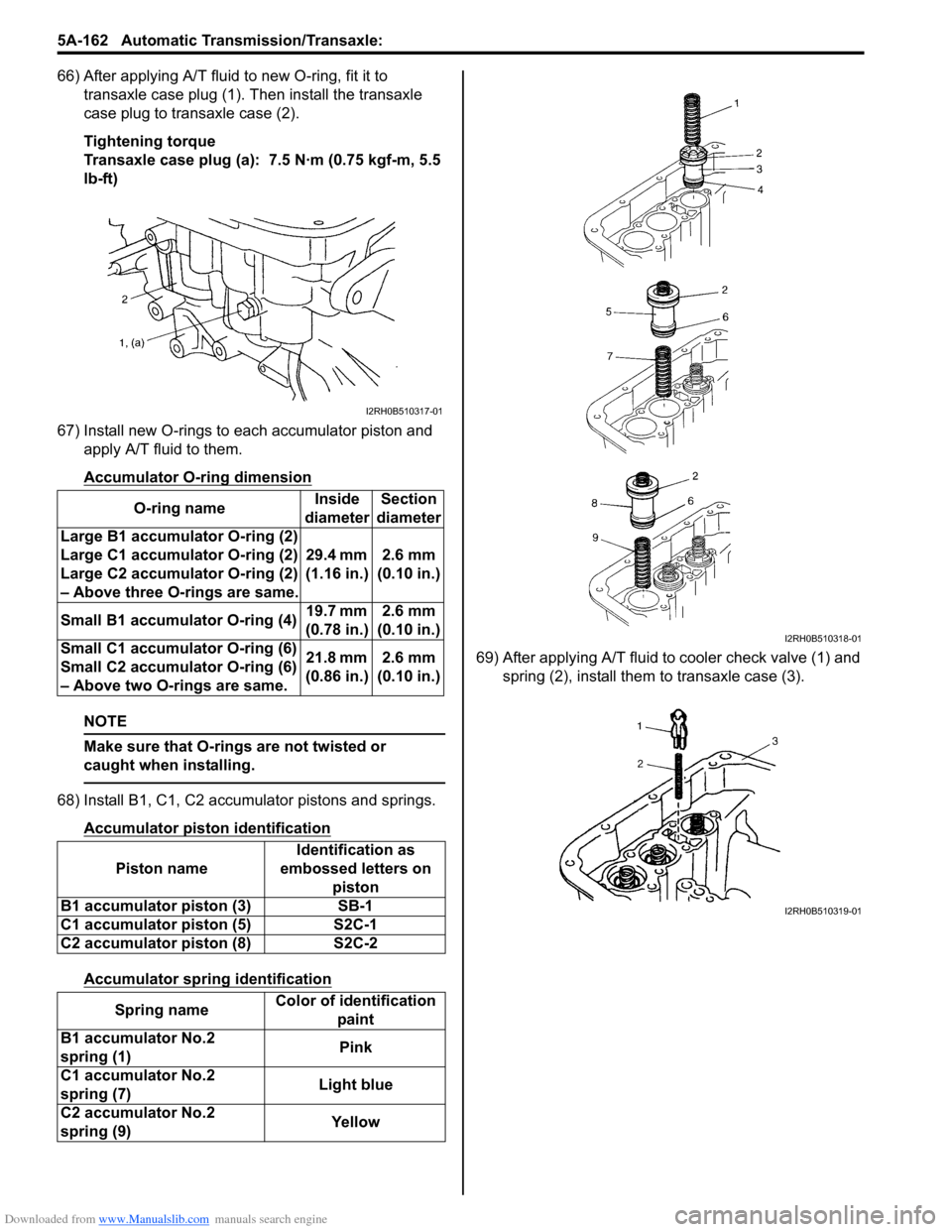
69) After applying A/T fluid to cooler check valve (1) and
spring (2), install them to transaxle case (3).
O-ring name
Inside
diameter Section
diameter
Large B1 accumula tor O-ring (2)
Large C1 accumula tor O-ring (2)
Large C2 accumula tor O-ring (2)
– Above three O-rings are same. 29.4 mm
(1.16 in.) 2.6 mm
(0.10 in.)
Small B1 accumulator O-ring (4) 19.7 mm
(0.78 in.) 2.6 mm
(0.10 in.)
Small C1 accumulator O-ring (6)
Small C2 accumulator O-ring (6)
– Above two O-rings are same. 21.8 mm
(0.86 in.) 2.6 mm
(0.10 in.)
Piston name Identification as
embossed letters on piston
B1 accumulator piston (3) SB-1
C1 accumulator piston (5) S2C-1
C2 accumulator piston (8) S2C-2
Spring name Color of identification
paint
B1 accumulator No.2
spring (1) Pink
C1 accumulator No.2
spring (7) Light blue
C2 accumulator No.2
spring (9) Yellow
I2RH0B510317-01
I2RH0B510318-01
I2RH0B510319-01
Page 853 of 1496

Downloaded from www.Manualslib.com manuals search engine Clutch: 5C-1
Transmission / Transaxle
Clutch
General Description
Clutch ConstructionS7RS0B5301001
The clutch is a diaphragm spring clutch of a dry single disc type. The diaphragm spring is of a tapering-finger type,
which is a solid ring in the outer diameter part, with a series of tapered fingers pointing inward.
The disc, carrying four torsional coil springs, is positione d on the transaxle input shaft with an involute spline fit.
The clutch cover is secured to the flywheel, and carries the diaphragm spring in such a way that the peripheral edge
part of the spring pushes on the pressure plate against the flywheel (with the disc in between), when the clutch release
bearing is held back. This is the engaged condition of the clutch.
Depressing the clutch pedal c auses the release bearing to advance and pushes on the tips of the tapered fingers of
the diaphragm spring. When this happens, the diaphragm sp ring pulls the pressure plate away from the flywheel,
thereby interrupting the flow of drive from flywheel through clutch disc to transaxle input shaft. Clutch fluid is supplied
from brake fluid reservoir. Clutch fluid level can be checked by brake fluid level of brake fluid reservoir.
[A]: For petrol engine model2. Flywheel5. Clutch cover 8. Input shaft bearing
[B]: For diesel engine model 3. Clutch disc6. Diaphragm spring 9. Input shaft
1. Crankshaft 4. Pressure plate7. Release bearing 10. Release shaft
I4RS0A530001-01