2005 SUZUKI SWIFT gear ratio
[x] Cancel search: gear ratioPage 42 of 1496

Downloaded from www.Manualslib.com manuals search engine 0B-12 Maintenance and Lubrication:
HVAC Air Filter (If Equipped) InspectionS7RS0B0206032
1) Remove HVAC air filter from HVAC unit referring to
“HVAC Air Filter Removal and Installation (If
Equipped) in Section 7A”.
2) Check for dirt and dust. If HVAC air filter is excessively dirty, replace HVAC air filter with new
one. If not, go to next step.
3) Blow compressed air on the air outlet side of HVAC air filter for removing dust.
4) Install HVAC air filter in to HVAC unit referring to
“HVAC Air Filter Removal and Installation (If
Equipped) in Section 7A”.
HVAC Air Filter (If Equipped) ReplacementS7RS0B0206033
Replace HVAC air filter with new one referring to “HVAC
Air Filter Removal and Installation (If Equipped) in
Section 7A”.
Final Inspection for Maintenance ServiceS7RS0B0206034
WARNING!
When carrying out road tests, select a safe
place where no man or no running vehicle is
seen so as to prevent any accident.
Seats
Check that seat slides smoot hly and locks securely at
any position. Also check that reclining mechanism of
front seat back allows it to be locked at any angle.
Seat Belt
Inspect belt system including webbing, buckles, latch
plates, retractors and anchors for damage or wear.
Check that seat belt is securely locked. If “REPLACE
BELT” label on seat belt is visible, replace belt.
Battery Electrolyte Level Check
Check that the electrolyte le vel of all battery cells is
between the upper and lower level lines on the case. If
battery is equipped with built-in indicator, check battery
condition by the indicator. Accelerator Pedal Operation
Check that pedal operates
smoothly without getting
caught or interfered by any other part.
Engine Start
Check engine start for readiness.
WARNING!
Before performing th e following check, be
sure to have enough room around the
vehicle. Then, firmly apply both the parking
brake and the regular brakes. Do not use the
accelerator pedal. If the engine starts, be
ready to turn off the ignition promptly. Take
these precautions because the vehicle could
move without warning and possibly cause
personal injury or property damage.
On automatic transaxle vehicles, try to start the engine in
each select lever position. The starting motor should
crank only in “P” (Park) or “N” (Neutral).
On manual transaxle vehicles, place the shift lever in
“Neutral,” depress clutch pedal fully and try to start.
On Automated Manual Transaxl e vehicles, try to start
the engine in each select le ver position. The starting
motor should crank only when select lever is in “N”
(Neutral) and brake pedal is depressed.
Exhaust System Check
Check for leakage, cracks or loose supports.
Clutch (for Manual Transaxle)
Check for the following.
• Clutch is completely released when depressing clutch pedal,
• No slipping clutch occurs when releasing pedal and accelerating.
• Clutch itself is free fr om any abnormal condition.
Gearshift or Select Lever (Transaxle)
Check gear shift or select lever for smooth shifting to all
positions and for good performance of transaxle in any
position.
With automatic transaxle or Automated Manual
Transaxle equipped vehicle, also check that shift
indicator indicates properly according to which position
select lever is shifted to.
With automatic transaxle equipped vehicle, make sure
that vehicle is at complete stop when shifting select lever
to “P” range position and release all brakes.
I4RS0A020018-01
Page 83 of 1496
Downloaded from www.Manualslib.com manuals search engine Engine General Information and Diagnosis: 1A-33
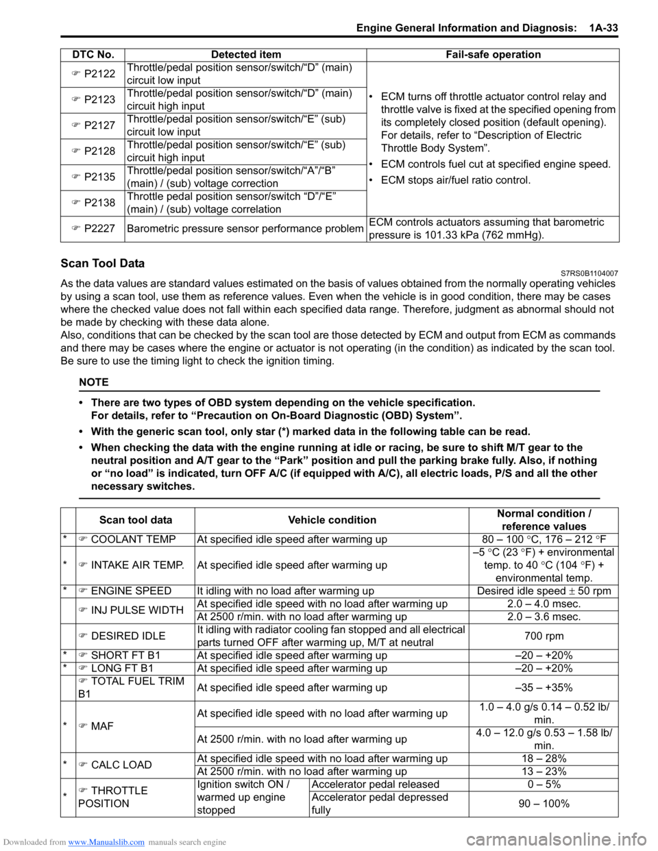
Scan Tool DataS7RS0B1104007
As the data values are standard values estimated on the basis of values obtained from the normally operating vehicles
by using a scan tool, use them as re ference values. Even when the vehicle is in good condition, there may be cases
where the checked value does not fall within each specified data range. Therefore, judgment as abnormal should not
be made by checking with these data alone.
Also, conditions that can be checked by the scan tool are those detected by ECM and output from ECM as commands
and there may be cases where the engine or actuator is not operating (in the condition) as indicated by the scan tool.
Be sure to use the timing light to check the ignition timing.
NOTE
• There are two types of OBD system depending on the vehicle specification.
For details, refer to “Precaution on On-Board Diagnostic (OBD) System”.
• With the generic scan tool, only star (*) marked data in the following table can be read.
• When checking the data with the engine running at idle or racing, be sure to shift M/T gear to the neutral position and A/T gear to the “Park” position and pull the parking brake fully. Also, if nothing
or “no load” is indicated, turn O FF A/C (if equipped with A/C), all electric loads, P/S and all the other
necessary switches.
�) P2122 Throttle/pedal position sensor/switch/“D” (main)
circuit low input
• ECM turns off throttle actuator control relay and throttle valve is fixed at the specified opening from
its completely closed position (default opening).
For details, refer to “Description of Electric
Throttle Body System”.
• ECM controls fuel cut at specified engine speed.
• ECM stops air/fuel ratio control.
�)
P2123 Throttle/pedal position sensor/switch/“D” (main)
circuit high input
�) P2127 Throttle/pedal position sensor/switch/“E” (sub)
circuit low input
�) P2128 Throttle/pedal position sensor/switch/“E” (sub)
circuit high input
�) P2135 Throttle/pedal position sensor/switch/“A”/“B”
(main) / (sub) voltage correction
�) P2138 Throttle pedal position sensor/switch “D”/“E”
(main) / (sub) voltage correlation
�) P2227 Barometric pressure sensor performance problem ECM controls actuators assuming that barometric
pressure is 101.33 kPa (762 mmHg).
DTC No. Detected item Fail-safe operation
Scan tool data
Vehicle condition Normal condition /
reference values
* �) COOLANT TEMP At specified idle speed after warming up 80 – 100 °C, 176 – 212 °F
* �) INTAKE AIR TEMP. At specifie d idle speed after warming up –5
°C (23 °F) + environmental
temp. to 40 °C (104 °F) +
environmental temp.
* �) ENGINE SPEED It idling with no load after warming upDesired idle speed ± 50 rpm
�) INJ PULSE WIDTH At specified idle speed with no load after warming up
2.0 – 4.0 msec.
At 2500 r/min. with no load after warming up 2.0 – 3.6 msec.
�) DESIRED IDLE It idling with radiator cooling fan stopped and all electrical
parts turned OFF after warming up, M/T at neutral 700 rpm
* �) SHORT FT B1 At specified idle speed after warming up –20 – +20%
* �) LONG FT B1 At specified idle speed after warming up –20 – +20%
�) TOTAL FUEL TRIM
B1 At specified idle speed after warming up
–35 – +35%
* �) MAF At specified idle speed wit
h no load after warming up 1.0 – 4.0 g/s 0.14 – 0.52 lb/
min.
At 2500 r/min. with no load after warming up 4.0 – 12.0 g/s 0.53 – 1.58 lb/
min.
* �) CALC LOAD At specified idle speed with no load after warming up
18 – 28%
At 2500 r/min. with no load after warming up 13 – 23%
* �)
THROTTLE
POSITION Ignition switch ON /
warmed up engine
stoppedAccelerator pedal released
0 – 5%
Accelerator pedal depressed
fully 90 – 100%
Page 109 of 1496
Downloaded from www.Manualslib.com manuals search engine Engine General Information and Diagnosis: 1A-59
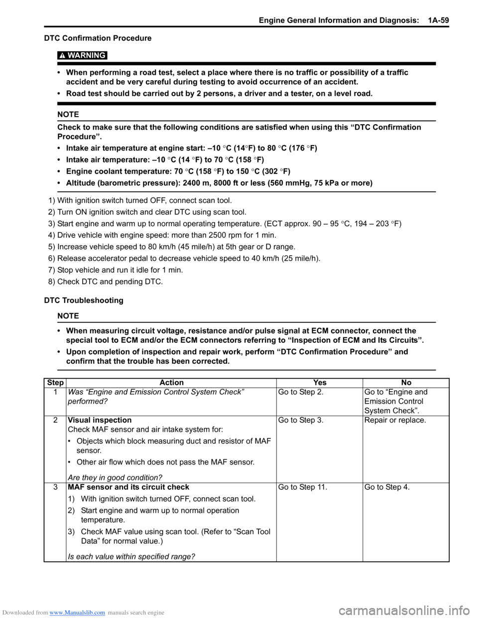
DTC Confirmation Procedure
WARNING!
• When performing a road test, select a place where there is no traffic or possibility of a traffic accident and be very careful during testing to avoid occurrence of an accident.
• Road test should be carried out by 2 persons, a driver and a tester, on a level road.
NOTE
Check to make sure that the following conditions are satisfied when using this “DTC Confirmation
Procedure”.
• Intake air temperature at engine start: –10 °C (14 °F) to 80 °C (176 °F)
• Intake air temperature: –10 °C (14 °F) to 70 °C (158 °F)
• Engine coolant temperature: 70 °C (158 °F) to 150 °C (302 °F)
• Altitude (barometric pressure): 2400 m, 8000 ft or less (560 mmHg, 75 kPa or more)
1) With ignition switch turned OFF, connect scan tool.
2) Turn ON ignition switch and clear DTC using scan tool.
3) Start engine and warm up to normal operating temperature. (ECT approx. 90 – 95 °C, 194 – 203 °F)
4) Drive vehicle with engine speed: more than 2500 rpm for 1 min.
5) Increase vehicle speed to 80 km/h (45 mile/h) at 5th gear or D range.
6) Release accelerator pedal to decrease vehicle speed to 40 km/h (25 mile/h).
7) Stop vehicle and run it idle for 1 min.
8) Check DTC and pending DTC.
DTC Troubleshooting
NOTE
• When measuring circuit voltage, resistance and/ or pulse signal at ECM connector, connect the
special tool to ECM and/or the ECM connectors re ferring to “Inspection of ECM and Its Circuits”.
• Upon completion of inspection and repair work, perform “DTC Confirmation Procedure” and confirm that the trouble has been corrected.
Step Action YesNo
1 Was “Engine and Emission Control System Check”
performed? Go to Step 2.
Go to “Engine and
Emission Control
System Check”.
2 Visual inspection
Check MAF sensor and air intake system for:
• Objects which block measuring duct and resistor of MAF
sensor.
• Other air flow which does not pass the MAF sensor.
Are they in good condition? Go to Step 3.
Repair or replace.
3 MAF sensor and its circuit check
1) With ignition switch turned OFF, connect scan tool.
2) Start engine and warm up to normal operation
temperature.
3) Check MAF value using scan tool. (Refer to “Scan Tool Data” for normal value.)
Is each value within specified range? Go to Step 11. Go to Step 4.
Page 179 of 1496
Downloaded from www.Manualslib.com manuals search engine Engine General Information and Diagnosis: 1A-129
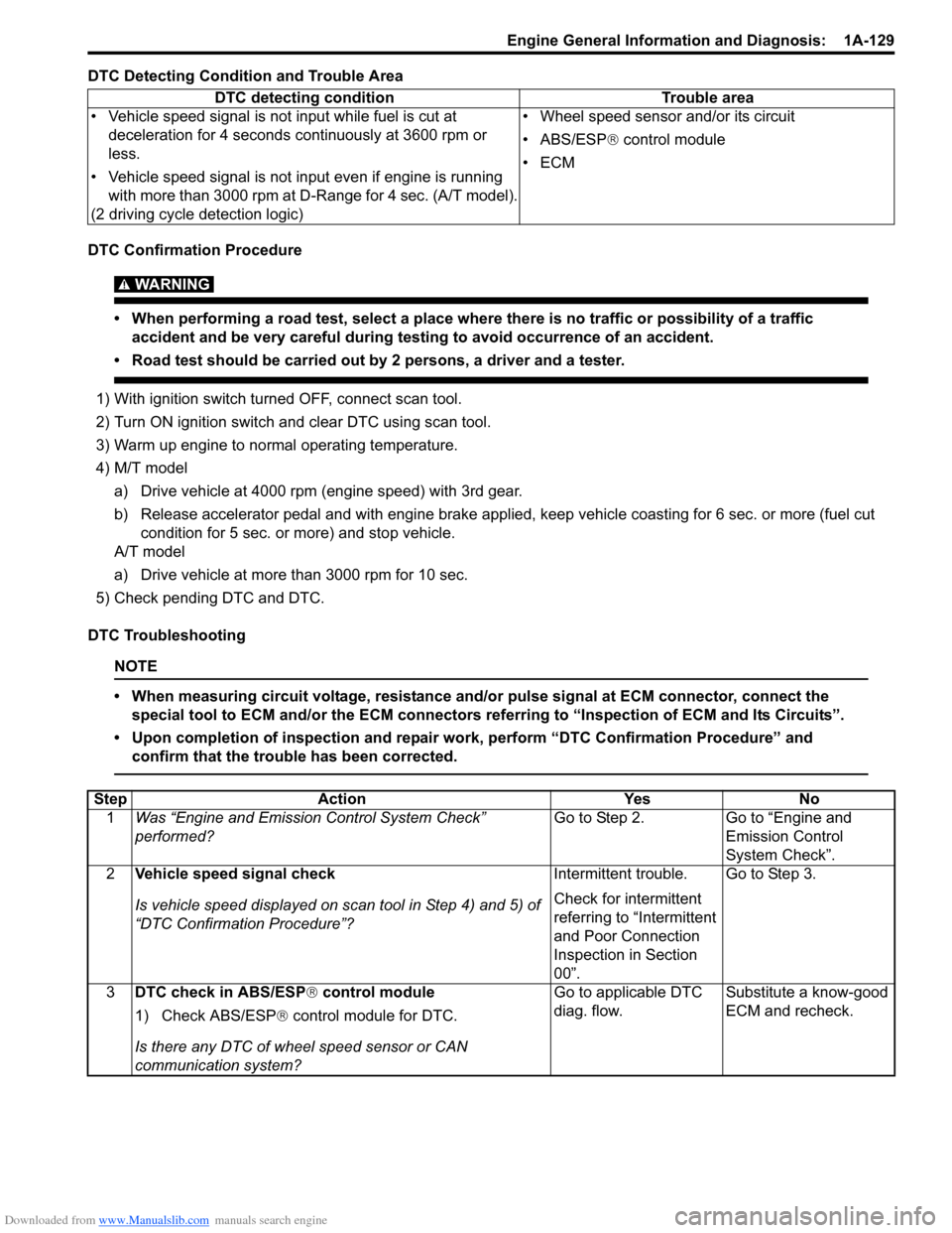
DTC Detecting Condition and Trouble Area
DTC Confirmation Procedure
WARNING!
• When performing a road test, select a place where there is no traffic or possibility of a traffic accident and be very careful during testing to avoid occurrence of an accident.
• Road test should be carried out by 2 persons, a driver and a tester.
1) With ignition switch turned OFF, connect scan tool.
2) Turn ON ignition switch and clear DTC using scan tool.
3) Warm up engine to normal operating temperature.
4) M/T model
a) Drive vehicle at 4000 rpm (e ngine speed) with 3rd gear.
b) Release accelerator pedal and with engine brake applied, keep vehicle coasting for 6 sec. or more (fuel cut condition for 5 sec. or more) and stop vehicle.
A/T model
a) Drive vehicle at more than 3000 rpm for 10 sec.
5) Check pending DTC and DTC.
DTC Troubleshooting
NOTE
• When measuring circuit voltage, resistance and/ or pulse signal at ECM connector, connect the
special tool to ECM and/or the ECM connectors re ferring to “Inspection of ECM and Its Circuits”.
• Upon completion of inspection and repair work, perform “DTC Confirmation Procedure” and confirm that the trouble has been corrected.
DTC detecting condition Trouble area
• Vehicle speed signal is not input while fuel is cut at deceleration for 4 seconds continuously at 3600 rpm or
less.
• Vehicle speed signal is not input even if engine is running with more than 3000 rpm at D-Range for 4 sec. (A/T model).
(2 driving cycle detection logic) • Wheel speed sensor and/or its circuit
• ABS/ESP®
control module
•ECM
Step Action YesNo
1 Was “Engine and Emission Control System Check”
performed? Go to Step 2.
Go to “Engine and
Emission Control
System Check”.
2 Vehicle speed signal check
Is vehicle speed displayed on scan tool in Step 4) and 5) of
“DTC Confirmation Procedure”? Intermittent trouble.
Check for intermittent
referring to “Intermittent
and Poor Connection
Inspection in Section
00”.Go to Step 3.
3 DTC check in ABS/ESP ® control module
1) Check ABS/ESP ® control module for DTC.
Is there any DTC of wheel speed sensor or CAN
communication system? Go to applicable DTC
diag. flow.
Substitute a know-good
ECM and recheck.
Page 194 of 1496

Downloaded from www.Manualslib.com manuals search engine 1A-144 Engine General Information and Diagnosis:
DTC Troubleshooting
NOTE
• When measuring circuit voltage, resistance and/or pulse signal at ECM connector, connect the
special tool to ECM and/or the ECM connectors re ferring to “Inspection of ECM and Its Circuits”.
• Upon completion of inspection and repair work, perform “DTC Confirmation Procedure” and confirm that the trouble has been corrected.
DTC P1603: TCM Trouble Code DetectedS7RS0B1104061
Wiring Diagram
DTC Detecting Condition
When ECM receives a trouble code from TCM, which indicates that some problem occurred in sensor circuits and its
calculated values used for operations such as idle speed control, engine power control, and so on by TCM, ECM sets
DTC P1603. (TCM outputs the trouble code to ECM when TCM can not compute the engine control signal due to
malfunctions of sensor circuits used for gear shift control.) Step Action Yes No
1 Was “Engine and Emission Control System Check”
performed? Go to Step 2. Go to “Engine and
Emission Control
System Check”.
2 Battery voltage supply circuit check
1) Turn OFF ignition switch.
2) Remove ECM from its br acket with ECM connectors
connected.
3) With engine running, measure voltage between “E23-2” terminal of ECM connector and engine ground.
Is voltage 10 – 14 V? Poor “E23-2”
connection or
intermittent trouble.
Check for intermittent
referring to “Intermittent
and Poor Connection
Inspection in Section
00”.
If wire and connections
are OK, substitute a
known-good ECM and
recheck.“RADIO” fuse blown,
“WHT” or “WHT/RED”
wire is circuit open or
short circuit.
E23
C37
34
1819
567
1011
17
20
47 46
495051
2122
52 16
25 9
24
14
29
55
57 54 53
59
60 58 2
262728
15
30
56 4832 31
34353637
40
42 39 38
44
45 43 41 331
1213
238
34
1819
567
1011
17
20
47 46
495051
2122
52 16
25 9
24
14
29
55
57 54 53
59
60 58 2
262728
15
30
56 4832 31
34353637
40
42 39 38
44
45 43 41 331
1213
238
1
RED
WHT
C37-13
C37-12
RED
WHTC34-7
C34-17
2
I6RS0C110026-01
1. ECM
2. TCM (for A/T model)
Page 274 of 1496
Downloaded from www.Manualslib.com manuals search engine 1C-2 Engine Electrical Devices:
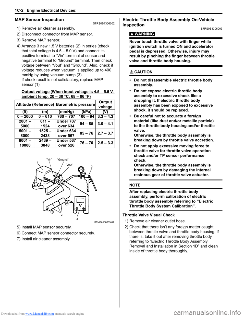
MAP Sensor InspectionS7RS0B1306002
1) Remove air cleaner assembly.
2) Disconnect connector from MAP sensor.
3) Remove MAP sensor.
4) Arrange 3 new 1.5 V batteries (2) in series (check that total voltage is 4.5 – 5.0 V) and connect its
positive terminal to “Vin ” terminal of sensor and
negative terminal to “Ground” terminal. Then check
voltage between “Vout” and “Ground”. Also, check if
voltage reduces when vacuum is applied up to 400
mmHg by using vacuum pump (3).
If check result is not satisfactory, replace MAP
sensor (1).
Output voltage (When input voltage is 4.5 – 5.5 V,
ambient temp. 20 – 30 °C, 68 – 86 °F)
5) Install MAP sensor securely.
6) Connect MAP sensor connector securely.
7) Install air cleaner assembly.
Electric Throttle Body Assembly On-Vehicle
Inspection
S7RS0B1306003
WARNING!
Never touch throttle valve with finger while
ignition switch is turned ON and accelerator
pedal is depressed. Otherwise, injury may
result by pinching the finger between throttle
valve and throttle body housing.
CAUTION!
• Do not disassemble electric throttle body assembly.
• Do not expose electric throttle body assembly to excessive shock like a
dropping it. If electric throttle body
assembly has been exposed to excessive
shock, it should be replaced.
• Be careful not to accurate a foreign material (like dust and/ or metallic particle)
to the throttle body housing and/or throttle
valve.
Otherwise, the throttle body assembly is
breaking down by throttle valve accretion.
• Do not apply excessive moving force to throttle valve for thro ttle valve operation
check and/or TP sensor performance
check.
Otherwise, the throttle body assembly is
breaking down by damaging the internal
resinous gear of throttle valve actuator.
NOTE
After replacing electric throttle body
assembly, perform calibration of electric
throttle body assembly referring to “Electric
Throttle Body System Calibration”.
Throttle Valve Visual Check
1) Remove air cleaner outlet hose.
2) Check that there isn’t any foreign matter caught between throttle valve and throttle body housing. If
there is, take it out after removing throttle body
referring to “Electric Th rottle Body Assembly
Removal and Installation in Section 1D” and clean
inside of throttle body thoroughly.
Altitude (Reference) Barometric pressure
Output
voltage
(ft) (m) (mmHg) (kPa) (V)
0 – 2000 0 – 610 760 – 707 100 – 94 3.3 – 4.3 2001 – 5000 611 –
1524 Under 707
over 634 94 – 85 3.0 – 4.1
5001 – 8000 1525 –
2438 Under 634
over 567 85 – 76 2.7 – 3.7
8001 – 10000 2439 –
3048 Under 567
over 526 76 – 70 2.5 – 3.3
I3RM0A130005-01
Page 289 of 1496
Downloaded from www.Manualslib.com manuals search engine Engine Mechanical: 1D-4
Targeted Timing Varying Operation
Diagnostic Information and Procedures
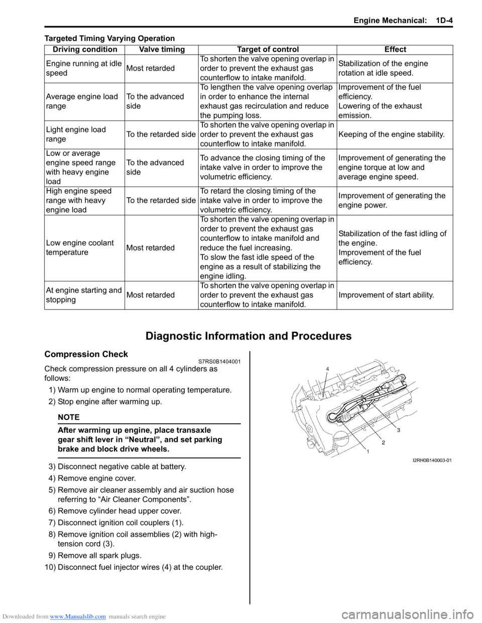
Compression CheckS7RS0B1404001
Check compression pressure on all 4 cylinders as
follows:
1) Warm up engine to normal operating temperature.
2) Stop engine after warming up.
NOTE
After warming up engine, place transaxle
gear shift lever in “Neutral”, and set parking
brake and block drive wheels.
3) Disconnect negative cable at battery.
4) Remove engine cover.
5) Remove air cleaner assembly and air suction hose referring to “Air Cleaner Components”.
6) Remove cylinder head upper cover.
7) Disconnect ignition coil couplers (1).
8) Remove ignition coil assemblies (2) with high- tension cord (3).
9) Remove all spark plugs.
10) Disconnect fuel injector wires (4) at the coupler. Driving condition Valve timing Target of control Effect
Engine running at idle
speed Most retardedTo shorten the valve opening overlap in
order to prevent the exhaust gas
counterflow to in
take manifold. Stabilization of the engine
rotation at idle speed.
Average engine load
range To the advanced
sideTo lengthen the valve opening overlap
in order to enhance the internal
exhaust gas recirculation and reduce
the pumping loss. Improvement of the fuel
efficiency.
Lowering of the exhaust
emission.
Light engine load
range To the retarded sideTo shorten the valve opening overlap in
order to prevent the exhaust gas
counterflow to in
take manifold. Keeping of the engine stability.
Low or average
engine speed range
with heavy engine
load To the advanced
side
To advance the closing timing of the
intake valve in order to improve the
volumetric efficiency. Improvement of generating the
engine torque at low and
average engine speed.
High engine speed
range with heavy
engine load To the retarded sideTo retard the closing timing of the
intake valve in order to improve the
volumetric efficiency. Improvement of generating the
engine power.
Low engine coolant
temperature Most retardedTo shorten the valve opening overlap in
order to prevent the exhaust gas
counterflow to intake manifold and
reduce the fuel increasing.
To slow the fast idle speed of the
engine as a result of stabilizing the
engine idling. Stabilization of the fast idling of
the engine.
Improvement of the fuel
efficiency.
At engine starting and
stopping Most retardedTo shorten the valve opening overlap in
order to prevent the exhaust gas
counterflow to in
take manifold. Improvement of start ability.I2RH0B140003-01
Page 302 of 1496

Downloaded from www.Manualslib.com manuals search engine 1D-17 Engine Mechanical:
Engine Assembly Removal and InstallationS7RS0B1406011
NOTE
After replacing electric throttle body
assembly, perform calibration of throttle
valve referring to “Electric Throttle Body
System Calibration in Section 1C”.
Removal1) Relieve fuel pressure according to “Fuel Pressure Relief Procedure in Section 1G”.
2) Disconnect negative and pos itive cable at battery.
3) Remove battery and tray.
4) Remove engine hood after disconnecting windshield washer hose.
5) Remove right and left side engine under covers.
6) Remove A/C compressor belt by referring to “Compressor Drive Belt Remo val and Installation in
Section 7B” or “Compressor Drive Belt Removal and
Installation in Section 7B”.
7) Drain engine oil, transaxle oil and coolant.
8) Remove cowl top plate referring to “Cowl Top Components in Section 9K”.
9) Remove air cleaner assembly referring to “Air Cleaner Components”.
10) With hose connected, detach A/C compressor from its bracket (A/C model) referring to “Compressor
Assembly Removal and Installation in Section 7B” or
“Compressor Assembly Removal and Installation in
Section 7B”.
CAUTION!
Suspend removed A/C compressor at a place
where no damage will be caused during
removal and installation of engine assembly.
11) Remove intake manifold rear stiffener (1) from intake manifold and cylinder block. 12) Disconnect the following electric wires:
• MAP sensor (1)
• ECT sensor (2)
•EGR valve (3)
• CMP sensor (4)
• Electric throttle body assembly (5)
• Ignition coil assembly (6)
• Injectors (7)
• Heated oxygen sensor No. 2 (8) and No. 1 (9)
• Oil control valve (10)
• Engine oil pressure switch (11)
• CKP sensor (12)
• Knock sensor (13)
• Back up light switch (14)
• Generator (15)
• Starting motor (16)
• Ground terminal (17) from intake manifold
• Battery ground terminal (18) from exhaust manifold
• Battery ground cable (19) from transaxle
• Magnet clutch switch of A/C compressor (A/C model)
• Each wire harness clamps
• Output shaft speed sensor (VSS) (34) (A/T model)
• Solenoid valve (33) (A/T model)
• Transmission range sensor (32) (A/T model)
• Input shaft speed sensor (31) (A/T model)
13) Remove fuse box from its bracket.
14) Disconnect the following cables: • Gear select control cable (23) (M/T model)
• Gear shift control cable (24) (M/T model)
• A/T select cable (A/T model)
15) Disconnect the following hoses: • Brake booster hose (26) from intake manifold
• Radiator inlet and outlet hoses (20) from each pipe
• Heater inlet and outlet hoses (21) from each pipe
• Fuel feed hoses (22) from fuel feed pipe
• EVAP canister purge valve hose (30) from purge pipe
• A/T fluid cooler hoses (A/T model)
16) With hose connected, detach clutch operating cylinder (25). (M/T model)
CAUTION!
Suspend removed clutch operating cylinder
at a place where no damage will be caused
during removal and installation of engine
assembly.
1
I6RS0B141014-01