2005 SUZUKI SWIFT 1a 120
[x] Cancel search: 1a 120Page 1148 of 1496
Downloaded from www.Manualslib.com manuals search engine 8B-110 Air Bag System:
Installation
CAUTION!
Proper operation of forward-sensor requires
sensor be rigidly attached to vehicle
structure and that the arrow on sensor be
pointing toward the front of the vehicle.
1) Check that none of the following faulty conditions exists.
• Bend, deformity or rust of front panel.
• Foreign matter on mating surface of sensor.
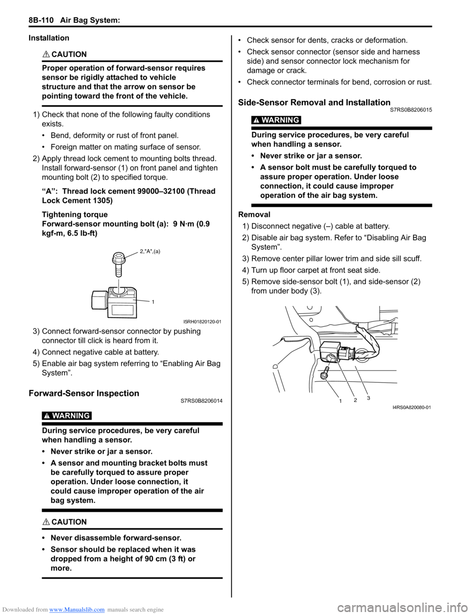
2) Apply thread lock cement to mounting bolts thread. Install forward-sensor (1) on front panel and tighten
mounting bolt (2) to specified torque.
“A”: Thread lock cement 99000–32100 (Thread
Lock Cement 1305)
Tightening torque
Forward-sensor mounting bolt (a): 9 N·m (0.9
kgf-m, 6.5 lb-ft)
3) Connect forward-sensor connector by pushing connector till click is heard from it.
4) Connect negative cable at battery.
5) Enable air bag system referring to “Enabling Air Bag System”.
Forward-Sensor InspectionS7RS0B8206014
WARNING!
During service procedures, be very careful
when handling a sensor.
• Never strike or jar a sensor.
• A sensor and mounting bracket bolts must be carefully torqued to assure proper
operation. Under loose connection, it
could cause improper operation of the air
bag system.
CAUTION!
• Never disassemble forward-sensor.
• Sensor should be replaced when it was dropped from a height of 90 cm (3 ft) or
more.
• Check sensor for dents, cracks or deformation.
• Check sensor connector (sensor side and harness side) and sensor connector lock mechanism for
damage or crack.
• Check connector terminals for bend, corrosion or rust.
Side-Sensor Removal and InstallationS7RS0B8206015
WARNING!
During service procedures, be very careful
when handling a sensor.
• Never strike or jar a sensor.
• A sensor bolt must be carefully torqued to assure proper operation. Under loose
connection, it could cause improper
operation of the air bag system.
Removal
1) Disconnect negative (–) cable at battery.
2) Disable air bag system. Re fer to “Disabling Air Bag
System”.
3) Remove center pillar lowe r trim and side sill scuff.
4) Turn up floor carpet at front seat side.
5) Remove side-sensor bolt (1), and side-sensor (2) from under body (3).
2,"A",(a)
1
I5RH01820120-01
1 23I4RS0A820080-01
Page 1158 of 1496
Downloaded from www.Manualslib.com manuals search engine 8B-120 Air Bag System:
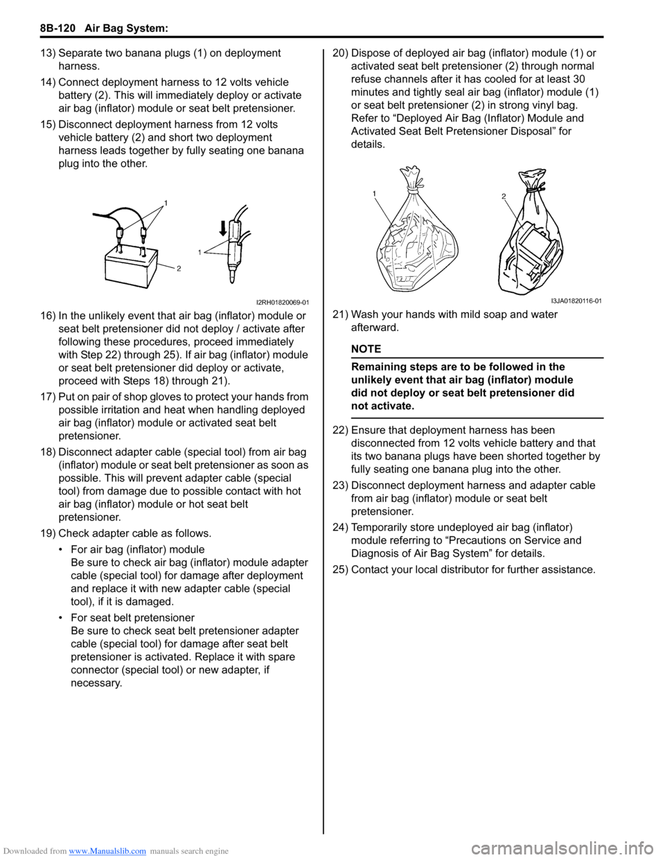
13) Separate two banana plugs (1) on deployment harness.
14) Connect deployment harness to 12 volts vehicle battery (2). This will immedi ately deploy or activate
air bag (inflator) module or seat belt pretensioner.
15) Disconnect deployment harness from 12 volts vehicle battery (2) and short two deployment
harness leads together by fully seating one banana
plug into the other.
16) In the unlikely event that air bag (inflator) module or seat belt pretensioner did not deploy / activate after
following these procedur es, proceed immediately
with Step 22) through 25). If air bag (inflator) module
or seat belt pretensioner did deploy or activate,
proceed with Steps 18) through 21).
17) Put on pair of shop gloves to protect your hands from possible irritation and heat when handling deployed
air bag (inflator) module or activated seat belt
pretensioner.
18) Disconnect adapter cable (special tool) from air bag (inflator) module or seat belt pretensioner as soon as
possible. This will preven t adapter cable (special
tool) from damage due to possible contact with hot
air bag (inflator) module or hot seat belt
pretensioner.
19) Check adapter cable as follows. • For air bag (inflator) moduleBe sure to check air bag (inflator) module adapter
cable (special tool) for damage after deployment
and replace it with new adapter cable (special
tool), if it is damaged.
• For seat belt pretensioner Be sure to check seat belt pretensioner adapter
cable (special tool) for damage after seat belt
pretensioner is activated. Replace it with spare
connector (special tool) or new adapter, if
necessary. 20) Dispose of deployed air bag (inflator) module (1) or
activated seat belt preten sioner (2) through normal
refuse channels after it has cooled for at least 30
minutes and tightly seal air bag (inflator) module (1)
or seat belt pretensioner (2) in strong vinyl bag.
Refer to “Deployed Air B ag (Inflator) Module and
Activated Seat Belt Pretensioner Disposal” for
details.
21) Wash your hands with mild soap and water afterward.
NOTE
Remaining steps are to be followed in the
unlikely event that air bag (inflator) module
did not deploy or seat belt pretensioner did
not activate.
22) Ensure that deployment harness has been disconnected from 12 volts vehicle battery and that
its two banana plugs have been shorted together by
fully seating one banana plug into the other.
23) Disconnect deployment harness and adapter cable from air bag (inflator) module or seat belt
pretensioner.
24) Temporarily store undeployed air bag (inflator) module referring to “Precautions on Service and
Diagnosis of Air Bag System” for details.
25) Contact your local distributor for further assistance.
I2RH01820069-01I3JA01820116-01
Page 1276 of 1496
Downloaded from www.Manualslib.com manuals search engine 9A-105 Wiring Systems:
E18E19E20E21 E22
IF EQPD
E23 E24 (TO C36) E25E26
RHD
E26 E27E27E28 E29E30
LHD RHD LHD
E31 E32E33E34 E35E36
E37 (TO G35) E38 (TO G36) E39E40
E41 E42E43
E44 (TO L03) E45 (TO L02) E46E47
E48 (TO E50) E49 E50 (TO E48) E51E52
21
MCONF020198-01
12
MCONF020156-01
21
MCONF020197-01
12
3
MCONF030101-01
1
2
MCONF020013-01
123456
202116171819
78910
22232425
12
2726
13
28
313233343536
505146474849
37383940
52535455
11
41
56
42
57
43
58
1415
2930
44
60
45
59
MCONF600003-01
34
7
2
68910
121314
1716
1
5
11
15181920
MCONM200005-01
21
MCONM020043-01
21
MCONF020114-01
1
2
MCONF020170-01
21
MCONF020201-01
1
2
MCONF020169-01
1
2
345
MCONF050015-01
1
2
345
MCONF050015-01
1
2
345
MCONF050015-01
1
2
34
MCONF040004-01
1
2
34
MCONF040004-01
1
2
34
MCONF040004-01
1
2
34
MCONF040004-01
1
2
34
MCONF040004-01
1
2
34
MCONF040004-01
381371251015
14914
2611
MCONM150001-01
54 32 167910
20 19 18 17 16 15 14 13 12 118
MCONM200008-01
1 234
5 678 910
MCONF100003-01
21
MCONF020202-01
6
5
4
3
2
17
11
10
9
8 15
14
13
12 16
MCONF160034-01
CC
AABB
DE
DD
EE
MCONF120059-01
CC
AABB
DE
DD
EE
MCONF120059-01
12
34
MCONF040095-0110 1
6111415 16 171213
2
734
85
9
MCONF170009-01
12567
8
9 1011121314
34
MCONF140012-01
12
34
MCONF040009-01
21
7654
3
8
MCONM080012-01
1
2
MCONF020203-01
2
51
47 6
8
3
MCONF080014-01
1
2
MCONF020204-01
10
11 12 13 14 15 16 17 18 19 123456789
20
MCONF200021-01
Page 1278 of 1496
Downloaded from www.Manualslib.com manuals search engine 9A-107 Wiring Systems:
G24G25 G26G27 G27
G28 G29G31
IF EQPD
G32 G33G34 G35 (TO E37)
G36 (TO E38) G37G39G40
IF EQPD IF EQPD
G42 G43 (TO L51)G46
IF EQPD IF EQPDAuto A/C
G47 G48G49G50G51
Auto A/C Auto A/C Auto A/C Auto A/C Auto A/C
G52 G53G54
Auto A/C Auto A/CIF EQPD
G59
M16A
21
83
9 4
10 5
11 6
12
7
MCONF120026-01
710
56 12 34
8 9 11 12 13
MCONF130010-01
21
MCONF020111-01
12345MCONF050021-011
MCONF010121-01
1
17 2
18 3
19 4
20 5
21 6
22 7
23 8
24 9
25 10
26 11
27 12
28 13
29 14
30 15
31 16
32
MCONF320005-01
12 3
8
467 5
MCONF080002-01
AA A A A
BBBB
BB
CCC C CD DD D DD
()
MCONF220018-01
6543 21
MCONF060064-01
12345
78 11 6
12
910
MCONF120028-01
10
11 12 13 14 15 16 17 18 19 123456789
20
MCONF200020-01
14951071214
381315
2611
MCONF150002-01
10
11 12 13 14 15 16 17 18 19 123456789
20
MCONF200021-01
1234567891011
12 13 14 15 16 17 18 19 20 21 22
MCONF220009-01
54321
109876
MCONF100060-01
12
3456
MCONF060025-01
123456
212223242526
7
27
8
28
9
29
10
30
11
31
12
32
13
33
14
34
15
35
16
36
17
37
18
38
19
39
20
40
MCONF400001-01
7 654 3
21
14 13 12 11 10 9 8
MCONM140005-02
12
34
MCONF040009-01
1 2
( )MCONF020105-01
2
14 3657MCONF070002-01
1234567
MCONF070004-01
12
MCONF020268-01
12349105678
11121718192013141516MCONF200023-01
12345678
910151611121314
MCONF160009-01
21
MCONF020148-01
12345678910
MCONF100064-01
12
34567
()
MCONF070021-01
Page 1292 of 1496
Downloaded from www.Manualslib.com manuals search engine 9B-10 Lighting Systems:
Turn Signal and Hazard Warning Relay
Inspection
S7RS0B9206012
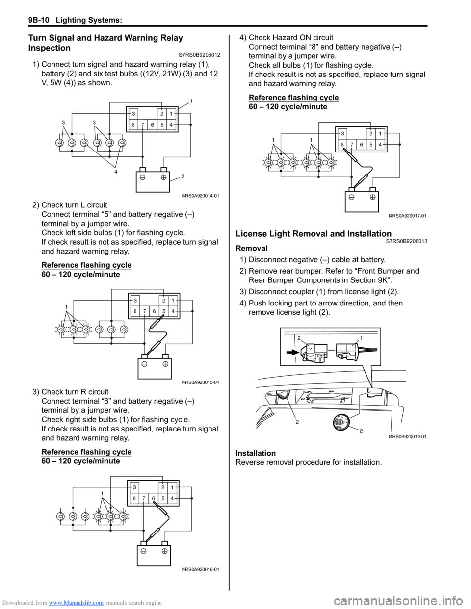
1) Connect turn signal and hazard warning relay (1), battery (2) and six test bulbs ((12V, 21W) (3) and 12
V, 5W (4)) as shown.
2) Check turn L circuit Connect terminal “5” and battery negative (–)
terminal by a jumper wire.
Check left side bulbs (1) for flashing cycle.
If check result is not as specified, replace turn signal
and hazard warning relay.
Reference flashing cycle
60 – 120 cycle/minute
3) Check turn R circuit Connect terminal “6” and battery negative (–)
terminal by a jumper wire.
Check right side bulbs (1) for flashing cycle.
If check result is not as specified, replace turn signal
and hazard warning relay.
Reference flashing cycle
60 – 120 cycle/minute 4) Check Hazard ON circuit
Connect terminal “8” and battery negative (–)
terminal by a jumper wire.
Check all bulbs (1) for flashing cycle.
If check result is not as sp ecified, replace turn signal
and hazard warning relay.
Reference flashing cycle
60 – 120 cycle/minute
License Light Removal and InstallationS7RS0B9206013
Removal
1) Disconnect negative (–) cable at battery.
2) Remove rear bumper. Refe r to “Front Bumper and
Rear Bumper Components in Section 9K”.
3) Disconnect coupler (1) from license light (2).
4) Push locking part to arrow direction, and then remove license light (2).
Installation
Reverse removal procedure for installation.
2
4
33
3
87
12
654
1
I4RS0A920014-01
13
87
12
654
I4RS0A920015-01
3
87
12
6541
I4RS0A920016-01
3
87
12
6
5411
I4RS0A920017-01
2
2
1
2
I4RS0B920010-01
Page 1384 of 1496
Downloaded from www.Manualslib.com manuals search engine 9K-7 Body Structure:
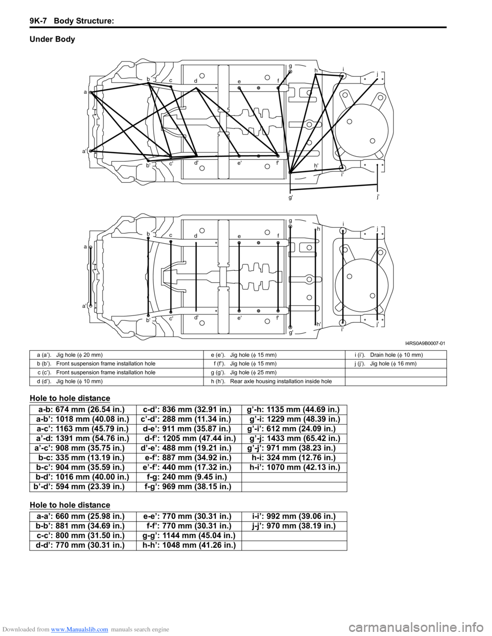
Under Body
Hole to hole distance
Hole to hole distance
ab
c d e fg
h i
j
a' b'c'
d'
e' f'
g' i'
j'
a b
c d e fg
hi
j
a' b'c'
d'
e' f'
g'h'
i' j'
h'
I4RS0A9B0007-01
a (a’). Jig hole (
φ 20 mm) e (e’). Jig hole ( φ 15 mm) i (i’). Drain hole ( φ 10 mm)
b (b’). Front suspension frame installation hole f (f’). Jig hole ( φ 15 mm) j (j’). Jig hole ( φ 16 mm)
c (c’). Front suspension frame installation hole g (g’). Jig hole (φ 25 mm)
d (d’). Jig hole ( φ 10 mm) h (h’). Rear axle housing installation inside hole
a-b: 674 mm (26.54 in.) c-d’: 836 mm (32.91 in.) g’-h: 1135 mm (44.69 in.)
a-b’: 1018 mm (40.08 in.) c’-d’: 288 mm (11.34 in.) g’-i: 1229 mm (48.39 in.) a-c’: 1163 mm (45.79 in.) d-e’: 911 mm (35.87 in.) g’-i’: 612 mm (24.09 in.)
a’-d: 1391 mm (54.76 in.) d-f’: 1205 mm (47.44 in.) g’-j: 1433 mm (65.42 in.)
a’-c’: 908 mm (35.75 in.) d’-e’: 488 mm (1 9.21 in.) g’-j’: 971 mm (38.23 in.)
b-c: 335 mm (13.19 in.) e-f’: 887 mm (34.92 in.) h-i: 324 mm (12.76 in.)
b-c’: 904 mm (35.59 in.) e’-f’: 440 mm (17.32 in.) h-i’: 1070 mm (42.13 in.)
b-d’: 1016 mm (40.00 in.) f-g: 240 mm (9.45 in.)
b’-d’: 594 mm (23.39 in.) f-g’: 969 mm (38.15 in.)
a-a’: 660 mm (25.98 in.) e-e’: 770 mm (30.31 in.) i-i’: 992 mm (39.06 in.)
b-b’: 881 mm (34.69 in.) f-f’: 770 mm (30.31 in.) j-j’: 970 mm (38.19 in.) c-c’: 800 mm (31.50 in.) g-g’: 1144 mm (45.04 in.)
d-d’: 770 mm (30.31 in.) h-h’: 1048 mm (41.26 in.)
Page 1424 of 1496
Downloaded from www.Manualslib.com manuals search engine 10B-21 Body Electrical Control System:
DTC B1170 (No. 1170): EEPROM Access ErrorS7RS0BA204012
DTC Detecting Condition and Possible Cause
DTC Troubleshooting
NOTE
Before performing steps below, be sure to perform “Body Electrical Control System Check”.
1) Ignition switch OFF.
2) Replace BCM.
3) Repeat BCM Check Flow Table.
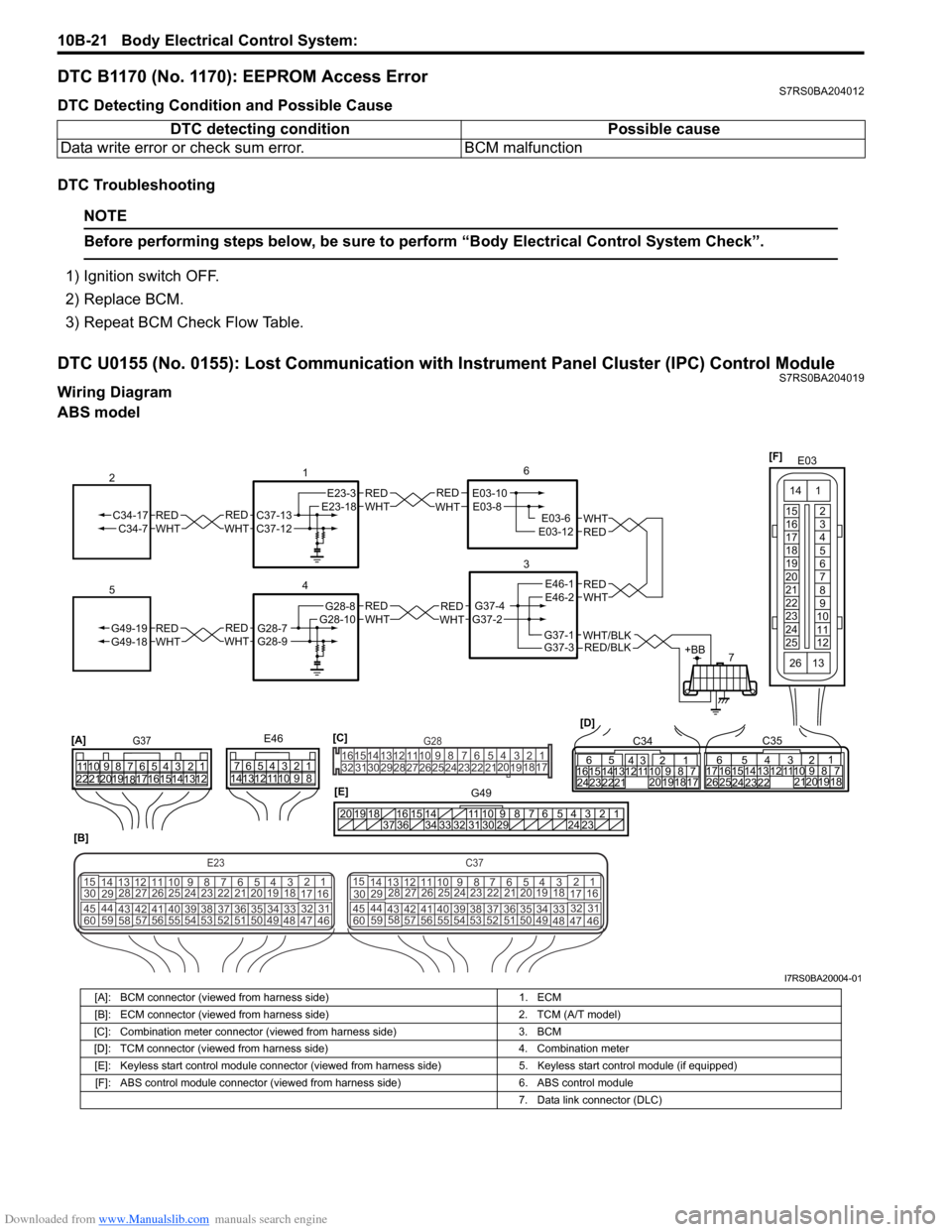
DTC U0155 (No. 0155): Lost Communication with Instrument Panel Cluster (IPC) Control ModuleS7RS0BA204019
Wiring Diagram
ABS model DTC detecting condition Possible cause
Data write error or check sum error. BCM malfunction
REDWHTE03-6E03-12
6
3
7
REDWHT
1
[B]
[A]
G37E46
1234567
1234567
8910
11
8910
11
121314 121314
151617
18
19202122 [D]65
1615 141312 11 43
2423 2122 10 9 8 7
21
1920 1817
C3417 16
26 2515 14
65 3
42
13 12
23 2224 1110 9
212019 87
18
1
C35
[E]
REDWHTC37-13C37-12REDWHTC34-17C34-7
2
12345678910
11
141516
36 34 33 32 31 30 29 24 23
37
181920
[C] [F]
G49
E23-3E23-18
4
REDWHTG28-7G28-9REDWHTG49-19G49-18
5
REDWHTE03-10E03-8
G37-4G37-2
REDWHTE46-1E46-2REDWHTREDWHTG28-8G28-10
E03
15
16
17
18
19
20
21
22
23
24
25 2
3
4
5
6
7
8
9
10
11
12
1
13
14
26
E23C37
34
1819
567
1011
17
20
47 46
495051
2122
52 16
25 9
24
14
29
5557 54 53
59
60 58 2
262728
15
30
56 4832 31
34353637
4042 39 38
44
45 43 41 33 1
1213
238
34
1819
567
1011
17
20
47 46
495051
2122
52 16
25 9
24
14
29
5557 54 53
59
60 58 2
262728
15
30
56 4832 31
34353637
4042 39 38
44
45 43 41 331
1213
238
G281234567
8
910111213141516
1718
19
20
212223242526272829303132
RED/BLKWHT/BLKG37-3G37-1+BB
I7RS0BA20004-01
[A]: BCM connector (viewed from harness side) 1. ECM
[B]: ECM connector (viewed from harness side) 2. TCM (A/T model)
[C]: Combination meter connector (viewed from harness side) 3. BCM
[D]: TCM connector (viewed from harness side) 4. Combination meter
[E]: Keyless start control module connector (viewed from harness side) 5. Keyless start control module (if equipped)
[F]: ABS control module connector (viewed from harness side) 6. ABS control module
7. Data link connector (DLC)
Page 1487 of 1496
Downloaded from www.Manualslib.com manuals search engine Keyless Start System: 10E-25
DTC No. 31: Lost Communication with BCMS7RS0BA504020
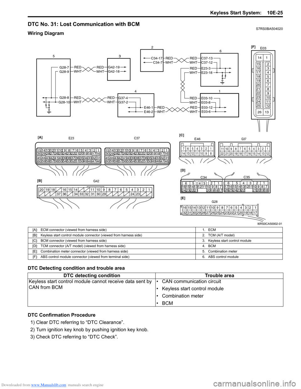
Wiring Diagram
DTC Detecting condition and trouble area
DTC Confirmation Procedure1) Clear DTC referring to “DTC Clearance”.
2) Turn ignition key knob by pushing ignition key knob.
3) Check DTC referring to “DTC Check”.
REDWHTE03-12E03-6
REDWHTE03-10E03-8
REDWHTREDWHTG42-19G42-18 3REDWHTREDWHT
REDWHTREDWHT
REDWHTE46-1
G37-4
G42-19G42-18
G28-8G28-10G37-2
C34-7
E46-2
C34-17
1
2
4
53
21
[A]
E23
G42 C37
34
1819
5671011
17
20
47 46
495051
2122
52 16
25 9
24
14
29
5557 54 53
59
60 58 2
262728
15
30
56 4832 31343536374042 39 38
44
45 43 41 331
1213
238
34
1819
5671011
17
20
47 46
495051
2122
52 16
25 9
24
14
29
5557 54 53
59
60 5826
27
28
15
30
56 4832 31343536374042 39 38
44
45 43 41 33
1213
238
[B] [D]
[C]
65
16 15141312 11 43
24 23 2122 10 9 8 7
21
1920 18 17
C34
17 16
26 25 15 14
65 3
42
13 12
23 2224 1110 9
212019 87
18
1
C35
[E]G28
12345678910111213141516
17181920212223242526272829303132
124
53
67
891011
1213141516171819202122
G37
E46
124
53
67
891011121314
1234567891011
141516
36 34 33 32 31 30 29 24 23
37
181920
G28-9G28-7REDWHTE23-3E23-18
REDWHTC37-13C37-12 6
[F]
E03
15
16
17
18
19
20
21
22
23
24
25 2
3
4
5
6
7
8
9
10
11
12
1
13
14
26
I6RS0CA50002-01
[A]: ECM connector (viewed from harness side)
1. ECM
[B]: Keyless start control module connector (v iewed from harness side) 2. TCM (A/T model)
[C]: BCM connector (viewed from harness side) 3. Keyless start control module
[D]: TCM connector (A/T model) (viewed from harness side) 4. BCM
[E]: Combination meter connector (viewed from harness side) 5. Combination meter
[F]: ABS control module connector (viewed from terminal side) 6. ABS control module
DTC detecting conditionTrouble area
Keyless start control module cannot receive data sent by
CAN from BCM • CAN communication circuit
• Keyless start control module
• Combination meter
•BCM