2005 SUZUKI SWIFT antenna
[x] Cancel search: antennaPage 12 of 1496
Downloaded from www.Manualslib.com manuals search engine 00-7 Precautions:
Warning for Wheel (with tire) RemovalS7RS0B0000003
WARNING!
When removing any of these wheels installed
with wheel bolts, never remove all wheel
bolts at the same time. Leave at least 1 bolt
for each wheel as it is to prevent wheel from
dropping. When removing this remaining 1
bolt, hold wheel and tire so as not to allow
them to come off.
Warning for Handling Emergency Flat Tire
Repair Kit
S7RS0B0000004
WARNING!
If vehicle is equipped with Emergency Flat
Tire Repair Kit instead of spare tire, be sure
to observe “Precaution for Emergency Flat
Tire Repair Kit in Section 2D” when handling
Emergency Flat Tire Repair Kit and repairing
flat tire.
Otherwise, your health may be ruined or it
will be impossible to repair flat tire.
Precautions for Catalytic ConverterS7RS0B0000005
For vehicles equipped with a catalytic converter, use
only unleaded gasoline and be careful not to let a large
amount of unburned gasoline enter the converter or it
can be damaged.
• Conduct a spark jump test only when necessary, make it as short as possible, and do not open the
throttle.
• Conduct engine compression checks within the shortest possible time.
• Avoid situations which can result in engine misfire (e.g. starting the engine when the fuel tank is nearly
empty.)
Precautions for Installing Mobile
Communication Equipment
S7RS0B0000006
When installing mobile communication equipment such
as CB (Citizens-Band)-radi o or cellular-telephone, be
sure to observe the following precautions.
Failure to follow cautions may adversely affect electronic
control system.
• Keep the antenna as far away as possible from the vehicle’s electronic control unit.
• Keep the antenna feeder more than 20 cm (7.9 in.) away from electronic control unit and its wire
harnesses.
• Do not run the antenna feeder parallel with other wire harnesses.
• Confirm that the antenna and feeder are correctly adjusted.
Precaution for CAN Communication SystemS7RS0B0000007
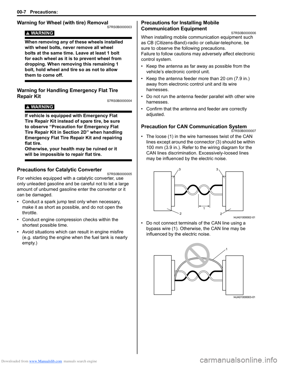
• The loose (1) in the wire harnesses twist of the CAN lines except around the connector (3) should be within
100 mm (3.9 in.). Refer to the wiring diagram for the
CAN lines discrimination. Excessively-loosed lines
may be influenced by the electric noise.
• Do not connect terminals of the CAN line using a bypass wire (1). Otherwise, the CAN line may be
influenced by the electric noise.
33
2
2
1
I4JA01000002-01
1
I4JA01000003-01
Page 63 of 1496
Downloaded from www.Manualslib.com manuals search engine Engine General Information and Diagnosis: 1A-13
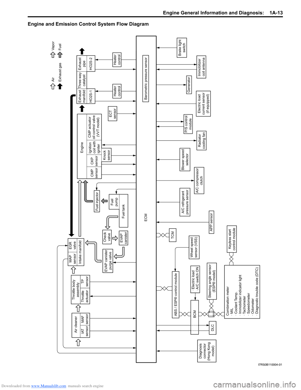
Engine and Emission Control System Flow Diagram
Intake manifold
Exhaust gas AirFuel
Va p o r
EVAP canister purge valve
ECM
Barometric pressure sensor
A/C compressor clutch
Generator
Immobilizer
coil antenna
P/S controlmodule
Brake light switch
Air cleaner
IAT
sensor MAF
sensor
A/C refrigerant
pressure sensor
TP
sensor
Throttle body
assembly
Throttle
actuator
Wheel speed
sensor (VSS)
Steering angle sensor (ESP® model)
ABS / ESP® control module
Blower speed
selector
MAP
sensor EGR
valve
Check valve
EVAP
canisterTCM
Exhaust
manifold Exhaust
pipe
Fuel injector
ECT
sensor
Heater
control
HO2S-1 HO2S-2
Engine
CMP
sensor CKP
sensor
Knock
sensor Ignition
coil with
igniter
Fuel tank
Fuel
pump CMP actuator
oil control valve (VVT model) Three way
catalyst
Heater
control
Radiator
cooling fan
Combination meter
· MIL
· Coolant Temp.
· Immobilizer indicator light
· Tachometer
· Speedometer
· Odometer
· Diagnostic trouble code (DTC)
Keyless start
control module
DLC
· Electric load
· A/C switch ON
BCM
Diagnosis
connector
(Hong Kong model) Electric load
current sensor (if equipped)
APP sensor
I7RS0B110004-01
Page 65 of 1496
![SUZUKI SWIFT 2005 2.G Service Workshop Manual Downloaded from www.Manualslib.com manuals search engine Engine General Information and Diagnosis: 1A-15
Terminal Arrangement of ECM Coupler (Viewed from Harness Side)
[A]: Manual A/C model24. ABS / SUZUKI SWIFT 2005 2.G Service Workshop Manual Downloaded from www.Manualslib.com manuals search engine Engine General Information and Diagnosis: 1A-15
Terminal Arrangement of ECM Coupler (Viewed from Harness Side)
[A]: Manual A/C model24. ABS /](/manual-img/20/7607/w960_7607-64.png)
Downloaded from www.Manualslib.com manuals search engine Engine General Information and Diagnosis: 1A-15
Terminal Arrangement of ECM Coupler (Viewed from Harness Side)
[A]: Manual A/C model24. ABS / ESP® control module 49. Radiator cooling fan motor
[B]: Auto A/C model 25. TCM 50. “RDTR FAN” fuse
1. ECM 26. To other control module connected CAN 51. A/C compressor relay
2. APP sensor assembly 27. Generator 52. Magnet clutch of compressor (A/C model)
3. Shield wire 28. Electric load current sensor (if equipped) 53. “A/C CPRSR” fuse
4. CMP sensor 29. Brake light 54. Ignition coil assembly (for No.1 and No.4 spark
plugs)
5. CKP sensor 30. Brake light switch 55. Ignition coil assembly (for No.2 and No.3 spark
plugs)
6. MAF and IAT sensor 31. Diagnosis connector (Hong Kong model) 56. P/S control module
7. MAP sensor 32. Throttle actuator control relay 57. “RADIO” fuse
8. ECT sensor 33. “THR MOT” fuse 58. Main relay
9. A/C refrigerant pressure sensor 34. Throttle throttle body assembly 59. “IG COIL” fuse
10. A/C evaporator outlet air temp. sensor (Manual A/C model) 35. Throttle actuator
60. Ignition switch
11. HO2S-1 36. TP sensor 61. “IG ACC” fuse
12. HO2S-2 37. Injector No.1 62. “FI” fuse
13. Knock sensor 38. Injector No.2 63. Starting motor control relay
14. Blower motor relay 39. Injector No.3 64. “ST SIG” fuse
15. Blower motor 40. Injector No.4 65. “ST MOT” fuse
16. Blower motor resistor 41. EVAP canister purge valve66. Transmission range switch (A/T model) or CPP
switch (Hong Kong model with M/T)
17. Blower speed selector 42. EGR valve 67. Starting motor
18. A/C switch 43. Oil control valve (Camshaft position
control) (VVT model) 68. Immobilizer coil antenna
19. Blower motor controller 44. Fuel pump relay 69. Main fuse box
20. HVAC control module 45. Fuel pump 70. Battery
21. Data link connector (DLC) 46. Radiator cooling fan motor relay No.1 71. Barometric pressure sensor
22. To other control module connected with DLC 47. Radiator cooling fan motor relay No.2
72. Engine ground
23. BCM 48. Radiator cooling fan motor relay No.3 73. Body ground
E23 C37
34
1819
567
1011
17
20
47 46
495051
2122
52 16
25 9
24
14
29
55
57 54 53
59
60 58 2
262728
15
30
56 4832 31
34353637
40
42 39 38
44
45 43 41 331
1213
238
34
1819
567
1011
17
20
47 46
495051
2122
52 16
25 9
24
14
29
55
57 54 53
59
60 58 2
262728
15
30
56 4832 31
34353637
40
42 39 38
44
45 43 41 331
1213
238
I4RS0A110008-01
Page 67 of 1496

Downloaded from www.Manualslib.com manuals search engine Engine General Information and Diagnosis: 1A-17
Connector: E23Terminal Wire color Circuit Terminal Wire color Circuit 1 BLK/RED Main power supply 31 BLK Ground for ECM
2WHT/RED Power source for ECM internal
memory 32 RED/YELPower supply of throttle
actuator drive circuit
3RED CAN communication line
(active high signal) for ABS/
ESP®
control module, BCM,
combination meter 33 — —
4BRN Engine revolution signal output
for P/S control module 34 REDOutput of 5 V power source for
APP sensor (sub)
5 PPL/WHT 12 V serial communication line
of DLC 35 BRNOutput of 5 V power source for
APP sensor (main)
6 — — 36 YEL APP sensor (sub) signal
7 — — 37 GRN APP sensor (main) signal
8— — 38— —
9— — 39— —
10——40—— 11——41——
12 BLU Diagnosis switch terminal
(Hong Kong model) 42 — —
13 YEL/RED Clock signal for immobilizer
coil antenna 43 — —
14——44——
15 GRN/WHT Fuel pump relay output 45 BLU/ORN Throttle actuator control relay
output
16 BLK/RED Main power supply 46 LT GRN Radiator cooling fan relay No.1
output
17 — — 47 GRY A/C compressor relay output
18 WHT CAN communication line
(active low signal) for ABS/
ESP®
control module BCM,
combination meter 48 GRN
Radiator cooling fan relay No.2
and No.3 output
19 BLU/WHT Electric load signal for heater
blower motor 49 — —
20 GRN/WHT Brake light switch signal 50 — Ground for shield wire of APP
sensor
21 — — 51 WHT Ground for APP sensor (sub)
22 — — 52 BLU Ground for APP sensor (main)
23——53——
24 — — 54 ORN Ground for sensors
25 PPL Vehicle speed signal output for
P/S control module 55 REDA/C refrigerant pressure
sensor signal
26 RED/BLU EPS signal 56 — —
27 — — 57 WHT/BLK A/C evaporator outlet air temp.
sensor signal (Manual A/C
model)
28 YEL/BLK Serial communication line for
immobilizer coil antenna 58 — —
29 BLK/WHT Ignition switch signal 59 — —
30 WHT Starting motor control relay
output 60 BRN/WHT Main power supply relay output
Page 70 of 1496
Downloaded from www.Manualslib.com manuals search engine 1A-20 Engine General Information and Diagnosis:
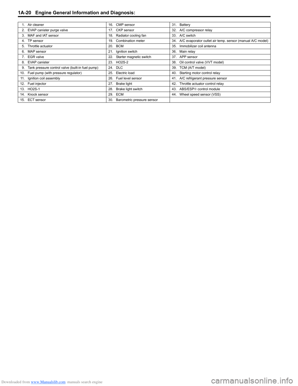
1. Air cleaner16. CMP sensor31. Battery
2. EVAP canister purge valve 17. CKP sensor32. A/C compressor relay
3. MAF and IAT sensor 18. Radiator cooling fan33. A/C switch
4. TP sensor 19. Combination meter34. A/C evaporator outlet air temp. sensor (manual A/C model)
5. Throttle actuator 20. BCM35.Immobilizer coil antenna
6. MAP sensor 21. Ignition switch36. Main relay
7. EGR valve 22. Starter magnetic switch37. APP sensor
8. EVAP canister 23. HO2S-238. Oil control valve (VVT model)
9. Tank pressure control valve (built-in fuel pump) 24. DLC 39. TCM (A/T model)
10. Fuel pump (with pressure regulator) 25. Electric load40. Starting motor control relay
11. Ignition coil assembly 26. Fuel level sensor41. A/C refrigerant pressure sensor
12. Fuel injector 27. Brake light42. Throttle actuator control relay
13. HO2S-1 28. Brake light switch43. ABS/ESP® control module
14. Knock sensor 29. ECM44. Wheel speed sensor (VSS)
15. ECT sensor 30. Barometric pressure sensor
Page 71 of 1496
Downloaded from www.Manualslib.com manuals search engine Engine General Information and Diagnosis: 1A-21
Component Location
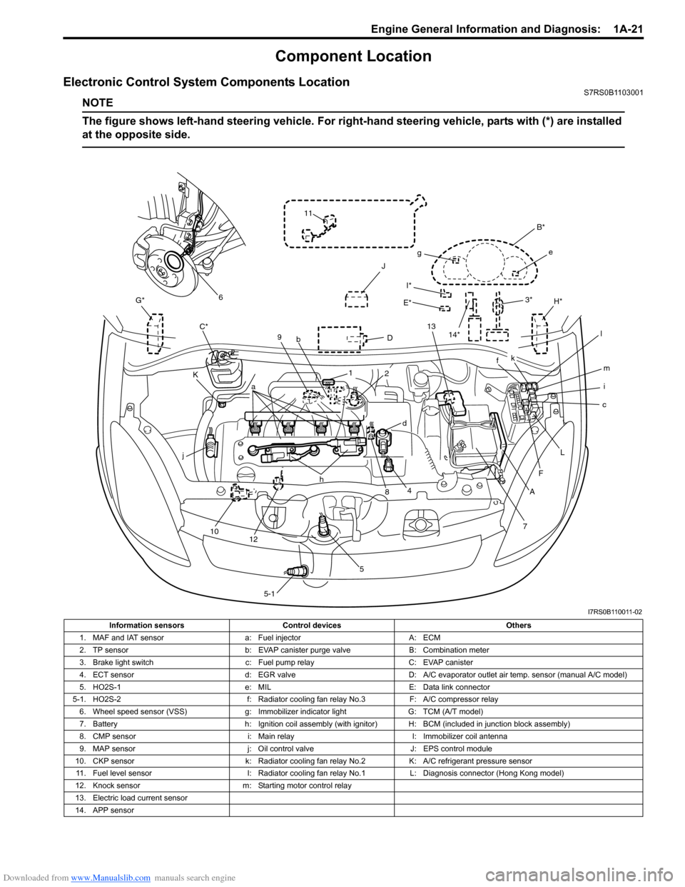
Electronic Control System Components LocationS7RS0B1103001
NOTE
The figure shows left-hand steering vehicle. For right-hand steering vehicle, parts with (*) are installed
at the opposite side.
I*
E*
G*
D
K H*
J
C*
7
A
F
c
L
i m
f
B*
e
g
k
l
13
3*
4
j
10 12 h
58
a
9
b
1
5-1
d
2
11
6
14*
I7RS0B110011-02
Information sensors Control devices Others
1. MAF and IAT sensor a: Fuel injectorA: ECM
2. TP sensor b: EVAP canister purge valve B: Combination meter
3. Brake light switch c: Fuel pump relayC: EVAP canister
4. ECT sensor d: EGR valveD: A/C evaporator outlet air temp. sensor (manual A/C model)
5. HO2S-1 e: MILE: Data link connector
5-1. HO2S-2 f: Radiator cooling fan relay No.3F: A/C compressor relay
6. Wheel speed sensor (VSS) g: Immobilizer indicator lightG: TCM (A/T model)
7. Battery h: Ignition coil assembly (with ignitor) H: BCM (included in junction block assembly)
8. CMP sensor i: Main relayI: Immobilizer coil antenna
9. MAP sensor j: Oil control valveJ: EPS control module
10. CKP sensor k: Radiator cooling fan relay No.2K: A/C refrigerant pressure sensor
11. Fuel level sensor l: Radiator cooling fan relay No.1L: Diagnosis connector (Hong Kong model)
12. Knock sensor m: Starting motor control relay
13. Electric load current sensor
14. APP sensor
Page 81 of 1496
Downloaded from www.Manualslib.com manuals search engine Engine General Information and Diagnosis: 1A-31
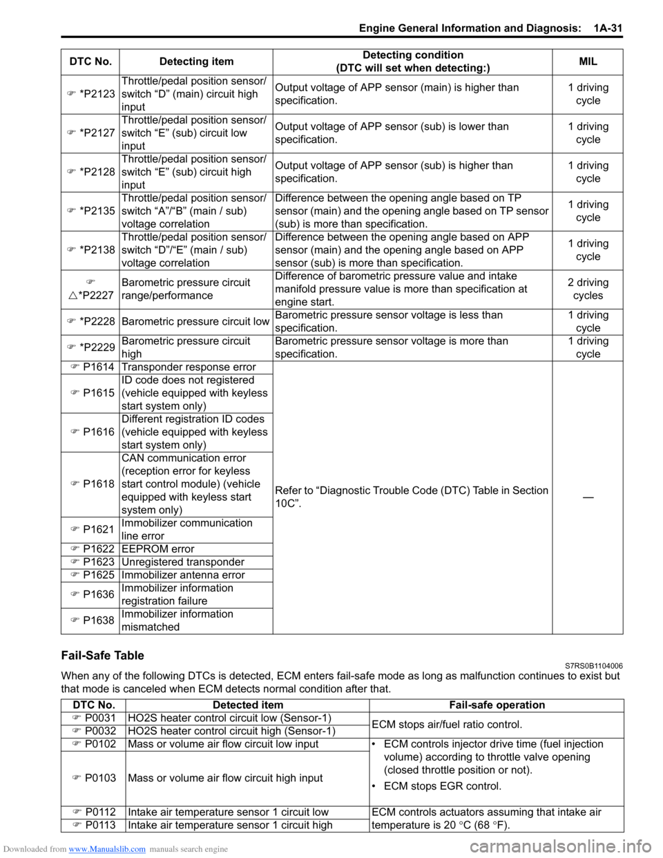
Fail-Safe TableS7RS0B1104006
When any of the following DTCs is detected, ECM enters fail-safe mode as long as malfunction continues to exist but
that mode is canceled when ECM de tects normal condition after that.
�)
*P2123 Throttle/pedal position sensor/
switch “D” (main) circuit high
input Output voltage of APP sensor (main) is higher than
specification.
1 driving
cycle
�) *P2127 Throttle/pedal position sensor/
switch “E” (sub) circuit low
input Output voltage of APP sens
or (sub) is lower than
specification. 1 driving
cycle
�) *P2128 Throttle/pedal position sensor/
switch “E” (sub) circuit high
input Output voltage of APP sensor (sub) is higher than
specification.
1 driving
cycle
�) *P2135 Throttle/pedal position sensor/
switch “A”/“B” (main / sub)
voltage correlation Difference between the opening angle based on TP
sensor (main) and the opening angle based on TP sensor
(sub) is more than specification.
1 driving
cycle
�) *P2138 Throttle/pedal position sensor/
switch “D”/“E” (main / sub)
voltage correlation Difference between the opening angle based on APP
sensor (main) and the opening angle based on APP
sensor (sub) is more
than specification. 1 driving
cycle
�)
�U *P2227 Barometric pressure circuit
range/performance Difference of barometric pressure value and intake
manifold pressure value is
more than specification at
engine start. 2 driving
cycles
�) *P2228 Barometric pressure circuit low Barometric pressure sens
or voltage is less than
specification. 1 driving
cycle
�) *P2229 Barometric pressure circuit
high Barometric pressure sensor voltage is more than
specification. 1 driving
cycle
�) P1614 Transponder response error
Refer to “Diagnostic Trouble Code (DTC) Table in Section
10C”. —
�) P1615 ID code does not registered
(vehicle equipped with keyless
start system only)
�) P1616 Different registration ID codes
(vehicle equipped with keyless
start system only)
�) P1618 CAN communication error
(reception error for keyless
start control module) (vehicle
equipped with keyless start
system only)
�) P1621 Immobilizer communication
line error
�) P1622
EEPROM error
�) P1623 Unregistered transponder
�) P1625 Immobilizer antenna error
�) P1636 Immobilizer information
registration failure
�) P1638 Immobilizer information
mismatched
DTC No. Detecting item
Detecting condition
(DTC will set when detecting:) MIL
DTC No.
Detected item Fail-safe operation
�) P0031 HO2S heater control circuit low (Sensor-1)
ECM stops air/fuel ratio control.
�) P0032 HO2S heater control circuit high (Sensor-1)
�) P0102 Mass or volume air flow circuit low input • ECM controls injector drive time (fuel injection
volume) according to throttle valve opening
(closed throttle position or not).
• ECM stops EGR control.
�)
P0103 Mass or volume air flow circuit high input
�) P0112 Intake air temperature sensor 1 circuit low ECM controls actuators assuming that intake air
temperature is 20 °C (68 ° F).
�) P0113 Intake air temperature sensor 1 circuit high
Page 231 of 1496
Downloaded from www.Manualslib.com manuals search engine Engine General Information and Diagnosis: 1A-181
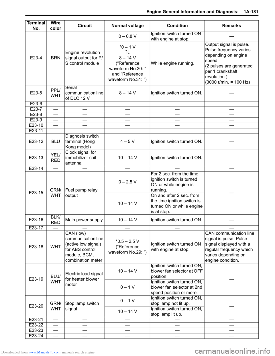
E23-4 BRNEngine revolution
signal output for P/
S control module 0 – 0.8 V
Ignition switch turned ON
with engine at stop. —
*0 – 1 V ↑↓
8 – 14 V
(“Reference
waveform No.30: ” and “Reference
waveform No.31: ”) While engine running. Output signal is pulse.
Pulse frequency varies
depending on engine
speed.
(2 pulses are generated
per 1 crankshaft
revolution.)
(3000 r/min. = 100 Hz)
E23-5 PPL/
WHT Serial
communication line
of DLC 12 V
8 – 14 V Ignition switch turned ON. —
E23-6 — — — — —
E23-7 — — — — —
E23-8 — — — — —
E23-9 — — — — —
E23-10 — — — — — E23-11 — — — — —
E23-12 BLU Diagnosis switch
terminal (Hong
Kong model) 4 – 5 V Ignition switch turned ON. —
E23-13 YEL/
RED Clock signal for
immobilizer coil
antenna
10 – 14 V Ignition switch turned ON. —
E23-14 — — — — —
E23-15 GRN/
WHT Fuel pump relay
output 0 – 2.5 V
For 2 sec. from the time
ignition switch is turned
ON or while engine is
running.
—
10 – 14 V On and after 2 sec. from
the time ignition switch is
turned ON or while engine
is at stop.
E23-16 BLK/
RED Main power supply 10 – 14 V Ignition switch turned ON. —
E23-17 — — — — —
E23-18 WHT CAN (low)
communication line
(active low signal)
for ABS control
module, BCM,
combination meter *0.5 – 2.5 V
(“Reference
waveform No.29: ”) Ignition switch turned ON
with engine at stop. CAN communication line
signal is pulse. Pulse
signal displayed with a
regular frequency which
varies depending on
engine condition.
E23-19 BLU/
WHT Electric load signal
for heater blower
motor 10 – 14 V
Ignition switch turned ON,
blower fan selector at OFF
position.
—
0 – 1 V Ignition switch turned ON,
blower fan selector at 2nd
speed position or more.
E23-20 GRN/
WHT Stop lamp switch
signal 0 – 1 V
Ignition switch turned ON,
stop lamp not lit up.
—
10 – 14 V Ignition switch turned ON,
stop lamp lit up.
E23-21 — — — — —
E23-22 — — — — —
E23-23 — — — — —
E23-24 — — — — —
Terminal
No. Wire
color Circuit Normal voltage Condition Remarks