2005 SUZUKI SWIFT antenna
[x] Cancel search: antennaPage 1272 of 1496
Downloaded from www.Manualslib.com manuals search engine 9A-101 Wiring Systems:
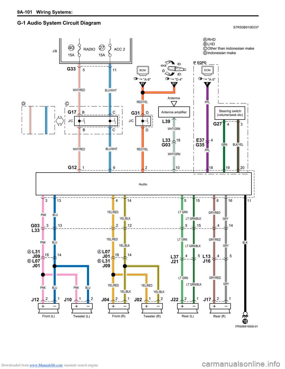
G-1 Audio System Circuit DiagramS7RS0B910E037
PPL
PPL
G335
GRY
18141814L37J21
G03 L333 13 2
515 14
4 5
4
5
11
21 1
2 2
1 1
2 2
1 2
1
3
13 4
14 5
15 6
16 11
RY"D-4"RY
WHT/RED
G121
J/C
G17
WHT/RED
J/B15ARADIO
40
RED/YEL
J/C
G31
BCM
"A-8"
Antenna amplifier
WHT/GRN
L39
L33
G0318E37
G354
WHT/GRN
BLU/WHT
BLU/WHT
15A ACC 2
27
BLK
10
Tweeter (L)Front (L)
PNKBLU
J12
J10
Tweeter (R)Front (R)
J04J02
YEL/BLK
YEL/RED
Rear (R)Rear (L)
LT GRN
LT GRN/BLKPNKBLUPNKBLUYEL/BLK
YEL/RED
YEL/BLK
YEL/REDLT GRN
LT GRN/BLK
GRY/RED
GRY
GRY/RED
PNKBLUYEL/BLK
YEL/REDLT GRN
LT GRN/BLKGRY
GRY/RED
12
Audio
RED/YEL
921 0
J22J17
B
B C
C D
DSteering switch
(volume/seek etc)
G27
GRN
1920
BLK/YEL
4 3
L13
J16
4
P
ECM
"A-5"
18
RHD
LHD
Other than indonesian make
Indonesian make
ABC
DC
D
Antenna
L31
J09
L07 J01A
B
L07 J01
L31 J09A
B
IF EQPD
I7RS0B910938-01
Page 1301 of 1496
Downloaded from www.Manualslib.com manuals search engine Instrumentation / Driver Info. / Horn: 9C-6
Component Location
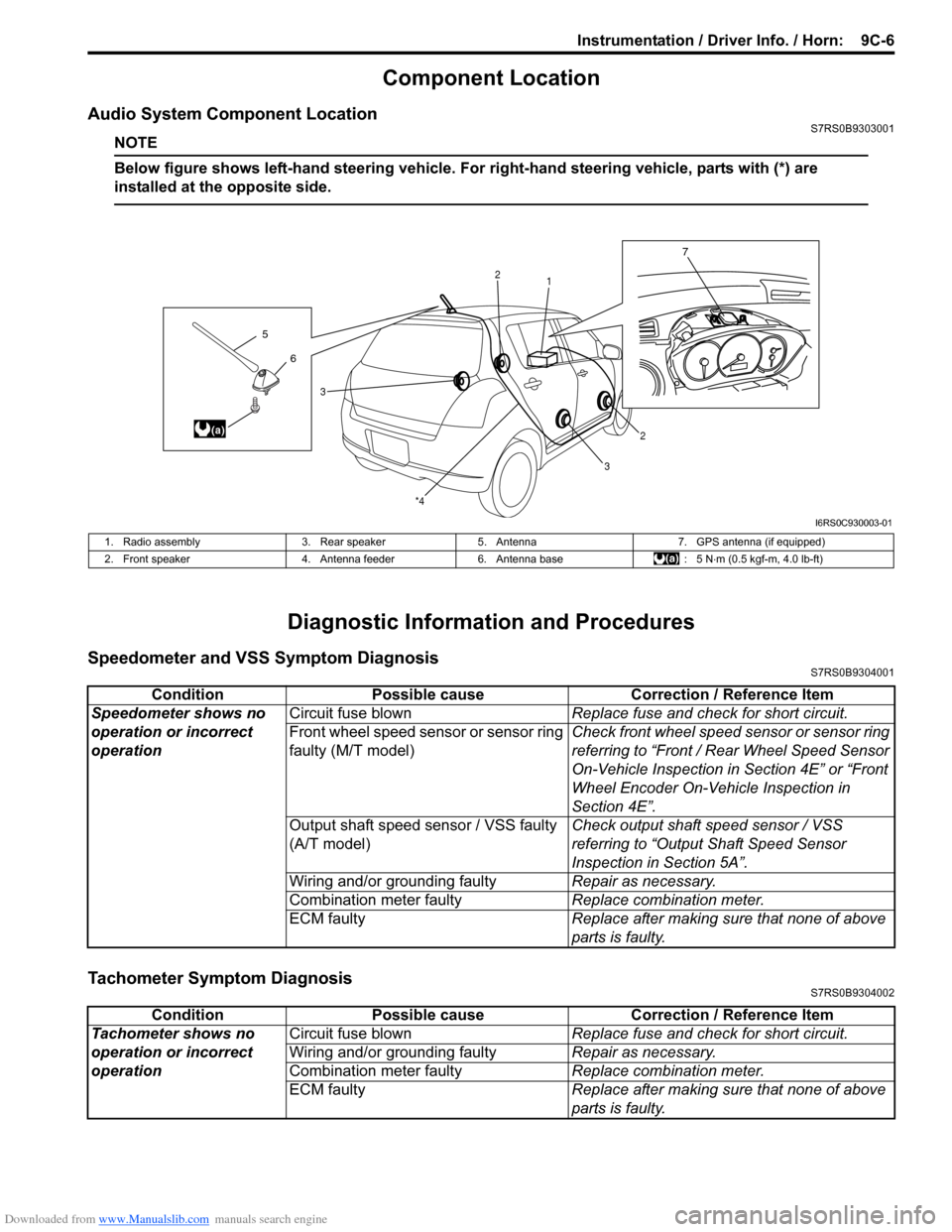
Audio System Component LocationS7RS0B9303001
NOTE
Below figure shows left-hand steering vehicle. For right-hand steering vehicle, parts with (*) are
installed at the opposite side.
Diagnostic Information and Procedures
Speedometer and VSS Symptom DiagnosisS7RS0B9304001
Tachometer Symptom DiagnosisS7RS0B9304002
6
5
(a)
7
1
2
2
3
3
*4
I6RS0C930003-01
1. Radio assembly
3. Rear speaker5. Antenna 7. GPS antenna (if equipped)
2. Front speaker 4. Antenna feeder6. Antenna base : 5 N⋅m (0.5 kgf-m, 4.0 lb-ft)
Condition Possible cause Correction / Reference Item
Speedometer shows no
operation or incorrect
operation Circuit fuse blown
Replace fuse and check for short circuit.
Front wheel speed sensor or sensor ring
faulty (M/T model) Check front wheel speed sensor or sensor ring
referring to “Front / Rear Wheel Speed Sensor
On-Vehicle Inspection in
Section 4E” or “Front
Wheel Encoder On-Vehicle Inspection in
Section 4E”.
Output shaft speed sensor / VSS faulty
(A/T model) Check output shaft
speed sensor / VSS
referring to “Output Shaft Speed Sensor
Inspection in Section 5A”.
Wiring and/or grounding faulty Repair as necessary.
Combination meter faulty Replace combination meter.
ECM faulty Replace after making sure that none of above
parts is faulty.
ConditionPossible cause Correction / Reference Item
Tachometer shows no
operation or incorrect
operation Circuit fuse blown
Replace fuse and check for short circuit.
Wiring and/or grounding faulty Repair as necessary.
Combination meter faulty Replace combination meter.
ECM faulty Replace after making sure that none of above
parts is faulty.
Page 1307 of 1496
Downloaded from www.Manualslib.com manuals search engine Instrumentation / Driver Info. / Horn: 9C-12
Clock Symptom Diagnosis (If Equipped)S7RS0B9304016
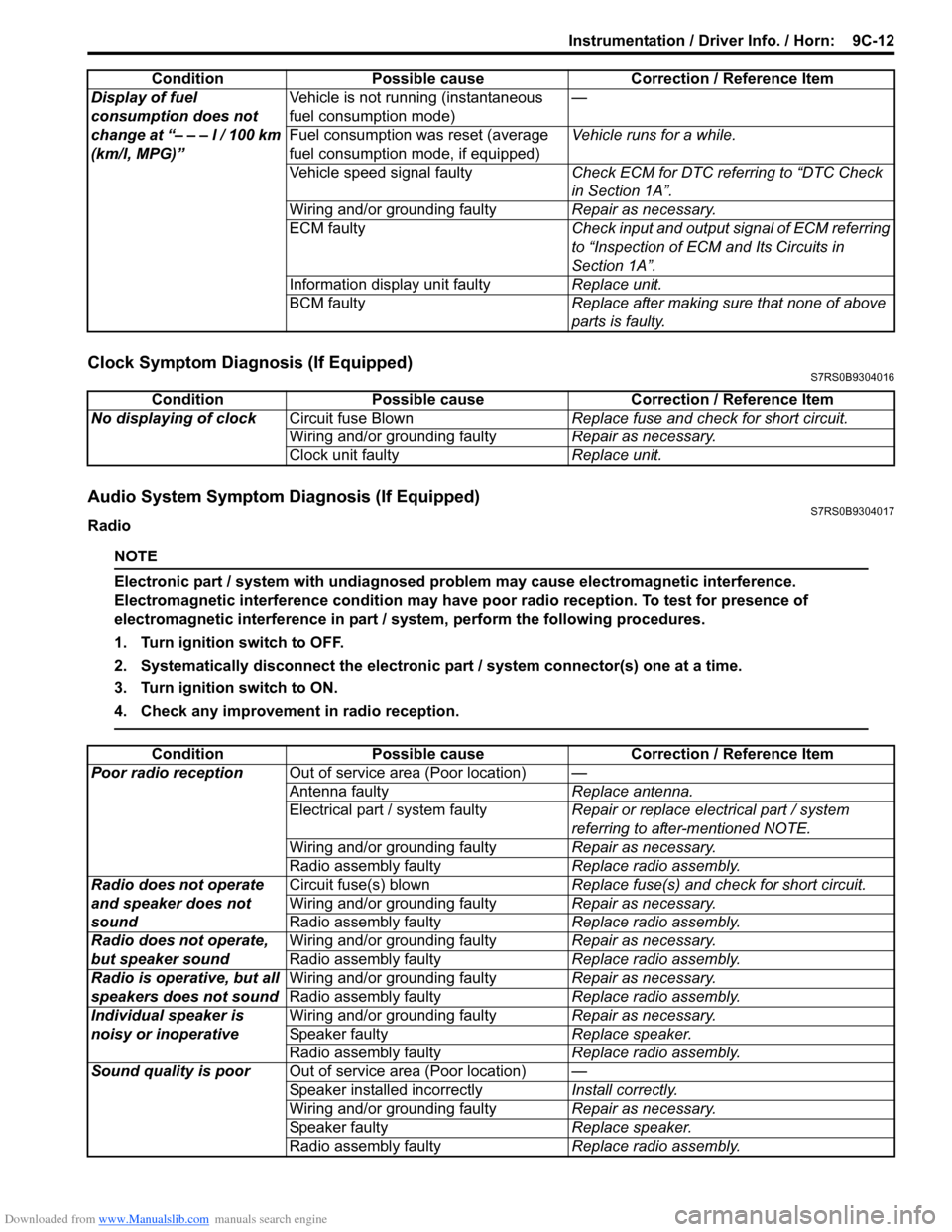
Audio System Symptom Diagnosis (If Equipped)S7RS0B9304017
Radio
NOTE
Electronic part / system with undiagnosed pr oblem may cause electromagnetic interference.
Electromagnetic interference condition may have poor radio reception. To test for presence of
electromagnetic interference in part / system, perform the following procedures.
1. Turn ignition switch to OFF.
2. Systematically disconnect the electronic part / system connector(s) one at a time.
3. Turn ignition switch to ON.
4. Check any improvement in radio reception.
Display of fuel
consumption does not
change at “– – – l / 100 km
(km/l, MPG)” Vehicle is not running (instantaneous
fuel consumption mode)
—
Fuel consumption was reset (average
fuel consumption mo de, if equipped)Vehicle runs for a while.
Vehicle speed signal faulty Check ECM for DTC referring to “DTC Check
in Section 1A”.
Wiring and/or grounding faulty Repair as necessary.
ECM faulty Check input and output signal of ECM referring
to “Inspection of ECM and Its Circuits in
Section 1A”.
Information display unit faulty Replace unit.
BCM faulty Replace after making sure that none of above
parts is faulty.
Condition Possible cause Correction / Reference Item
Condition
Possible cause Correction / Reference Item
No displaying of clock Circuit fuse Blown Replace fuse and check for short circuit.
Wiring and/or grounding faulty Repair as necessary.
Clock unit faulty Replace unit.
ConditionPossible cause Correction / Reference Item
Poor radio reception Out of service area (Poor location) —
Antenna faulty Replace antenna.
Electrical part / system faulty Repair or replace electrical part / system
referring to after-mentioned NOTE.
Wiring and/or grounding faulty Repair as necessary.
Radio assembly faulty Replace radio assembly.
Radio does not operate
and speaker does not
sound Circuit fuse(s) blown
Replace fuse(s) and check for short circuit.
Wiring and/or grounding faulty Repair as necessary.
Radio assembly faulty Replace radio assembly.
Radio does not operate,
but speaker sound Wiring and/or grounding faulty
Repair as necessary.
Radio assembly faulty Replace radio assembly.
Radio is operative, but all
speakers does not sound Wiring and/or grounding faulty
Repair as necessary.
Radio assembly faulty Replace radio assembly.
Individual speaker is
noisy or inoperative Wiring and/or grounding faulty
Repair as necessary.
Speaker faulty Replace speaker.
Radio assembly faulty Replace radio assembly.
Sound quality is poor Out of service area (Poor location) —
Speaker installed incorrectly Install correctly.
Wiring and/or grounding faulty Repair as necessary.
Speaker faulty Replace speaker.
Radio assembly faulty Replace radio assembly.
Page 1313 of 1496
Downloaded from www.Manualslib.com manuals search engine Instrumentation / Driver Info. / Horn: 9C-18
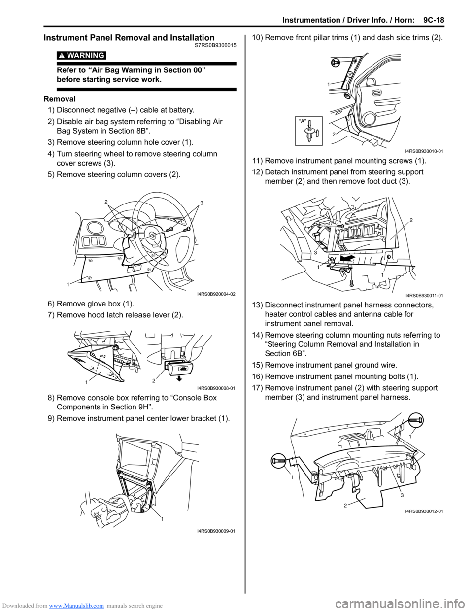
Instrument Panel Removal and InstallationS7RS0B9306015
WARNING!
Refer to “Air Bag Warning in Section 00”
before starting service work.
Removal
1) Disconnect negative (–) cable at battery.
2) Disable air bag system referring to “Disabling Air Bag System in Section 8B”.
3) Remove steering column hole cover (1).
4) Turn steering wheel to remove steering column cover screws (3).
5) Remove steering column covers (2).
6) Remove glove box (1).
7) Remove hood latch release lever (2).
8) Remove console box referring to “Console Box Components in Section 9H”.
9) Remove instrument panel center lower bracket (1). 10) Remove front pillar trims
(1) and dash side trims (2).
11) Remove instrument panel mounting screws (1).
12) Detach instrument panel from steering support member (2) and then remove foot duct (3).
13) Disconnect instrument panel harness connectors, heater control cables and antenna cable for
instrument panel removal.
14) Remove steering column mounting nuts referring to “Steering Column Remova l and Installation in
Section 6B”.
15) Remove instrument panel ground wire.
16) Remove instrument panel mounting bolts (1).
17) Remove instrument panel (2) with steering support member (3) and instrument panel harness.
1
32
I4RS0B920004-02
2
1I4RS0B930008-01
1
I4RS0B930009-01
“A”
“A”
1
2
I4RS0B930010-01
1
1 2
3
I4RS0B930011-01
1 1
2
3I4RS0B930012-01
Page 1316 of 1496
Downloaded from www.Manualslib.com manuals search engine 9C-21 Instrumentation / Driver Info. / Horn:
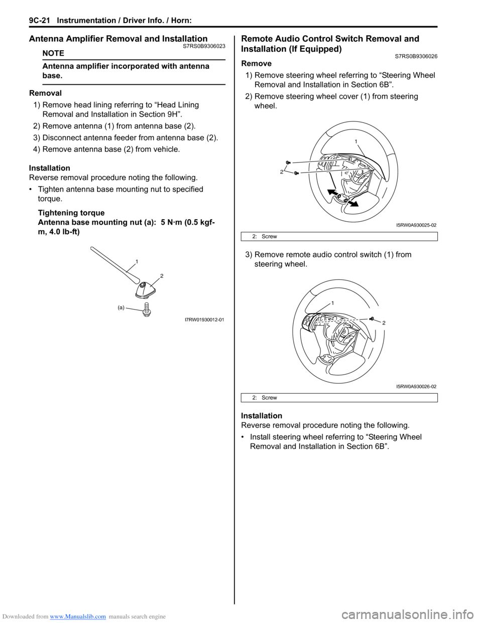
Antenna Amplifier Removal and InstallationS7RS0B9306023
NOTE
Antenna amplifier incorporated with antenna
base.
Removal1) Remove head lining referring to “Head Lining Removal and Installa tion in Section 9H”.
2) Remove antenna (1) from antenna base (2).
3) Disconnect antenna feeder from antenna base (2).
4) Remove antenna base (2) from vehicle.
Installation
Reverse removal procedure noting the following.
• Tighten antenna base mounting nut to specified torque.
Tightening torque
Antenna base mounting nut (a): 5 N·m (0.5 kgf-
m, 4.0 lb-ft)
Remote Audio Control Switch Removal and
Installation (If Equipped)
S7RS0B9306026
Remove
1) Remove steering wheel re ferring to “Steering Wheel
Removal and Installati on in Section 6B”.
2) Remove steering wheel cover (1) from steering wheel.
3) Remove remote audio control switch (1) from steering wheel.
Installation
Reverse removal procedure noting the following.
• Install steering wheel referring to “Steering Wheel Removal and Installati on in Section 6B”.
(a)1
2
I7RW01930012-01
2: Screw
2: Screw
2
1
I5RW0A930025-02
1
2
I5RW0A930026-02
Page 1317 of 1496
Downloaded from www.Manualslib.com manuals search engine Instrumentation / Driver Info. / Horn: 9C-22
Remote Audio Control Switch Inspection (If
Equipped)
S7RS0B9306024
1) Remove driver air bag (inflator) module referring to
“Driver Air Bag (Inflator) Module Removal and
Installation in Section 8B”.
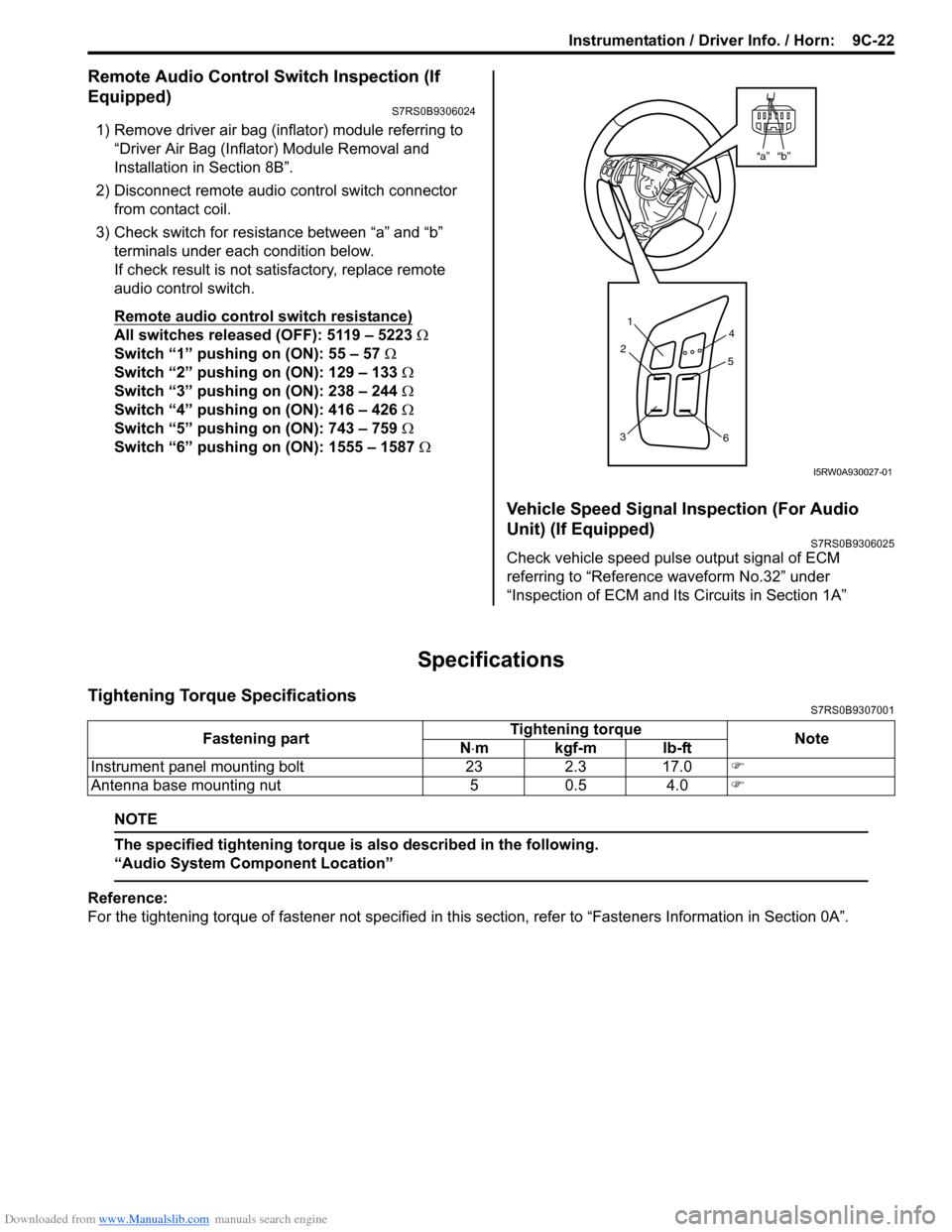
2) Disconnect remote audio control switch connector
from contact coil.
3) Check switch for resistance between “a” and “b” terminals under each condition below.
If check result is not satisfactory, replace remote
audio control switch.
Remote audio control switch resistance)
All switches released (OFF): 5119 – 5223 Ω
Switch “1” pushing on (ON): 55 – 57 Ω
Switch “2” pushing on (ON): 129 – 133 Ω
Switch “3” pushing on (ON): 238 – 244 Ω
Switch “4” pushing on (ON): 416 – 426 Ω
Switch “5” pushing on (ON): 743 – 759 Ω
Switch “6” pushing on (ON): 1555 – 1587 Ω
Vehicle Speed Signal Inspection (For Audio
Unit) (If Equipped)
S7RS0B9306025
Check vehicle speed pulse output signal of ECM
referring to “Reference waveform No.32” under
“Inspection of ECM and Its Circuits in Section 1A”
Specifications
Tightening Torque SpecificationsS7RS0B9307001
NOTE
The specified tightening torque is also described in the following.
“Audio System Component Location”
Reference:
For the tightening torque of fastener not specified in this section, refer to “Fasteners Information in Section 0A”.
“b”“a”
1
2
3 4
5
6
I5RW0A930027-01
Fastening part Tightening torque
Note
N ⋅mkgf-mlb-ft
Instrument panel mounting bolt 23 2.3 17.0 �)
Antenna base mounting nut 5 0.5 4.0 �)
Page 1402 of 1496
Downloaded from www.Manualslib.com manuals search engine 10-ii Table of Contents
DTC P1615: ID Code Does Not Registered (Vehicle equipped with keyless start system
only) ................................................................10C-9
DTC P1616: Different Registration ID Codes (Vehicle equipped with keyless start system
only) ..............................................................10C-10
DTC P1618: CAN Communication Error (Reception Error for Keyless Start Control
Module) (Vehicle equipped with keyless
start system only) ..........................................10C-11
DTC P1621: Immobilizer Communication Line Error ......................................................10C-12
DTC P1622: EEPROM Reading / Writing Error ..............................................................10C-13
DTC P1623: Unregistered Transponder .........10C-13
DTC P1625: Immobilizer An tenna Error..........10C-14
DTC P1636: Immobilizer Information Registration Failure .......................................10C-14
DTC P1638: Immobilizer Information Mismatched ...................................................10C-15
Inspection of Immobilizer Control Module (ICM) and Its Circuit ....... ...............................10C-16
Repair Instructions ........... ...............................10C-18
Immobilizer Control Mo dule (ICM) Removal
and Installation ..............................................10C-18
Registration of the Ignition Key .......................10C-18
Procedure after ECM Replacement ................10C-18
Special Tools and Equipmen t .........................10C-19
Special Tool ....................................................10C-19
Keyless Start System ....... ......................10E-1
General Description ........................................... 10E-1
Keyless Start System Description ..................... 10E-1
Parts and Functions .......................................... 10E-2
Keyless Engine Start Function .......................... 10E-3
Door Lock Function of Keyless Start System .... 10E-4
Operation Area of Remote Controller................ 10E-5
Alarm Function .................................................. 10E-6
CAN Communication System Description......... 10E-6
Schematic and Routing Diagram ...................... 10E-7 Keyless Start System El ectric Wiring Circuit
Diagram .......................................................... 10E-7
Diagnostic Information and Procedures .......... 10E-8 Precautions in Diagnosing Troubles ................. 10E-8
Self-Diagnosis Function .................................... 10E-8
Keyless Start System Diagn osis Introduction ... 10E-8 Keyless Start System Chec
k ............................. 10E-8
Customer Questionnaire (E xample) .................. 10E-9
Key Indicator Lamp Check .............................. 10E-10
DTC Check...................................................... 10E-10
DTC Table ....................................................... 10E-11
DTC Clearance ............................................... 10E-12
Keyless Start System Symp tom Diagnosis ..... 10E-12
Keyless Start System Operation Inspection .... 10E-13
Door Lock Operation (Keyless Start System) . 10E-14
Inspection of Keyless Start Control Module and Its Circuits .............................................. 10E-14
No DTC Detection After Performing DTC Check ............................................................ 10E-18
Key Indicator Lamp Circuit Check (Key indicator lamp doesn’t light when ignition
knob switch is pushed.) ................................. 10E-20
Keyless Start Control Module Power and Ground Circuit Check .................................... 10E-22
DTC No. 11: Communi cation Error with
Steering Lock Unit ......................................... 10E-23
DTC No. 13 / No. 14: Release Signal Error from Steering Lock Unit / Steering Lock Unit
Malfunction .................................................... 10E-24
DTC No. 21 / No. 22: Internal Error of Keyless Start Control Module (EEPROM reading
error) / (EEPROM writing error) ............ ........ 10E-24
DTC No. 31: Lost Commun ication with BCM .. 10E-25
DTC No. 33: Control Module Communication
Bus Off .......................................................... 10E-27
DTC No. 51 / No. 52 / No. 53: Driver Side / Passenger Side / Rear End Door Request
Switch Failure................................................ 10E-28
Repair Instructions ............ .............................. 10E-30
Antennas and Request Switches Removal and Installation .............................................. 10E-30
Front Door (Driver and Passenger Side), Rear End Door Request Switch Inspection............ 10E-31
Steering Lock Unit Removal and Installation .. 10E-31
Steering Lock Unit Inspection ......................... 10E-31
Front Door Lock Switch In spection ................. 10E-31
Keyless Start Control Module Removal and Installation ..................................................... 10E-32
Remote Controller Inspection.......................... 10E-32
Replacement of Remote Controller Battery .... 10E-32
Registration Procedure for Remote Controller
ID Code ......................................................... 10E-33
Page 1445 of 1496
Downloaded from www.Manualslib.com manuals search engine Immobilizer Control System: 10C-2
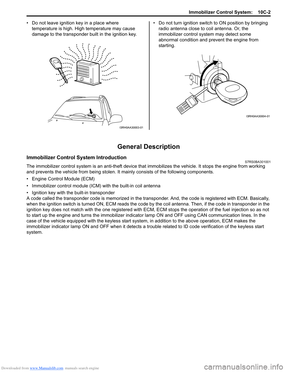
• Do not leave ignition key in a place where
temperature is high. High temperature may cause
damage to the transponder built in the ignition key. • Do not turn ignition switch to ON position by bringing
radio antenna close to coil antenna. Or, the
immobilizer control syst em may detect some
abnormal condition and prevent the engine from
starting.
General Description
Immobilizer Control System IntroductionS7RS0BA301001
The immobilizer control system is an anti-theft device that immobilizes the vehicle. It stops the engine from working
and prevents the vehicle from being stolen. It mainly consists of the following components.
• Engine Control Module (ECM)
• Immobilizer control module (ICM) with the built-in coil antenna
• Ignition key with the built-in transponder
A code called the transponder code is memorized in the tran sponder. And, the code is registered with ECM. Basically,
when the ignition switch is turned ON, ECM reads the code by the coil antenna. Then, if the code in transponder in the
ignition key does not match with the one registered with ECM, ECM stops the operati on of the fuel injection so as not
to start up the engine and turns the immobilizer indi cator lamp ON and OFF using CA N communication lines. In the
case of the vehicle equipped with the keyless start system , in addition to the above operation, ECM makes the
immobilizer indicator lamp ON and OFF when it detects a trouble related to ID code verification of the keyless start
system.
I3RH0AA30003-01
I3RH0AA30004-01