2005 SUZUKI SWIFT Pistons
[x] Cancel search: PistonsPage 331 of 1496
Downloaded from www.Manualslib.com manuals search engine Engine Mechanical: 1D-46
Pistons, Piston Rings, Connecting Rods and
Cylinders Disassembly and Assembly
S7RS0B1406031
Disassembly1) Using piston ring expander, remove two compression rings (Top and 2nd) and oil ring from
piston.
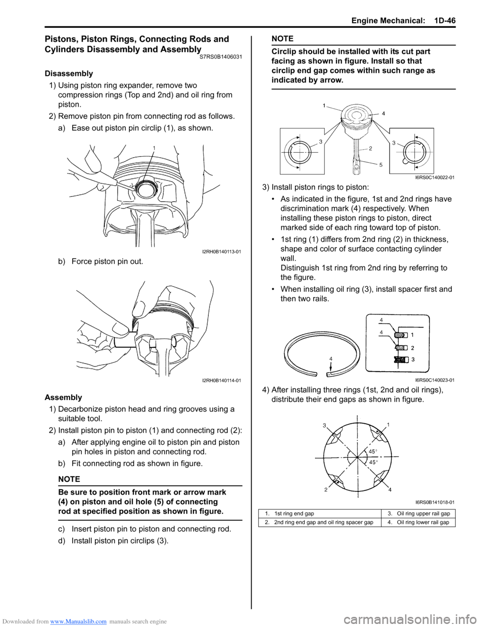
2) Remove piston pin from connecting rod as follows. a) Ease out piston pin circlip (1), as shown.
b) Force piston pin out.
Assembly 1) Decarbonize piston head and ring grooves using a suitable tool.
2) Install piston pin to piston (1) and connecting rod (2): a) After applying engine oil to piston pin and piston pin holes in piston and connecting rod.
b) Fit connecting rod as shown in figure.
NOTE
Be sure to position front mark or arrow mark
(4) on piston and oil hole (5) of connecting
rod at specified position as shown in figure.
c) Insert piston pin to piston and connecting rod.
d) Install piston pin circlips (3).
NOTE
Circlip should be installed with its cut part
facing as shown in figure. Install so that
circlip end gap comes within such range as
indicated by arrow.
3) Install piston rings to piston:
• As indicated in the figure, 1st and 2nd rings have discrimination mark (4) respectively. When
installing these piston rings to piston, direct
marked side of each ring toward top of piston.
• 1st ring (1) differs from 2nd ring (2) in thickness, shape and color of surface contacting cylinder
wall.
Distinguish 1st ring from 2nd ring by referring to
the figure.
• When installing oil ring (3), install spacer first and then two rails.
4) After installing three rings (1st, 2nd and oil rings), distribute their end gaps as shown in figure.
I2RH0B140113-01
I2RH0B140114-01
1. 1st ring end gap 3. Oil ring upper rail gap
2. 2nd ring end gap and oil ring spacer gap 4. Oil ring lower rail gap
I6RS0C140022-01
I6RS0C140023-01
I6RS0B141018-01
Page 332 of 1496
Downloaded from www.Manualslib.com manuals search engine 1D-47 Engine Mechanical:
Cylinders, Pistons and Piston Rings InspectionS7RS0B1406032
Cylinder
Visual inspection
Inspect cylinder walls for scratches, roughness or ridges
which indicate excessive wear. If cylinder bore is very
rough or deeply scratched, or ridged, rebore cylinder and
use over size piston.
Cylinder bore diameter, taper and out-of-round
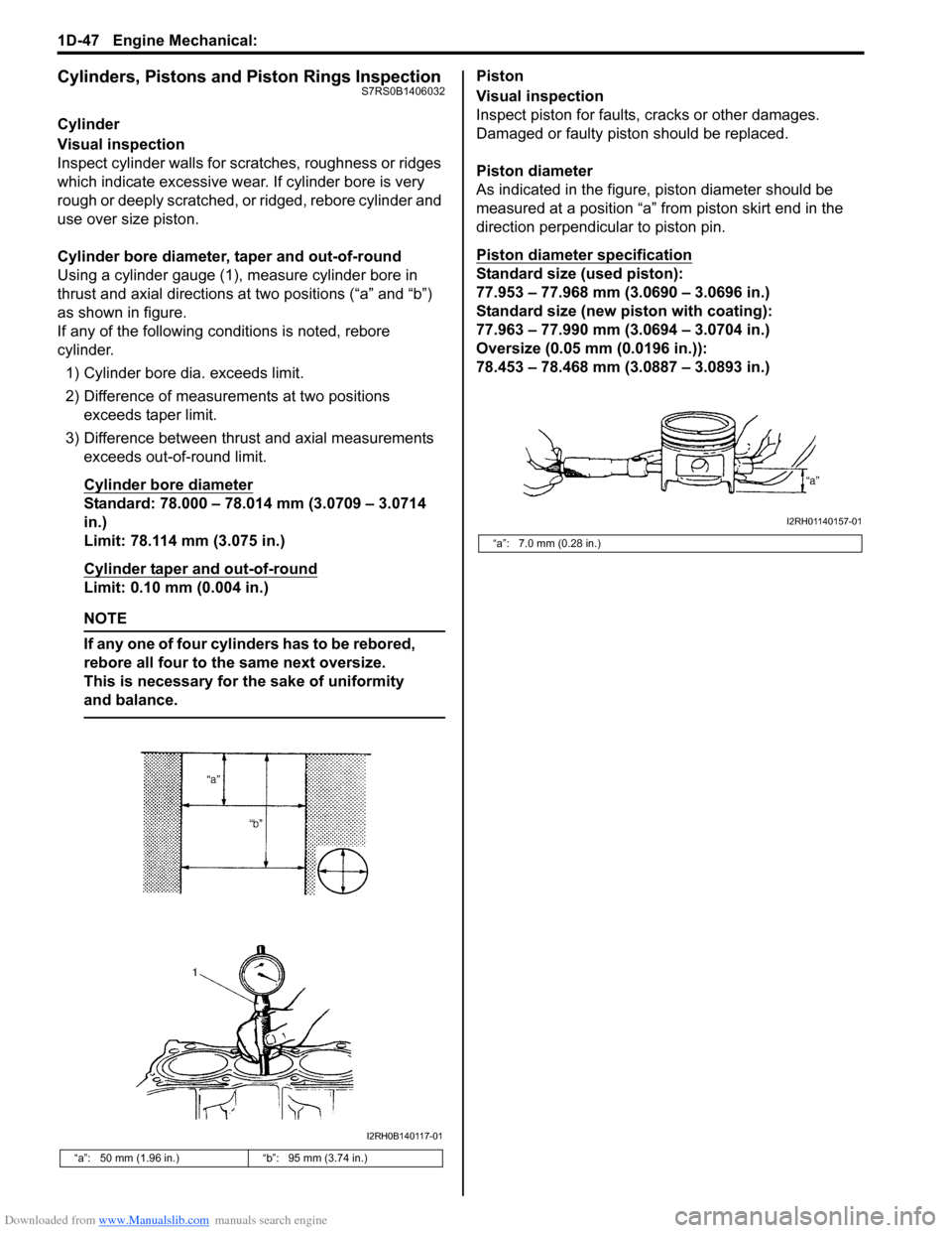
Using a cylinder gauge (1), measure cylinder bore in
thrust and axial directions at two positions (“a” and “b”)
as shown in figure.
If any of the following conditions is noted, rebore
cylinder.1) Cylinder bore dia. exceeds limit.
2) Difference of measurements at two positions exceeds taper limit.
3) Difference between thrust and axial measurements exceeds out-of-round limit.
Cylinder bore diameter
Standard: 78.000 – 78.014 mm (3.0709 – 3.0714
in.)
Limit: 78.114 mm (3.075 in.)
Cylinder taper and out-of-round
Limit: 0.10 mm (0.004 in.)
NOTE
If any one of four cylinders has to be rebored,
rebore all four to the same next oversize.
This is necessary for the sake of uniformity
and balance.
Piston
Visual inspection
Inspect piston for faults, cracks or other damages.
Damaged or faulty piston should be replaced.
Piston diameter
As indicated in the figure, piston diameter should be
measured at a position “a” from piston skirt end in the
direction perpendicular to piston pin.
Piston diameter specification
Standard size (used piston):
77.953 – 77.968 mm (3.0690 – 3.0696 in.)
Standard size (new piston with coating):
77.963 – 77.990 mm (3.0694 – 3.0704 in.)
Oversize (0.05 mm (0.0196 in.)):
78.453 – 78.468 mm (3.0887 – 3.0893 in.)
“a”: 50 mm (1.96 in.) “b”: 95 mm (3.74 in.)
I2RH0B140117-01
“a”: 7.0 mm (0.28 in.)
I2RH01140157-01
Page 339 of 1496
Downloaded from www.Manualslib.com manuals search engine Engine Mechanical: 1D-54
Main Bearings, Crankshaft and Cylinder Block
Removal and Installation
S7RS0B1406036
Removal1) Remove engine assembly from vehicle referring to “Engine Assembly Removal and Installation”.
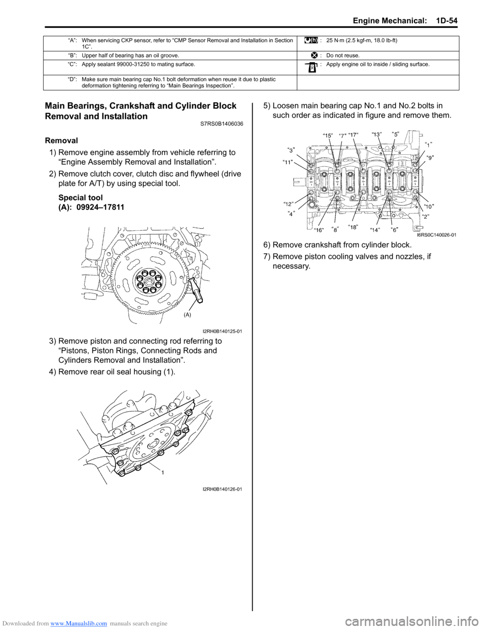
2) Remove clutch cover, clut ch disc and flywheel (drive
plate for A/T) by using special tool.
Special tool
(A): 09924–17811
3) Remove piston and connecting rod referring to “Pistons, Piston Rings, Connecting Rods and
Cylinders Removal and Installation”.
4) Remove rear oil seal housing (1). 5) Loosen main bearing cap No.1 and No.2 bolts in
such order as indicated in figure and remove them.
6) Remove crankshaft from cylinder block.
7) Remove piston cooling valves and nozzles, if necessary.
“A”: When servicing CKP sensor, refer to “CMP Sensor Removal and Installation in Section 1C”. :25 N
⋅m (2.5 kgf-m, 18.0 lb-ft)
“B”: Upper half of bearing has an oil groove. : Do not reuse.
“C”: Apply sealant 99000-31250 to mating surface. : Apply engine oil to inside / sliding surface.
“D”: Make sure main bearing cap No.1 bolt deformation when reuse it due to plastic deformation tightening referring to “Main Bearings Inspection”.
I2RH0B140125-01
I2RH0B140126-01
I6RS0C140026-01
Page 340 of 1496
Downloaded from www.Manualslib.com manuals search engine 1D-55 Engine Mechanical:
Installation
NOTE
• Use new bearing cap No.1 bolts. They are deformed once they are used because they
are plastic deformation tightening bolts.
• All parts to be insta lled must be perfectly
clean.
• Be sure to oil crankshaft journals, journal bearings, thrust bearings, crankpins,
connecting rod bearings, pistons, piston
rings and cylinder bores.
• Journal bearings, bearing caps, connecting rods, rod bearings, rod bearing
caps, pistons and piston rings are in
combination sets. Do not disturb such
combination and make sure that each part
goes back to where it came from, when
installing.
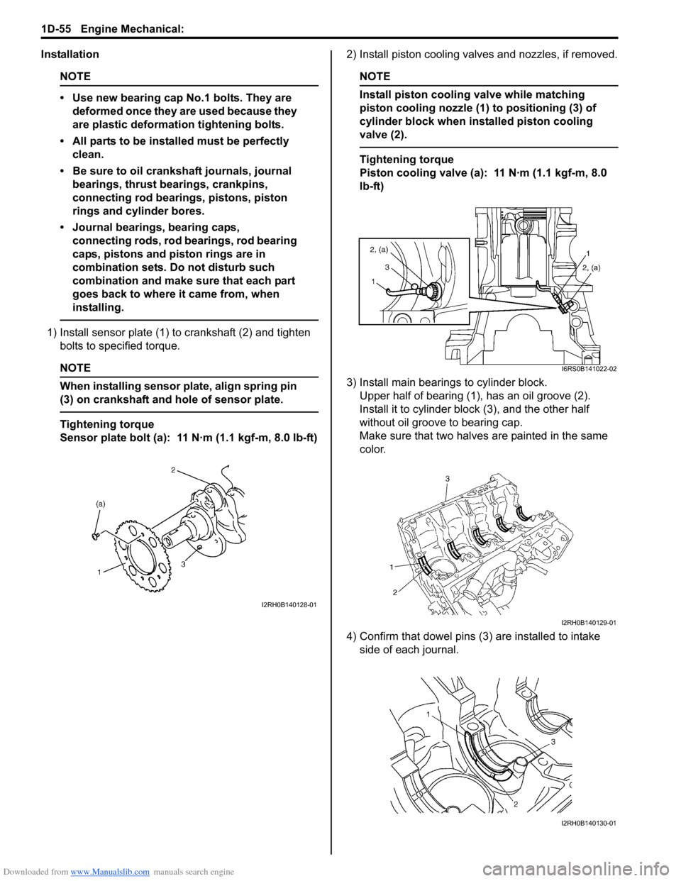
1) Install sensor plate (1) to crankshaft (2) and tighten bolts to spec ified torque.
NOTE
When installing sensor plate, align spring pin
(3) on crankshaft and hole of sensor plate.
Tightening torque
Sensor plate bolt (a): 11 N·m (1.1 kgf-m, 8.0 lb-ft) 2) Install piston cooling valves and nozzles, if removed.
NOTE
Install piston cooling valve while matching
piston cooling nozzle (1) to positioning (3) of
cylinder block when installed piston cooling
valve (2).
Tightening torque
Piston cooling valve (a): 11 N·m (1.1 kgf-m, 8.0
lb-ft)
3) Install main bearings to cylinder block. Upper half of bearing (1), has an oil groove (2).
Install it to cylinder block (3), and the other half
without oil groove to bearing cap.
Make sure that two halves are painted in the same
color.
4) Confirm that dowel pins (3 ) are installed to intake
side of each journal.
I2RH0B140128-01
I6RS0B141022-02
I2RH0B140129-01
I2RH0B140130-01
Page 342 of 1496
Downloaded from www.Manualslib.com manuals search engine 1D-57 Engine Mechanical:
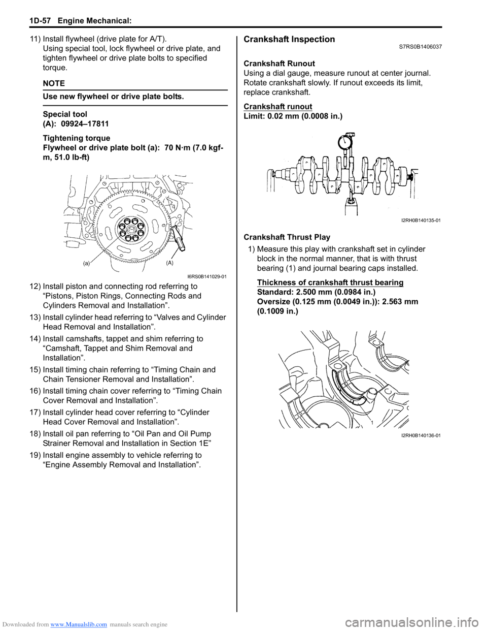
11) Install flywheel (drive plate for A/T).Using special tool, lock flyw heel or drive plate, and
tighten flywheel or drive plate bolts to specified
torque.
NOTE
Use new flywheel or drive plate bolts.
Special tool
(A): 09924–17811
Tightening torque
Flywheel or drive plate bolt (a): 70 N·m (7.0 kgf-
m, 51.0 lb-ft)
12) Install piston and connecting rod referring to “Pistons, Piston Rings, Connecting Rods and
Cylinders Removal and Installation”.
13) Install cylinder head referring to “Valves and Cylinder Head Removal and Installation”.
14) Install camshafts, tappet and shim referring to “Camshaft, Tappet and Shim Removal and
Installation”.
15) Install timing chain referring to “Timing Chain and Chain Tensioner Removal and Installation”.
16) Install timing chain cover referring to “Timing Chain Cover Removal and Installation”.
17) Install cylinder head cover referring to “Cylinder Head Cover Removal and Installation”.
18) Install oil pan referring to “Oil Pan and Oil Pump
Strainer Removal and Installation in Section 1E”
19) Install engine assembly to vehicle referring to “Engine Assembly Removal and Installation”.
Crankshaft InspectionS7RS0B1406037
Crankshaft Runout
Using a dial gauge, measure runout at center journal.
Rotate crankshaft slowly. If runout exceeds its limit,
replace crankshaft.
Crankshaft runout
Limit: 0.02 mm (0.0008 in.)
Crankshaft Thrust Play
1) Measure this play with crankshaft set in cylinder block in the normal manner, that is with thrust
bearing (1) and journal bearing caps installed.
Thickness of crankshaft thrust bearing
Standard: 2.500 mm (0.0984 in.)
Oversize (0.125 mm (0.0049 in.)): 2.563 mm
(0.1009 in.)
I6RS0B141029-01
I2RH0B140135-01
I2RH0B140136-01
Page 350 of 1496
Downloaded from www.Manualslib.com manuals search engine 1D-65 Engine Mechanical:
NOTE
The specified tightening torque is also described in the following.
“Air Cleaner Components”
“Throttle Body and Intake Manifold Components”
“Engine Mountings Components”
“Timing Chain Cover Components”
“Timing Chain and Chain Tensioner Components”
“Camshaft, Tappet and Shim Components”
“Valves and Cylinder Head Components”
“Pistons, Piston Rings, Connecting Rods and Cylinders Components”
“Main Bearings, Crankshaft and Cylinder Block Components”
Reference:
For the tightening torque of fastener not specified in this section, refer to “Fasteners Information in Section 0A”.
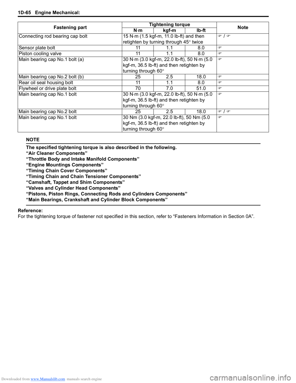
Connecting rod bearing cap bolt
15 N⋅m (1.5 kgf-m, 11.0 lb-ft) and then
retighten by turning through 45 ° twice �)
/ �)
Sensor plate bolt 111.1 8.0 �)
Piston cooling valve 111.1 8.0 �)
Main bearing cap No.1 bolt (a) 30 N⋅m (3.0 kgf-m, 22.0 lb-ft), 50 N ⋅m (5.0
kgf-m, 36.5 lb-ft) and then retighten by
turning through 60 ° �)
Main bearing cap No.2 bolt (b) 252.5 18.0 �)
Rear oil seal housing bolt 111.1 8.0 �)
Flywheel or drive plate bolt 707.0 51.0 �)
Main bearing cap No.1 bolt 30 N⋅m (3.0 kgf-m, 22.0 lb-ft), 50 N ⋅m (5.0
kgf-m, 36.5 lb-ft) and then retighten by
turning through 60 ° �)
Main bearing cap No.2 bolt 252.5 18.0 �) / �)
Main bearing cap No.1 bolt 30 Nm (3.0 kgf-m, 22.0 lb-ft), 50 Nm (5.0
kgf-m, 36.5 lb-ft) and then retighten by
turning through 60 ° �)
Fastening part
Tightening torque
Note
N ⋅mkgf-mlb-ft
Page 351 of 1496
Downloaded from www.Manualslib.com manuals search engine Engine Mechanical: 1D-66
Special Tools and Equipment
Recommended Service MaterialS7RS0B1408001
NOTE
Required service material is also described in the following.
“Timing Chain Cover Components”
“Timing Chain and Chain Tensioner Components”
“Camshaft, Tappet and Shim Components”
“Valves and Cylinder Head Components”
“Pistons, Piston Rings, Connecting Rods and Cylinders Components”
“Main Bearings, Crankshaft and Cylinder Block Components”
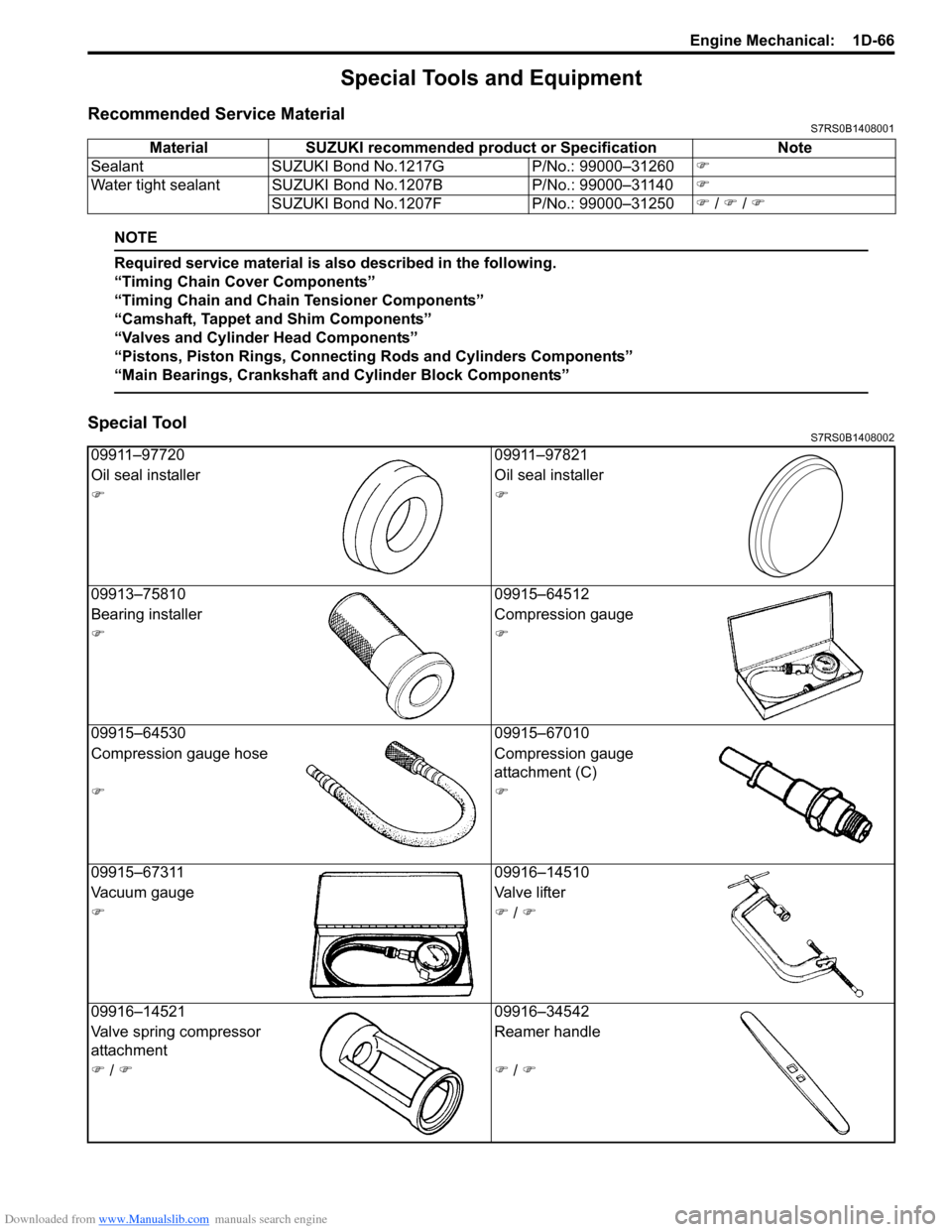
Special ToolS7RS0B1408002
Material SUZUKI recommended product or Specification Note
Sealant SUZUKI Bond No.1217G P/No.: 99000–31260�)
Water tight sealant SUZUKI Bond No.1207B P/No.: 99000–31140�)
SUZUKI Bond No.1207F P/No.: 99000–31250�) / �) / �)
09911–97720 09911–97821
Oil seal installer Oil seal installer
�)�)
09913–75810 09915–64512
Bearing installer Compression gauge
�)�)
09915–64530 09915–67010
Compression gauge hose Compression gauge
attachment (C)
�)�)
09915–67311 09916–14510
Vacuum gauge Valve lifter
�)�) / �)
09916–14521 09916–34542
Valve spring compressor
attachment Reamer handle
�) / �)�) / �)
Page 499 of 1496
Downloaded from www.Manualslib.com manuals search engine Brake Control System and Diagnosis: 4A-1
Brakes
Brake Control System and Diagnosis
Precautions
Precautions on BrakeS7RS0B4100001
Air Bag Warning
Refer to “Air Bag System Service Warning in Section 00”.
Brakes Diagnosis Note
Refer to “Brakes Diagnosis Note”.
General Description
Brakes ConstructionS7RS0B4101001
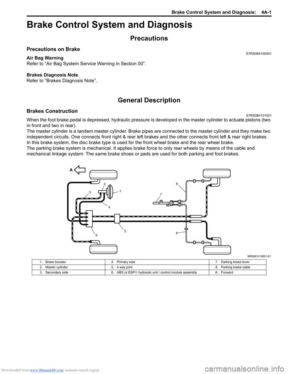
When the foot brake pedal is depressed, hydraulic pressure is developed in the master cylinder to actuate pistons (two
in front and two in rear).
The master cylinder is a tandem master cylinder. Brake pipes are connected to the master cylinder and they make two
independent circuits. One connects front right & rear left brakes and the other connects front left & rear right brakes.
In this brake system, the disc brake type is used for the front wheel brake and the rear wheel brake.
The parking brake system is mechanical. It applies brake force to only rear wheels by means of the cable and
mechanical linkage system. The same brake shoes or pads are used for both parking and foot brakes.
A
5
3
2
1
4
8
8
6
7
I6RS0C410001-01
1. Brake booster 4. Primary side 7. Parking brake lever
2. Master cylinder 5. 4 way joint 8. Parking brake cable
3. Secondary side 6. ABS or ESP® hydraulic unit / control module assembly A: Forward