2005 SUZUKI SWIFT Output shaft speed
[x] Cancel search: Output shaft speedPage 654 of 1496
Downloaded from www.Manualslib.com manuals search engine 5A-10 Automatic Transmission/Transaxle:
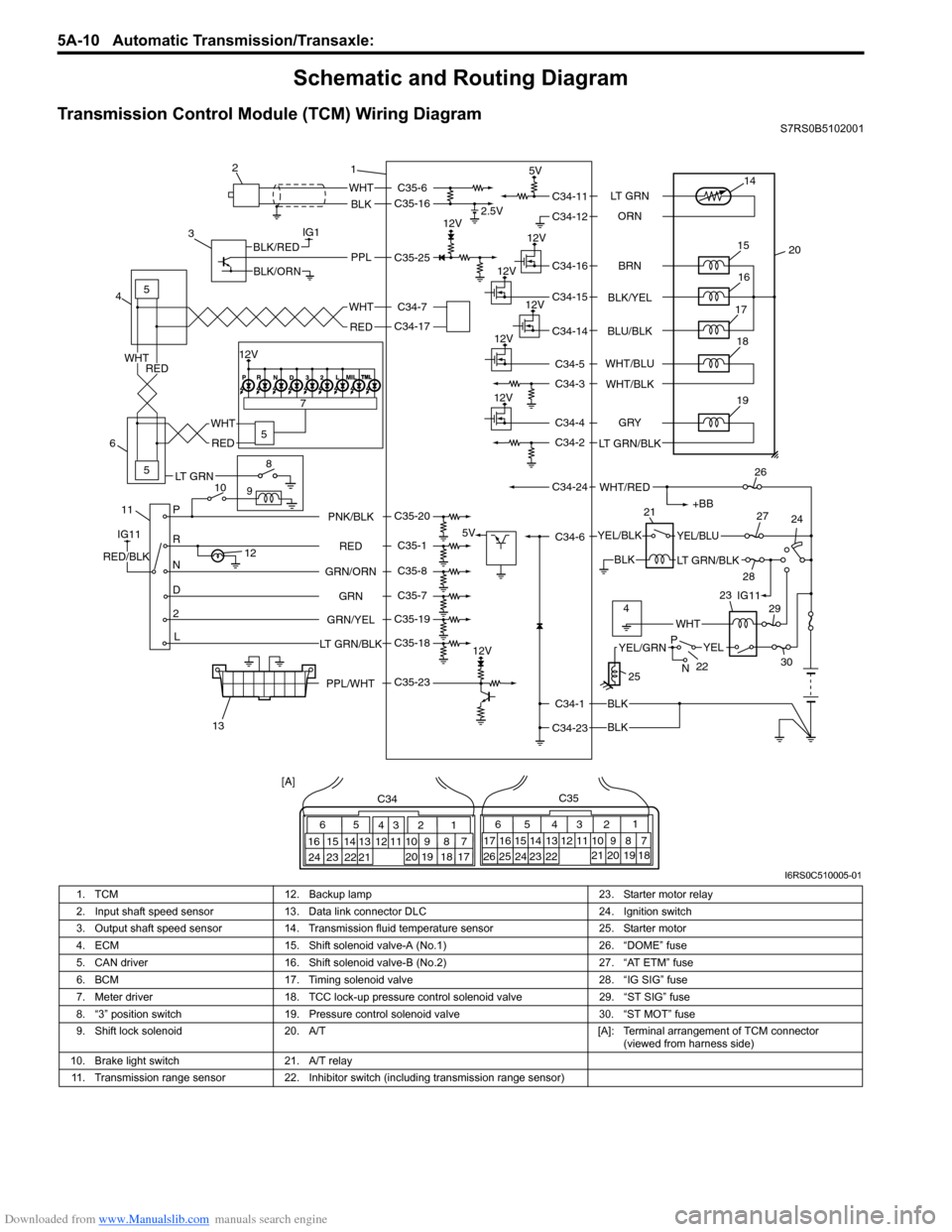
Schematic and Routing Diagram
Transmission Control Module (TCM) Wiring DiagramS7RS0B5102001
IG1
115
5
5
8
9
10 7
P
R
N
D
2
L
12
12V 2.5V
5V
12V
5V
12V
12V
12V
12V
WHT
BLK
BLK
BLK
BLK
PPLBLK/RED
BLK/ORN
IG11
RED/BLK
YEL/BLKYEL/BLU
LT GRN/BLK
+BB
WHT/RED
14
20
15
16
17
19
12V18
1
2
3
4
6
13 21
26
24
27
28 29
30
WHT
WHT
RED
RED
WHT
RED
65
16 15 14 13 12 11 43
24 23 2122 10 9 8 721
1920 18 17
C34
17 16
26 25
15 14
65 3
42
13 12
23 2224 11 10 9
21 20 19 87
18
1
C35
[A]
22
25
YELYEL/GRN
WHT
P
N
BRN
LT GRN
ORN
BLK/YEL
BLU/BLK
GRY
LT GRN/BLK WHT/BLU
WHT/BLK
C34-11
C34-12
C34-16
C34-15
C34-14
C34-4
C34-2
C34-1
C34-23 C34-6
C34-24 C34-5
C34-3
RED
GRN
GRN/ORN PNK/BLK
GRN/YEL
LT GRN/BLKC35-6
C35-16
C35-23 C35-25
C35-20
C35-1
C35-8
C35-7
C35-19
C35-18 C34-17 C34-7
4IG11
12V
23
PPL/WHT
LT GRN
I6RS0C510005-01
1. TCM 12. Backup lamp 23. Starter motor relay
2. Input shaft speed sensor 13. Data link connector DLC 24. Ignition switch
3. Output shaft speed sensor 14. Transmission fluid temperature sensor 25. Starter motor
4. ECM 15. Shift solenoid valve-A (No.1) 26. “DOME” fuse
5. CAN driver 16. Shift solenoid valve-B (No.2) 27. “AT ETM” fuse
6. BCM 17. Timing solenoid valve 28. “IG SIG” fuse
7. Meter driver 18. TCC lock-up pressure control solenoid valve 29. “ST SIG” fuse
8. “3” position switch 19. Pressure control solenoid valve 30. “ST MOT” fuse
9. Shift lock solenoid 20. A/T [A]: Terminal arrangement of TCM connector
(viewed from harness side)
10. Brake light switch 21. A/T relay
11. Transmission range sensor 22. Inhibitor switch (including transmission range sensor)
Page 658 of 1496
Downloaded from www.Manualslib.com manuals search engine 5A-14 Automatic Transmission/Transaxle:
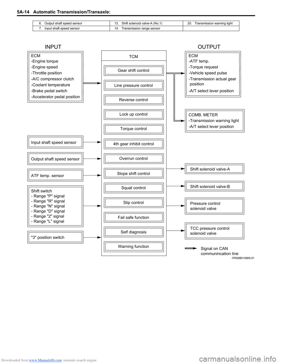
6. Output shaft speed sensor 13. Shift solenoid valve-A (No.1) 20. Transmission warning light
7. Input shaft speed sensor 14. Transmission range sensor
INPUT OUTPUT
TCMECM
Gear shift control
4th gear inhibit control
Slope shift control
Slip control
Lock up control
Torque control
Line pressure control
Overrun control
Reverse control
Squat control
Input shaft speed sensor
Output shaft speed sensor
"3" position switch ATF temp. sensor
Shift switch
- Range "P" signal
- Range "R" signal
- Range "N" signal
- Range "D" signal
- Range "2" signal
- Range "L" signal
Fail safe function
Self diagnosis
Warning function
ECM
Shift solenoid valve-A
Shift solenoid valve-B
TCC pressure control
solenoid valve
Pressure control
solenoid valve
Signal on CAN
communincation line
COMB. METER
-Engine torque
-Engine speed
-Throttle position
-A/C compressor clutch
-Coolant temperature
-Brake pedal switch -ATF temp.
-Torque request
-Vehicle speed pulse
-Transmission actual gear
position
-A/T select lever position
-Accelerator pedal position
-Transmission warning light
-A/T select lever position
I7RS0B510005-01
Page 665 of 1496
Downloaded from www.Manualslib.com manuals search engine Automatic Transmission/Transaxle: 5A-21
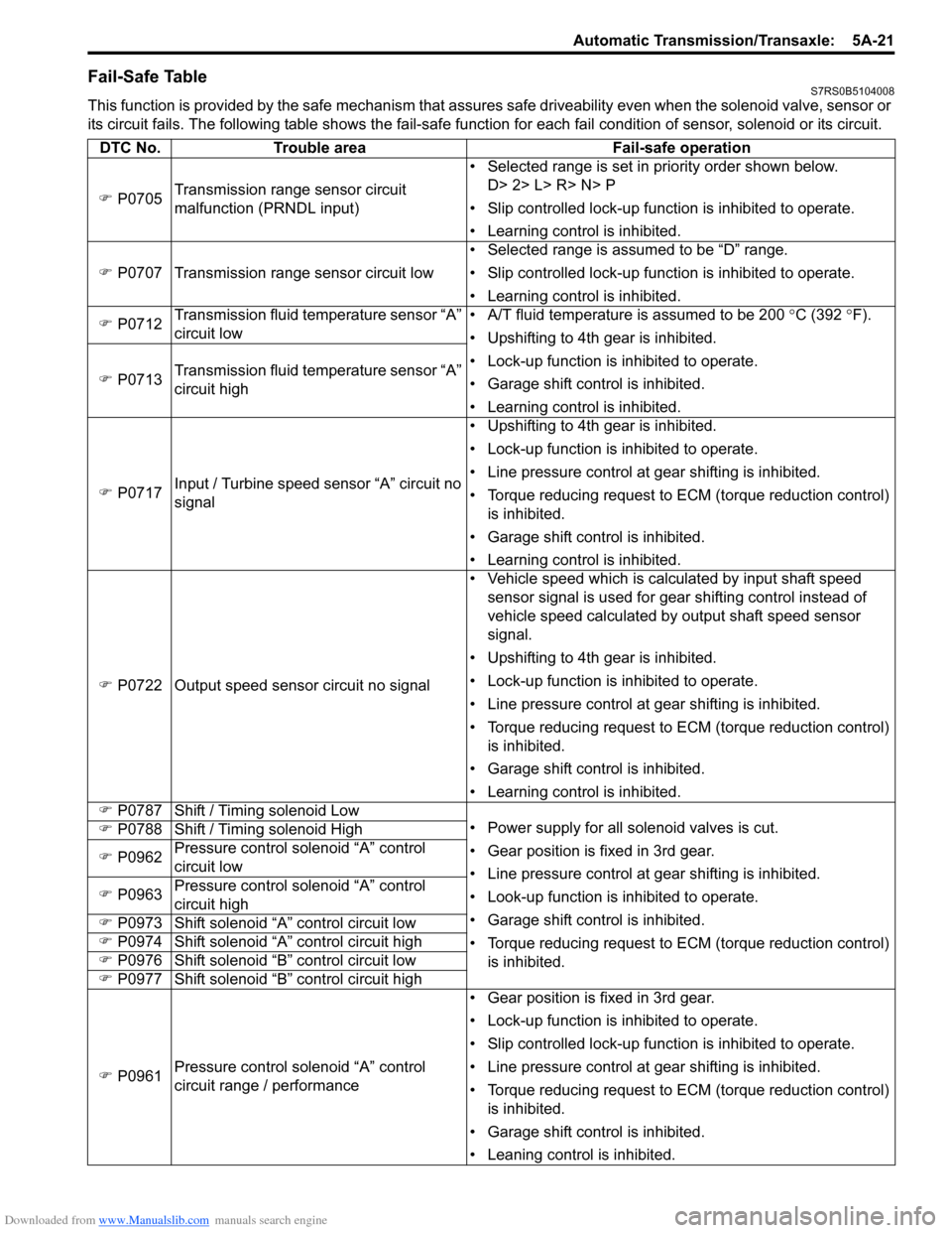
Fail-Safe TableS7RS0B5104008
This function is provided by the safe mechanism that assures safe driveability even when the solenoid valve, sensor or
its circuit fails. The following table shows th e fail-safe function for each fail condition of sensor, solenoid or its circuit.
DTC No. Trouble area Fail-safe operation
�) P0705 Transmission range sensor circuit
malfunction (PRNDL input) • Selected range is set in priority order shown below.
D> 2> L> R> N> P
• Slip controlled lock-up function is inhibited to operate.
• Learning control is inhibited.
�) P0707 Transmission range sensor circuit low • Selected range is assumed to be “D” range.
• Slip controlled lock-up function is inhibited to operate.
• Learning control is inhibited.
�) P0712 Transmission fluid temperature sensor “A”
circuit low • A/T fluid temperature is assumed to be 200
°C (392 °F).
• Upshifting to 4th gear is inhibited.
• Lock-up function is inhibited to operate.
• Garage shift control is inhibited.
• Learning control is inhibited.
�)
P0713 Transmission fluid temperature sensor “A”
circuit high
�) P0717 Input / Turbine speed sensor “A” circuit no
signal • Upshifting to 4th gear is inhibited.
• Lock-up function is inhibited to operate.
• Line pressure control at gear shifting is inhibited.
• Torque reducing request to ECM (torque reduction control)
is inhibited.
• Garage shift control is inhibited.
• Learning control is inhibited.
�) P0722 Output speed sensor circuit no signal • Vehicle speed which is calculated by input shaft speed
sensor signal is used for gear shifting control instead of
vehicle speed calculated by output shaft speed sensor
signal.
• Upshifting to 4th gear is inhibited.
• Lock-up function is inhibited to operate.
• Line pressure control at gear shifting is inhibited.
• Torque reducing request to ECM (torque reduction control) is inhibited.
• Garage shift control is inhibited.
• Learning control is inhibited.
�) P0787 Shift / Timing solenoid Low
• Power supply for all solenoid valves is cut.
• Gear position is fixed in 3rd gear.
• Line pressure control at gear shifting is inhibited.
• Look-up function is inhibited to operate.
• Garage shift control is inhibited.
• Torque reducing request to ECM (torque reduction control)
is inhibited.
�)
P0788 Shift / Timing solenoid High
�) P0962 Pressure control solenoid “A” control
circuit low
�) P0963 Pressure control solenoid “A” control
circuit high
�) P0973 Shift solenoid “A” control circuit low
�) P0974 Shift solenoid “A” control circuit high
�) P0976 Shift solenoid “B” control circuit low
�) P0977 Shift solenoid “B” control circuit high
�) P0961 Pressure control solenoid “A” control
circuit range / performance • Gear position is fixed in 3rd gear.
• Lock-up function is inhibited to operate.
• Slip controlled lock-up function is inhibited to operate.
• Line pressure control at gear shifting is inhibited.
• Torque reducing request to ECM (torque reduction control)
is inhibited.
• Garage shift control is inhibited.
• Leaning control is inhibited.
Page 668 of 1496
Downloaded from www.Manualslib.com manuals search engine 5A-24 Automatic Transmission/Transaxle:
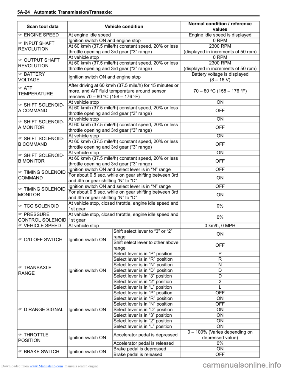
�) ENGINE SPEED At engine idle spee d Engine idle speed is displayed
�) INPUT SHAFT
REVOLUTION Ignition switch ON and engine stop 0 RPM
At 60 km/h (37.5 mile/h) constant speed, 20% or less
throttle opening and 3rd gear (“3” range)
2300 RPM
(displayed in increments of 50 rpm)
�) OUTPUT SHAFT
REVOLUTION At vehicle stop 0 RPM
At 60 km/h (37.5 mile/h) constant speed, 20% or less
throttle opening and 3rd gear (“3” range)
2300 RPM
(displayed in increments of 50 rpm)
�) BATTERY
VOLTAGE Ignition switch ON and engine stop Battery voltage is displayed
(8 – 16 V)
�) AT F
TEMPERATURE After driving at 60 km/h (37.5 mile/h) for 15 minutes or
more, and A/T fluid temperature around sensor
reaches 70 – 80
°C (158 – 176 °F) 70 – 80
°C (158 – 176 °F)
�) SHIFT SOLENOID-
A COMMAND At vehicle stop ON
At 60 km/h (37.5 mile/h) constant speed, 20% or less
throttle opening and 3rd gear (“3” range)
OFF
�) SHIFT SOLENOID-
A MONITOR At vehicle stop ON
At 60 km/h (37.5 mile/h) constant speed, 20% or less
throttle opening and 3rd gear (“3” range)
OFF
�) SHIFT SOLENOID-
B COMMAND At vehicle stop ON
At 60 km/h (37.5 mile/h) constant speed, 20% or less
throttle opening and 3rd gear (“3” range)
OFF
�) SHIFT SOLENOID-
B MONITOR At vehicle stop ON
At 60 km/h (37.5 mile/h) constant speed, 20% or less
throttle opening and 3rd gear (“3” range)
OFF
�) TIMING SOLENOID
COMMAND Ignition switch ON and sele
ct lever is in “N” range OFF
For about 0.5 sec. while on gear shifting between 3rd
and 4th or gear shifting “N” to “D” ON
�) TIMING SOLENOID
MONITOR Ignition switch ON and sele
ct lever is in “N” range OFF
For about 0.5 sec. while on gear shifting between 3rd
and 4th or gear shifting “N” to “D” ON
�) TCC SOLENOID At vehicle stop, closed throttle, engine idle speed and
1st gear 0%
�) PRESSURE
CONTROL SOLENOID At vehicle stop, closed throttle, engine idle speed and
1st gear
0%
�) VEHICLE SPEED At vehicle stop 0 km/h, 0 MPH
�) O/D OFF SWITCH Ignition switch ON Shift select lever to “3” or “2”
range
ON
Shift select lever to other above
range OFF
�) TRANSAXLE
RANGE Ignition switch ONSelect lever is in “P” position P
Select lever is in “R
” position R
Select lever is in “N” position N
Select lever is in “D” position D
Select lever is in “3” position D
Select lever is in “2” position 2
Select lever is in “L” position L
�) D RANGE SIGNAL Ignition switch ON Select lever is in “P” position
OFF
Select lever is in “R” position ON
Select lever is in “N” position OFF
Select lever is in “D” position ON
Select lever is in “3” position ON
Select lever is in “2” position ON
Select lever is in “L” position ON
�) THROTTLE
POSITION Ignition switch ONAccelerator peda
l is depressed 0 – 100% (Varies depending on
depressed value)
Accelerator peda l is released 0%
�) BRAKE SWITCH Ignition switch ON Brake pedal is depressed
ON
Brake pedal is released OFF
Scan tool data
Vehicle condition Normal condition / reference
values
Page 669 of 1496
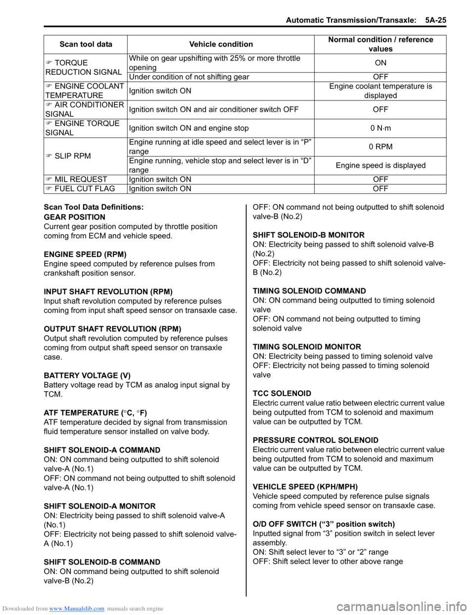
Downloaded from www.Manualslib.com manuals search engine Automatic Transmission/Transaxle: 5A-25
Scan Tool Data Definitions:
GEAR POSITION
Current gear position computed by throttle position
coming from ECM and vehicle speed.
ENGINE SPEED (RPM)
Engine speed computed by reference pulses from
crankshaft position sensor.
INPUT SHAFT REVOLUTION (RPM)
Input shaft revolution computed by reference pulses
coming from input shaft speed sensor on transaxle case.
OUTPUT SHAFT REVOLUTION (RPM)
Output shaft revolution computed by reference pulses
coming from output shaft speed sensor on transaxle
case.
BATTERY VOLTAGE (V)
Battery voltage read by TCM as analog input signal by
TCM.
ATF TEMPERATURE (°C, °F)
ATF temperature decided by signal from transmission
fluid temperature sensor installed on valve body.
SHIFT SOLENOID-A COMMAND
ON: ON command being outputted to shift solenoid
valve-A (No.1)
OFF: ON command not being outputted to shift solenoid
valve-A (No.1)
SHIFT SOLENOID-A MONITOR
ON: Electricity being passed to shift solenoid valve-A
(No.1)
OFF: Electricity not being passed to shift solenoid valve-
A (No.1)
SHIFT SOLENOID-B COMMAND
ON: ON command being outputted to shift solenoid
valve-B (No.2) OFF: ON command not being outputted to shift solenoid
valve-B (No.2)
SHIFT SOLENOID-B MONITOR
ON: Electricity being passed to shift solenoid valve-B
(No.2)
OFF: Electricity not being passed to shift solenoid valve-
B (No.2)
TIMING SOLENOID COMMAND
ON: ON command being outputted to timing solenoid
valve
OFF: ON command not being outputted to timing
solenoid valve
TIMING SOLENOID MONITOR
ON: Electricity being passed to timing solenoid valve
OFF: Electricity not being passed to timing solenoid
valve
TCC SOLENOID
Electric current value ratio between electric current value
being outputted from TCM to solenoid and maximum
value can be outputted by TCM.
PRESSURE CONTROL SOLENOID
Electric current value ratio between electric current value
being outputted from TCM to solenoid and maximum
value can be outputted by TCM.
VEHICLE SPEED (KPH/MPH)
Vehicle speed computed by reference pulse signals
coming from vehicle speed sensor on transaxle case.
O/D OFF SWITCH (“3” position switch)
Inputted signal from “3” position switch in select lever
assembly.
ON: Shift select lever to “3” or “2” range
OFF: Shift select lever to other above range
�)
TORQUE
REDUCTION SIGNAL While on gear upshifting with 25% or more throttle
opening
ON
Under condition of not shifting gear OFF
�) ENGINE COOLANT
TEMPERATURE Ignition switch ON Engine coolant temperature is
displayed
�) AIR CONDITIONER
SIGNAL Ignition switch ON and air conditioner switch OFF OFF
�) ENGINE TORQUE
SIGNAL Ignition switch ON and engine stop 0 N
⋅m
�) SLIP RPM Engine running at idle speed
and select lever is in “P”
range 0 RPM
Engine running, vehicle stop and select lever is in “D”
range Engine speed is displayed
�) MIL REQUEST Ignition switch ON OFF
�) FUEL CUT FLAG Ignition switch ON OFFScan tool data Vehicle condition
Normal condition / reference
values
Page 670 of 1496
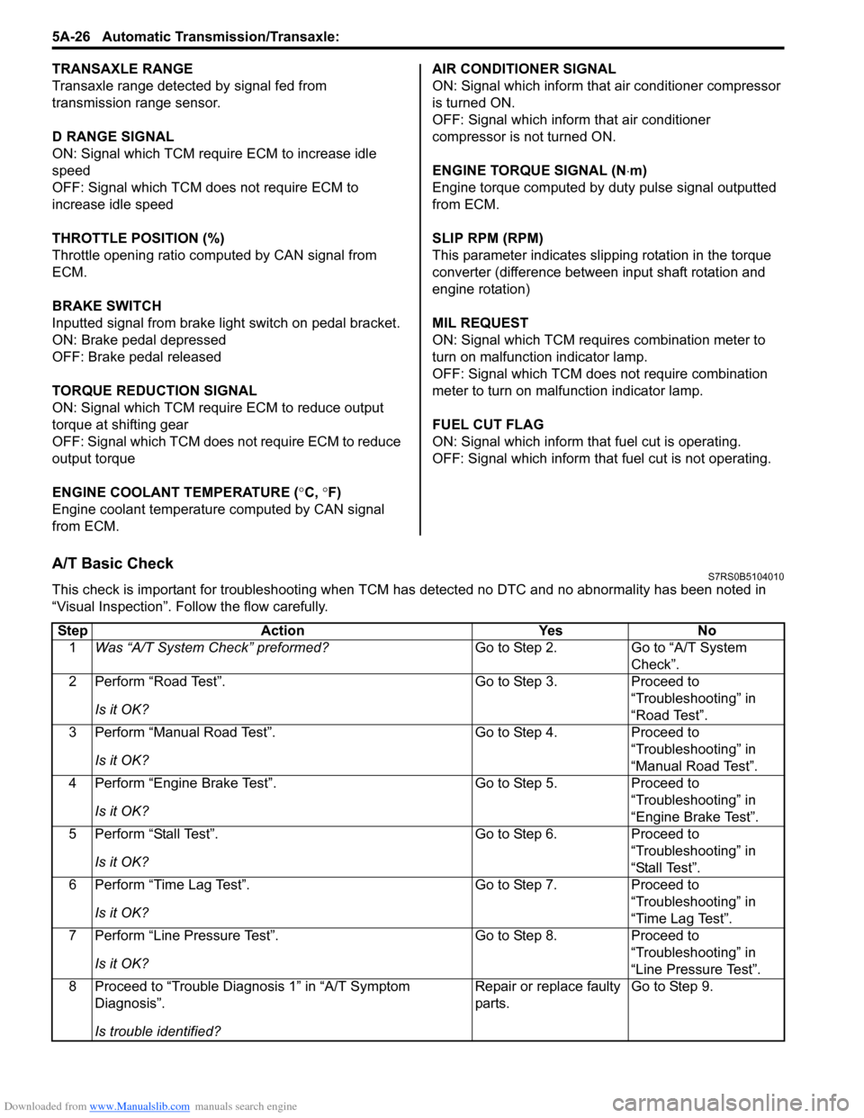
Downloaded from www.Manualslib.com manuals search engine 5A-26 Automatic Transmission/Transaxle:
TRANSAXLE RANGE
Transaxle range detected by signal fed from
transmission range sensor.
D RANGE SIGNAL
ON: Signal which TCM require ECM to increase idle
speed
OFF: Signal which TCM does not require ECM to
increase idle speed
THROTTLE POSITION (%)
Throttle opening ratio computed by CAN signal from
ECM.
BRAKE SWITCH
Inputted signal from brake light switch on pedal bracket.
ON: Brake pedal depressed
OFF: Brake pedal released
TORQUE REDUCTION SIGNAL
ON: Signal which TCM require ECM to reduce output
torque at shifting gear
OFF: Signal which TCM does not require ECM to reduce
output torque
ENGINE COOLANT TEMPERATURE ( °C, °F)
Engine coolant temperature computed by CAN signal
from ECM. AIR CONDITIONER SIGNAL
ON: Signal which inform that air conditioner compressor
is turned ON.
OFF: Signal which inform that air conditioner
compressor is not turned ON.
ENGINE TORQUE SIGNAL (N
⋅m)
Engine torque computed by duty pulse signal outputted
from ECM.
SLIP RPM (RPM)
This parameter indicates slip ping rotation in the torque
converter (difference between input shaft rotation and
engine rotation)
MIL REQUEST
ON: Signal which TCM requires combination meter to
turn on malfunction indicator lamp.
OFF: Signal which TCM does not require combination
meter to turn on malf unction indicator lamp.
FUEL CUT FLAG
ON: Signal which inform that fuel cut is operating.
OFF: Signal which inform that fuel cut is not operating.
A/T Basic CheckS7RS0B5104010
This check is important for troubleshooting when TCM has detected no DTC and no abnormality has been noted in
“Visual Inspection”. Fo llow the flow carefully.
Step Action YesNo
1 Was “A/T System Check” preformed? Go to Step 2.Go to “A/T System
Check”.
2 Perform “Road Test”.
Is it OK? Go to Step 3.
Proceed to
“Troubleshooting” in
“Road Test”.
3 Perform “Manual Road Test”.
Is it OK? Go to Step 4.
Proceed to
“Troubleshooting” in
“Manual Road Test”.
4 Perform “Engine Brake Test”.
Is it OK? Go to Step 5.
Proceed to
“Troubleshooting” in
“Engine Brake Test”.
5 Perform “Stall Test”.
Is it OK? Go to Step 6.
Proceed to
“Troubleshooting” in
“Stall Test”.
6 Perform “Time Lag Test”.
Is it OK? Go to Step 7.
Proceed to
“Troubleshooting” in
“Time Lag Test”.
7 Perform “Line Pressure Test”.
Is it OK? Go to Step 8.
Proceed to
“Troubleshooting” in
“Line Pressure Test”.
8 Proceed to “Trouble Diag nosis 1” in “A/T Symptom
Diagnosis”.
Is trouble identified? Repair or replace faulty
parts.
Go to Step 9.
Page 671 of 1496
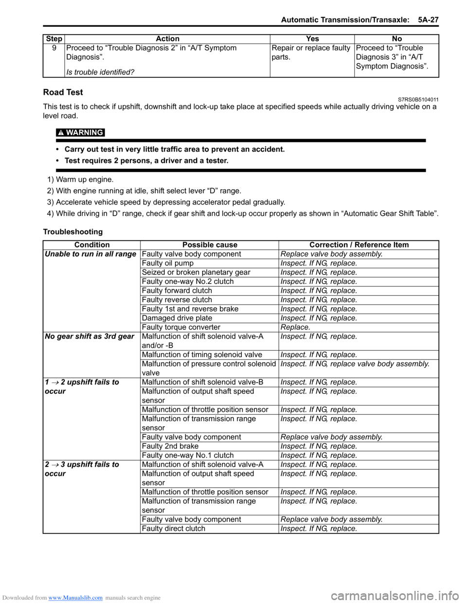
Downloaded from www.Manualslib.com manuals search engine Automatic Transmission/Transaxle: 5A-27
Road TestS7RS0B5104011
This test is to check if upshift, downshift and lock-up take place at specified speeds while actually driving vehicle on a
level road.
WARNING!
• Carry out test in very little traffic area to prevent an accident.
• Test requires 2 persons, a driver and a tester.
1) Warm up engine.
2) With engine running at idle, shift select lever “D” range.
3) Accelerate vehicle speed by depressing accelerator pedal gradually.
4) While driving in “D” range, check if gear shift and lock-up occur properly as shown in “Automatic Gear Shift Table”.
Troubleshooting 9 Proceed to “Trouble Diag
nosis 2” in “A/T Symptom
Diagnosis”.
Is trouble identified? Repair or replace faulty
parts.
Proceed to “Trouble
Diagnosis 3” in “A/T
Symptom Diagnosis”.
Step Action Yes No
Condition
Possible cause Correction / Reference Item
Unable to run in all range Faulty valve body component Replace valve body assembly.
Faulty oil pump Inspect. If NG, replace.
Seized or broken planetary gear Inspect. If NG, replace.
Faulty one-way No.2 clutch Inspect. If NG, replace.
Faulty forward clutch Inspect. If NG, replace.
Faulty reverse clutch Inspect. If NG, replace.
Faulty 1st and reverse brake Inspect. If NG, replace.
Damaged drive plate Inspect. If NG, replace.
Faulty torque converter Replace.
No gear shift as 3rd gear Malfunction of shift solenoid valve-A
and/or -B Inspect. If NG, replace.
Malfunction of timing solenoid valve Inspect. If NG, replace.
Malfunction of pressure control solenoid
valve Inspect. If NG, replace valve body assembly.
1
→ 2 upshift fails to
occur Malfunction of shif
t solenoid valve-B Inspect. If NG, replace.
Malfunction of output shaft speed
sensor Inspect. If NG, replace.
Malfunction of throttle position sensor Inspect. If NG, replace.
Malfunction of transmission range
sensor Inspect. If NG, replace.
Faulty valve body component Replace valve body assembly.
Faulty 2nd brake Inspect. If NG, replace.
Faulty one-way No.1 clutch Inspect. If NG, replace.
2
→ 3 upshift fails to
occur Malfunction of shif
t solenoid valve-A Inspect. If NG, replace.
Malfunction of output shaft speed
sensor Inspect. If NG, replace.
Malfunction of throttle position sensor Inspect. If NG, replace.
Malfunction of transmission range
sensor Inspect. If NG, replace.
Faulty valve body component Replace valve body assembly.
Faulty direct clutch Inspect. If NG, replace.
Page 672 of 1496
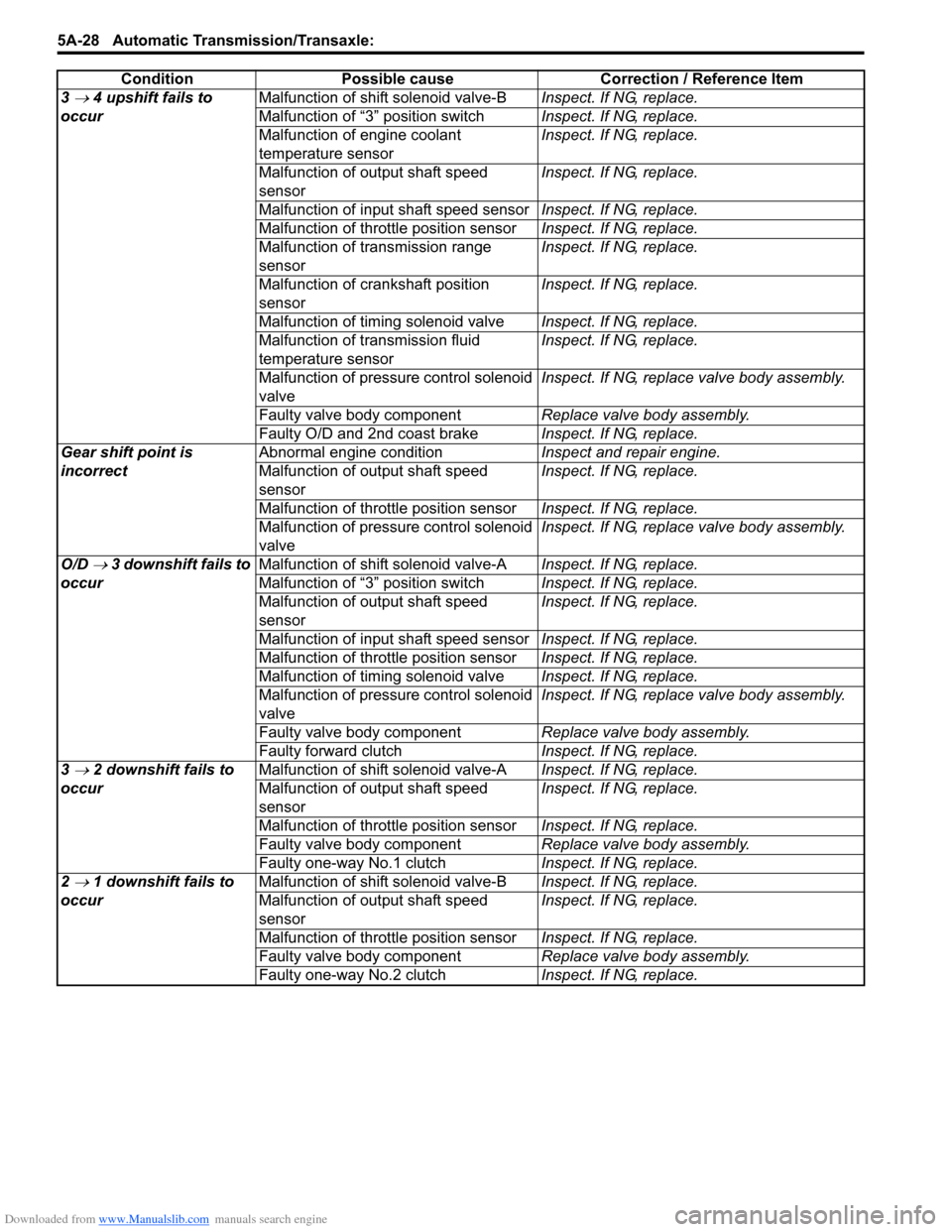
Downloaded from www.Manualslib.com manuals search engine 5A-28 Automatic Transmission/Transaxle:
3 → 4 upshift fails to
occur Malfunction of shift solenoid valve-B
Inspect. If NG, replace.
Malfunction of “3” position switch Inspect. If NG, replace.
Malfunction of engine coolant
temperature sensor Inspect. If NG, replace.
Malfunction of output shaft speed
sensor Inspect. If NG, replace.
Malfunction of input shaft speed sensor Inspect. If NG, replace.
Malfunction of throttle position sensor Inspect. If NG, replace.
Malfunction of transmission range
sensor Inspect. If NG, replace.
Malfunction of crankshaft position
sensor Inspect. If NG, replace.
Malfunction of timing solenoid valve Inspect. If NG, replace.
Malfunction of transmission fluid
temperature sensor Inspect. If NG, replace.
Malfunction of pressure control solenoid
valve Inspect. If NG, replace valve body assembly.
Faulty valve body component Replace valve body assembly.
Faulty O/D and 2nd coast brake Inspect. If NG, replace.
Gear shift point is
incorrect Abnormal engine condition
Inspect and repair engine.
Malfunction of output shaft speed
sensor Inspect. If NG, replace.
Malfunction of throttle position sensor Inspect. If NG, replace.
Malfunction of pressure control solenoid
valve Inspect. If NG, replace valve body assembly.
O/D
→ 3 downshift fails to
occur Malfunction of shift solenoid valve-A
Inspect. If NG, replace.
Malfunction of “3” position switch Inspect. If NG, replace.
Malfunction of output shaft speed
sensor Inspect. If NG, replace.
Malfunction of input shaft speed sensor Inspect. If NG, replace.
Malfunction of throttle position sensor Inspect. If NG, replace.
Malfunction of timing solenoid valve Inspect. If NG, replace.
Malfunction of pressure control solenoid
valve Inspect. If NG, replace valve body assembly.
Faulty valve body component Replace valve body assembly.
Faulty forward clutch Inspect. If NG, replace.
3
→ 2 downshift fails to
occur Malfunction of shift solenoid valve-A
Inspect. If NG, replace.
Malfunction of output shaft speed
sensor Inspect. If NG, replace.
Malfunction of throttle position sensor Inspect. If NG, replace.
Faulty valve body component Replace valve body assembly.
Faulty one-way No.1 clutch Inspect. If NG, replace.
2
→ 1 downshift fails to
occur Malfunction of shift solenoid valve-B
Inspect. If NG, replace.
Malfunction of output shaft speed
sensor Inspect. If NG, replace.
Malfunction of throttle position sensor Inspect. If NG, replace.
Faulty valve body component Replace valve body assembly.
Faulty one-way No.2 clutch Inspect. If NG, replace.
Condition Possible cause Correction / Reference Item