2005 SUZUKI SWIFT fuel pipe
[x] Cancel search: fuel pipePage 9 of 1496
Downloaded from www.Manualslib.com manuals search engine Precautions: 00-4
General PrecautionsS7RS0B0000002
The WARNING and CAUTION describe some general
precautions that you should observe when servicing a
vehicle. These general precautions apply to many of the
service procedures, and they will not necessarily be
repeated with each procedure to which they apply.
WARNING!
• Whenever raising a vehicle for service, be sure to follow the instructions under
“Vehicle Lifting Points in Section 0A”.
• When it is necessary to do service work with the engine running, make sure that
the parking brake is set fully and the
transmission is in Neutral (for manual
transmission vehicles) or Park (for
automatic transmission vehicles), Keep
hands, hair, clothing, tools, etc. away from
the fan and belts when the engine is
running.
• When it is necessary to run the engine indoors, make sure that the exhaust gas is
forced outdoors.
• Do not perform service work in areas where combustible materials can come in
contact with a hot exhaust system. When
working with toxic or flammable materials
(such as gasoline and refrigerant), make
sure that the area you work in is well-
ventilated.
• To avoid getting burned, keep away from hot metal parts such as the radiator,
exhaust manifold, tail pipe, muffler, etc.
• New and used engine oil can be hazardous. Children and pets may be
harmed by swallowing new or used oil.
Keep new and used oil and used engine oil
filters away from children and pets.
Continuous contact with used engine oil
has been found to cause [skin] cancer in
laboratory animals. Brief contact with used
oil may irritate skin. To minimize your
exposure to used engine oil, wear a long-
sleeve shirt and moisture-proof gloves
(such as dish washing gloves) when
changing engine oil. If engine oil contacts
your skin, wash thoroughly with soap and
water. Launder any clothing or rags if wet
with oil, recycle or properly dispose of
used oil and filters. • Be sure to observe following instructions
when handling service materials such as
fuel, oil, fluid, coolant, grease, sealant,
thread lock cement, etc. Otherwise, your
health may be ruined.
– Whenever handling any of these service materials, wear safety glasses to protect
your eyes. If it gets into your eye, it may
cause inflammation.
– Whenever handling any of these service materials, wear moistu re-proof gloves to
protect your skin. If it adheres to your
skin, it may cause inflammation.
– Do not swallow any of these service materials. It would cause diarrhea or
nausea.
– Keep all these materials out of children’s reach.
• Make sure the bonnet is fully closed and latched before driving. If it is not, it can fly
up unexpectedly during driving,
obstructing your view and resulting in an
accident.
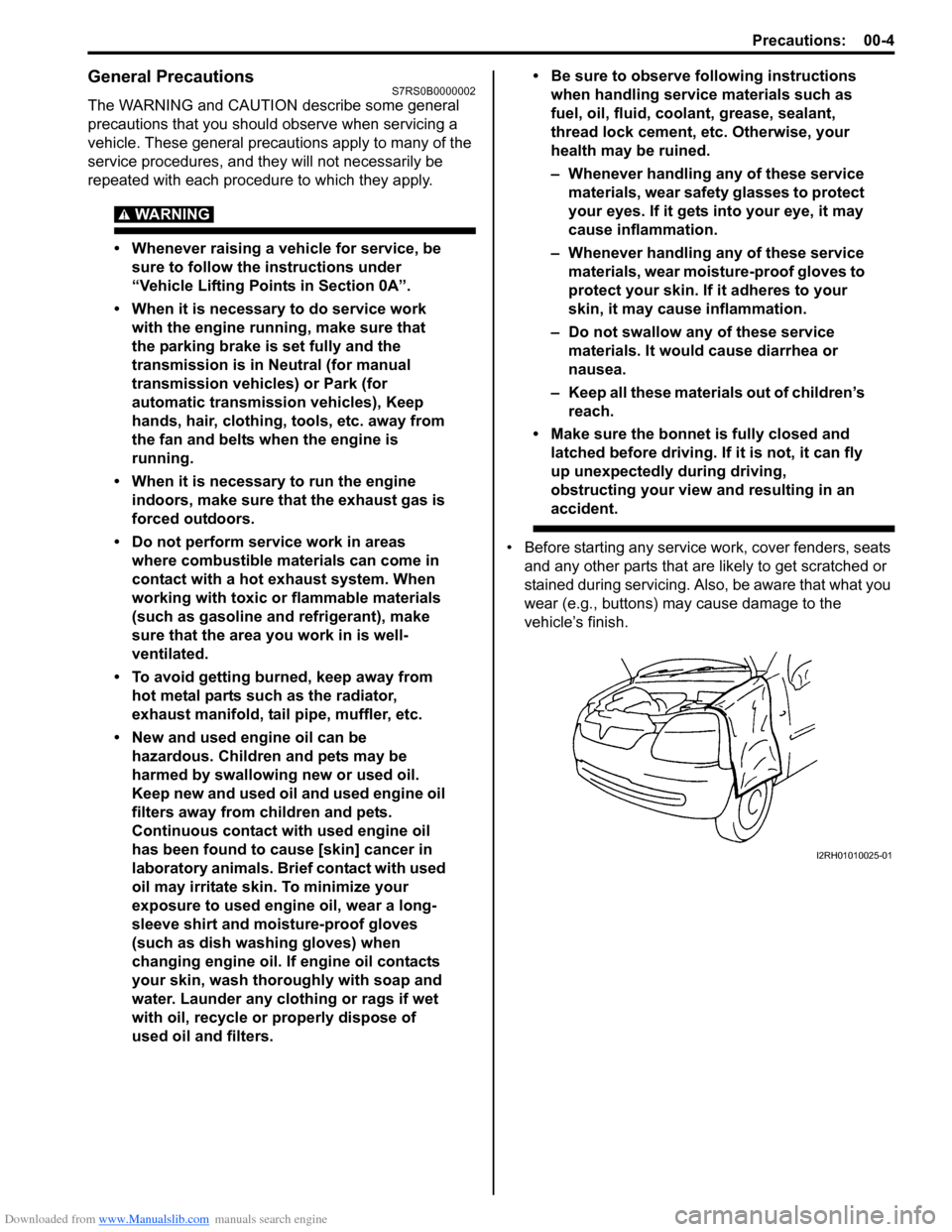
• Before starting any service work, cover fenders, seats and any other parts that are likely to get scratched or
stained during servicing. Also, be aware that what you
wear (e.g., buttons) ma y cause damage to the
vehicle’s finish.
I2RH01010025-01
Page 21 of 1496
Downloaded from www.Manualslib.com manuals search engine Table of Contents 0- i
0
Section 0
CONTENTS
General Information
General Information ................................ 0A-1
General Description ............................................. 0A-1
Abbreviations ...................................................... 0A-1
Symbols .............................................................. 0A-2
Wire Color Symbols ............................................ 0A-2
Fasteners Information ......................................... 0A-3
Vehicle Lifting Points ........................................... 0A-5
Engine Supporting Points ................................... 0A-7
Vehicle Identification Number ............................. 0A-7
Engine Identification Number .............................. 0A-7
Transmission Identification Number .................... 0A-7
Component Locatio n ........................................... 0A-8
Warning, Caution and Information Labels Location ............................................................ 0A-8
Maintenance and Lubricat ion ................. 0B-1
Precautions........................................................... 0B-1
Precautions for Maintenance and Lubrication ..... 0B-1
Scheduled Maintenance ...................................... 0B-1 Maintenance Schedule under Normal Driving Conditions ......................................................... 0B-1
Maintenance Recommended under Severe Driving Conditions ............................................. 0B-2
Repair Instructions .............................................. 0B-3 Accessory Drive Belt Inspection.......................... 0B-3
Accessory Drive Belt Repl acement ..................... 0B-4
Valve Lash (Clearance) Inspection ..................... 0B-4
Engine Oil and Filter Change .............................. 0B-4
Engine Coolant Change ...... ................................ 0B-5
Exhaust System Inspection ................................. 0B-6
Spark Plug Replacement .................................... 0B-6
Air Cleaner Filter Inspection ................................ 0B-6
Air Cleaner Filter Replac ement ........................... 0B-6 Fuel Lines and Connections Inspection .............. 0B-6
Fuel Filter Replacement ...................................... 0B-7
Fuel Tank Inspection ........................................... 0B-7
PCV Valve Inspection ......................................... 0B-7
Fuel Evaporative Emission Control System
Inspection .......................................................... 0B-7
Brake Discs and Pads Inspection ....................... 0B-7
Brake Hoses and Pipes Inspection ..................... 0B-7
Brake Fluid Inspection......................................... 0B-8
Brake Fluid Replacement .................................... 0B-8
Brake Lever and Cable Inspection ...................... 0B-8
Clutch Fluid Inspection ........................................ 0B-8
Tires Inspection ................................................... 0B-9
Wheel Discs Inspection ....................................... 0B-9
Wheel Bearing Inspection ................................... 0B-9
Suspension System Inspection ........................... 0B-9
Steering System Inspection .............................. 0B-10
Drive Shaft (Axle) Boots Inspection .................. 0B-10
Manual Transaxle Oil Inspection ....................... 0B-10
Manual Transaxle Oil Replacement .................. 0B-10
Automatic Transaxle Fluid Level Inspection...... 0B-11
Automatic Transaxle Fluid Replacement .......... 0B-11
Automatic Transaxle Fluid Cooler Hose Inspection ........................................................ 0B-11
All Latches, Hinges and Locks Inspection......... 0B-11
HVAC Air Filter (If Equipped) Inspection ........... 0B-12
HVAC Air Filter (If Equipped) Replacement ...... 0B-12
Final Inspection for Maint enance Service ......... 0B-12
Specifications .................... .................................0B-13
Tightening Torque Specifications ...................... 0B-13
Special Tools and Equipmen t ...........................0B-13
Recommended Fluids and Lubricants............... 0B-13
Special Tool ...................................................... 0B-14
Page 26 of 1496

Downloaded from www.Manualslib.com manuals search engine 0A-5 General Information:
Vehicle Lifting PointsS7RS0B0101005
WARNING!
• Before applying hoist to underbody, always take vehicle balance throughout service into
consideration. Vehicle balance on hoist may change depending on what part to be removed.
• Before lifting up the vehicle, check to be sure that end of hoist arm is not in contact with brake pipe,
fuel pipe, bracket or any other part.
• When using frame contact hoist, apply hoist as shown (right and left at the same position). Lift up
the vehicle till 4 tires are a little off the ground and make sure that the vehicle will not fall off by
trying to move vehicle body in both ways. Work can be started only after this confirmation.
• Make absolutely sure to lock hoist after vehicle is hoisted up.
When Using Frame Contact Hoist
1
:2
:3
4
4
I4RS0A010001-01
1. Vehicle front
3. Floor jack position
2. Support position for frame contact hoist and safety stand 4. Body mounting stay
Page 31 of 1496
Downloaded from www.Manualslib.com manuals search engine Maintenance and Lubrication: 0B-1
General Information
Maintenance and Lubrication
Precautions
Precautions for Maintenance and LubricationS7RS0B0200001
Air Bag Warning
Refer to “Air Bag Warning in Section 00”.
Scheduled Maintenance
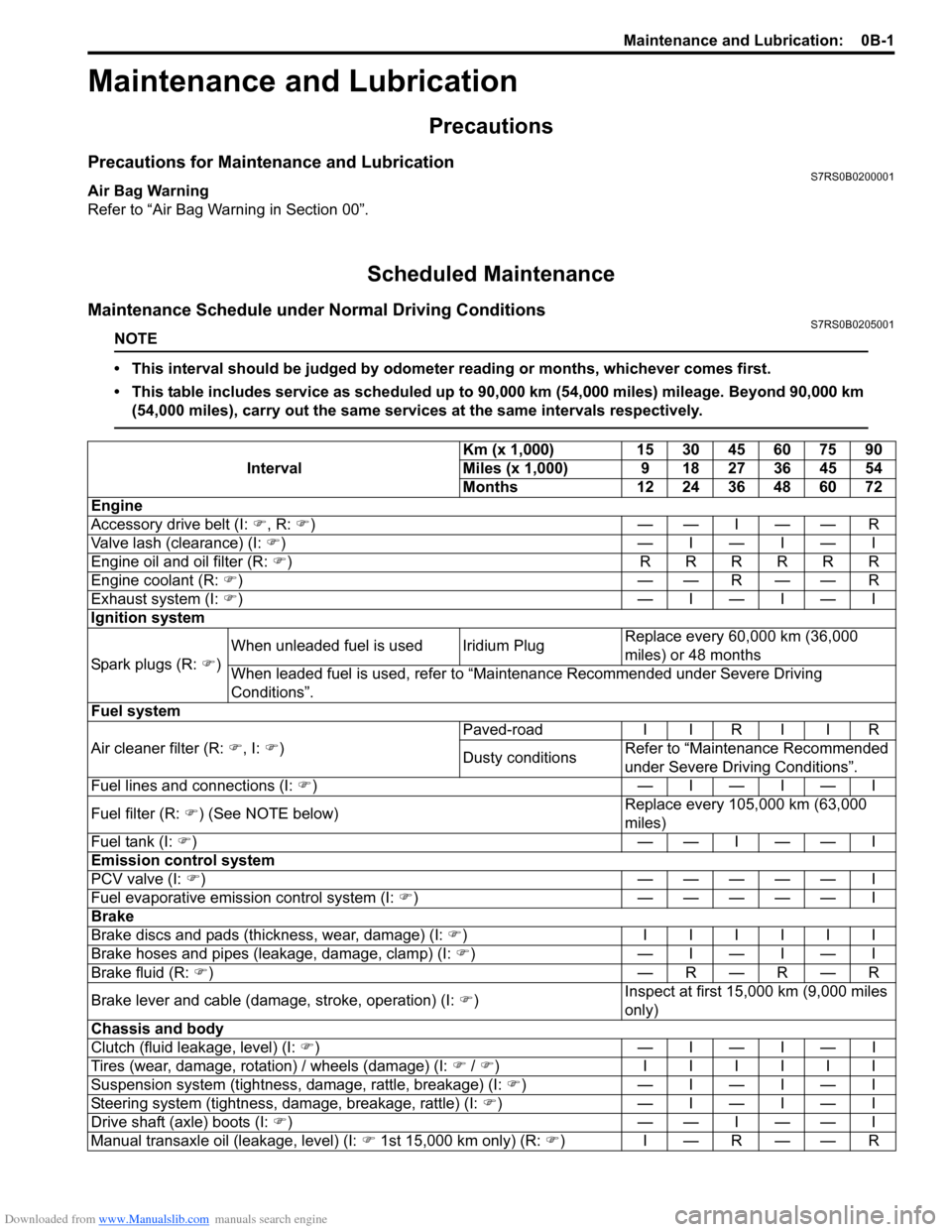
Maintenance Schedule under Normal Driving ConditionsS7RS0B0205001
NOTE
• This interval should be judged by odometer reading or months, whichever comes first.
• This table includes service as scheduled up to 90,000 km (54,000 miles) mileage. Beyond 90,000 km
(54,000 miles), carry out the same services at the same intervals respectively.
Interval Km (x 1,000) 15 30 45 60 75 90
Miles (x 1,000) 9 18 27 36 45 54
Months 12 24 36 48 60 72
Engine
Accessory drive belt (I: �), R: �))——I——R
Valve lash (clearance) (I: �)) —I—I—I
Engine oil and oil filter (R: �)) RRRRRR
Engine coolant (R: �))— —R— — R
Exhaust system (I: �)) —I—I—I
Ignition system
Spark plugs (R: �) )When unleaded fuel is used Iridium Plug
Replace every 60,000 km (36,000
miles) or 48 months
When leaded fuel is used, refer to “Maintenance Recommended under Severe Driving
Conditions”.
Fuel system
Air cleaner filter (R: �), I: �)) Paved-road
I I R I I R
Dusty conditions Refer to “Maintenance Recommended
under Severe Driv
ing Conditions”.
Fuel lines and connections (I: �)) —I—I—I
Fuel filter (R: �)) (See NOTE below) Replace every 105,000 km (63,000
miles)
Fuel tank (I: �))— —I— — I
Emission control system
PCV valve (I: �)) ————— I
Fuel evaporative emission control system (I: �)) ————— I
Brake
Brake discs and pads (thickness, wear, damage) (I: �)) IIIIII
Brake hoses and pipes (leakage, damage, clamp) (I: �)) —I—I—I
Brake fluid (R: �)) —R—R—R
Brake lever and cable (damage, stroke, operation) (I: �)) Inspect at first 15,000 km (9,000 miles
only)
Chassis and body
Clutch (fluid leakage, level) (I: �)) —I—I—I
Tires (wear, damage, rotation) / wheels (damage) (I: �) / �) ) IIIIII
Suspension system (tightness, damage, rattle, breakage) (I: �)) —I—I—I
Steering system (tightness, damage, breakage, rattle) (I: �)) —I—I—I
Drive shaft (axle) boots (I: �))— —I— — I
Manual transaxle oil (leakage, level) (I: �) 1st 15,000 km only) (R: �))I—R——R
Page 37 of 1496
Downloaded from www.Manualslib.com manuals search engine Maintenance and Lubrication: 0B-7
Fuel Filter ReplacementS7RS0B0206011
Fuel filter is installed in fuel pump assembly in fuel tank.
Replace fuel filter or fuel pump assembly with new one,
referring to “Fuel Pump Assembly Removal and
Installation in Section 1G” for proper procedure.
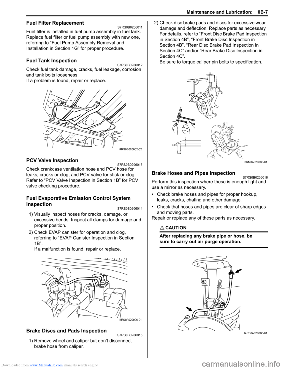
Fuel Tank InspectionS7RS0B0206012
Check fuel tank damage, cracks, fuel leakage, corrosion
and tank bolts looseness.
If a problem is found, repair or replace.
PCV Valve InspectionS7RS0B0206013
Check crankcase ventilation hose and PCV hose for
leaks, cracks or clog, and PCV valve for stick or clog.
Refer to “PCV Valve Inspection in Section 1B” for PCV
valve checking procedure.
Fuel Evaporative Emission Control System
Inspection
S7RS0B0206014
1) Visually inspect hoses for cracks, damage, or excessive bends. Inspect a ll clamps for damage and
proper position.
2) Check EVAP canister for operation and clog, referring to “EVAP Canister Inspection in Section
1B”.
If a malfunction is found, repair or replace.
Brake Discs and Pads InspectionS7RS0B0206015
1) Remove wheel and caliper but don’t disconnect brake hose from caliper. 2) Check disc brake pads and discs for excessive wear,
damage and deflection. Replace parts as necessary.
For details, refer to “Front Disc Brake Pad Inspection
in Section 4B”, “Front Brake Disc Inspection in
Section 4B”, “Rear Disc Brake Pad Inspection in
Section 4C” and/or “Rear Brake Disc Inspection in
Section 4C”.
Be sure to torque caliper pin bolts to specification.
Brake Hoses and Pipes InspectionS7RS0B0206016
Perform this inspection where these is enough light and
use a mirror as necessary.
• Check brake hoses and pipes for proper hookup, leaks, cracks, chafing and other damage.
• Check that hoses and pipes are clear of sharp edges and moving parts.
Repair or replace any of these parts as necessary.
CAUTION!
After replacing any brake pipe or hose, be
sure to carry out air purge operation.
I4RS0B020002-02
I4RS0A020006-01
I3RM0A020006-01
I4RS0A020008-01
Page 48 of 1496

Downloaded from www.Manualslib.com manuals search engine 1-iv Table of Contents
Engine Lubrication System.....................1E-1
General Description ............................................. 1E-1
Engine Lubrication Description ........................... 1E-1
Diagnostic Information and Procedures ............ 1E-2 Oil Pressure Check ............................................. 1E-2
Repair Instructions ........... ................................... 1E-3
Heat Exchanger Components ............................. 1E-3
Heat Exchanger On-Vehicle Inspection .............. 1E-4
Heat Exchanger Removal and Installation .......... 1E-4
Oil Pan and Oil Pump Strainer Components....... 1E-5
Oil Pan and Oil Pump Strainer Removal and
Installation ......................................................... 1E-5
Oil Pan and Oil Pump Stra iner Cleaning ............. 1E-7
Oil Pump Components ........................................ 1E-8
Oil Pump Removal and Installation ..................... 1E-8
Oil Pump Disassembly and Reassembly ............ 1E-8
Oil Pump Inspection ............................................ 1E-9
Specifications .... ................................................. 1E-11
Tightening Torque Specifications ...................... 1E-11
Special Tools and Equipmen t ........................... 1E-11
Recommended Service Material ....................... 1E-11
Special Tool ...................................................... 1E-11
Engine Cooling System ..... ...................... 1F-1
General Description .......... ................................... 1F-1
Cooling System Descriptio n ................................ 1F-1
Coolant Description ............................................. 1F-1
Schematic and Routing Diagram ........................ 1F-2 Coolant Circulation .............................................. 1F-2
Diagnostic Information and Procedures ............ 1F-4 Engine Cooling Symptom Diagnosis ................... 1F-4
Repair Instructions ........... ................................... 1F-5
Cooling System Components.............................. 1F-5
Coolant Level Check ........................................... 1F-6
Engine Cooling System Inspection and Cleaning ............................................................ 1F-6
Cooling System Draining.. ................................... 1F-6
Cooling System Flush and Refill ......................... 1F-7
Cooling Water Pipes or Hoses Removal and Installation ......................................................... 1F-7
Thermostat Removal and In stallation.................. 1F-8
Thermostat Inspection......................................... 1F-8
Radiator Cooling Fan Motor On-Vehicle Inspection .......................................................... 1F-9
Radiator Cooling Fan Rela y Inspection............... 1F-9
Radiator Cooling Fan Removal and Installation ....................................................... 1F-10
Radiator On-Vehicle Inspection and Cleaning .. 1F-10
Radiator Removal and Inst allation .................... 1F-10
Water Pump Removal and In stallation .............. 1F-11
Water Pump Inspection ..................................... 1F-11
Specifications .... ................................................. 1F-12
Tightening Torque Specifications ...................... 1F-12
Special Tools and Equipmen t ........................... 1F-12
Recommended Service Material ....................... 1F-12
Fuel System ................... .......................... 1G-1
Precautions.......................................................... 1G-1 Precautions on Fuel System Service ................. 1G-1
General Description ............................................ 1G-1 Fuel System Description .................................... 1G-1
Fuel Delivery System Description ...................... 1G-1
Fuel Pump Description ....................................... 1G-2
Schematic and Routing Diagram ....................... 1G-2 Fuel Delivery System Diag ram........................... 1G-2
Diagnostic Information and Procedures ........... 1G-2 Fuel Pressure Inspection ................................... 1G-2
Fuel Cut Operation Inspection ........................... 1G-3
Repair Instructions ............ ................................. 1G-4
Fuel System Components .................................. 1G-4
Fuel Hose Disconnecting and Reconnecting ..... 1G-5
Fuel Pressure Relief Procedure ......................... 1G-7
Fuel Leakage Check Procedure......................... 1G-7
Fuel Lines On-Vehicle Inspection ...................... 1G-7
Fuel Pipe Removal and Installation.................... 1G-7
Fuel Injector On-Vehicle Inspection ................... 1G-8
Fuel Injector Removal and Installation ............... 1G-8
Fuel Injector Inspection ...................................... 1G-9
Fuel Filler Cap Inspection . ............................... 1G-10
Fuel Tank Inlet Valve Removal and Installation ...................................................... 1G-11
Fuel Tank Inlet Valve Inspection ...................... 1G-12
Fuel Tank Removal and Installation ................. 1G-12
Fuel Tank Inspection ........................................ 1G-13
Fuel Tank Purging Procedure .......................... 1G-14
Fuel Pump On-Vehicle Inspection.................... 1G-14
Fuel Pump Assembly Removal and Installation ...................................................... 1G-14
Main Fuel Level Sensor Removal and Installation ...................................................... 1G-15
Fuel Pump Inspection ...................................... 1G-16
Specifications ..................... ............................... 1G-16
Tightening Torque Specifications ..................... 1G-16
Special Tools and Equipmen t .......................... 1G-17
Special Tool ..................................................... 1G-17
Ignition System .............. .......................... 1H-1
General Description .............................................1H-1
Ignition System Construction ..............................1H-1
Schematic and Routing Diagram ........................1H-2 Ignition System Wiring Circuit Diagram...............1H-2
Component Location ............ ...............................1H-3
Ignition System Components Location................1H-3
Diagnostic Information and Procedures ............1H-4 Ignition System Symptom Diagnosis...................1H-4
Reference Waveform of Ignition System.............1H-4
Ignition System Check ........................................1H-4
Ignition Spark Test ..............................................1H-6
Repair Instructions ............ ..................................1H-6
High-Tension Cord Removal and Installation......1H-6
High-Tension Cord Inspection.............................1H-7
Spark Plug Removal and Installation ..................1H-7
Spark Plug Inspection .........................................1H-7
Ignition Coil Assembly (Including ignitor)
Removal and Installation ...................................1H-8
Ignition Coil Assembly (Including ignitor)
Inspection ..........................................................1H-8
Page 56 of 1496
Downloaded from www.Manualslib.com manuals search engine 1A-6 Engine General Information and Diagnosis:
For information about the following items, refer to “Euro
OBD Model: ”.
• Warm-up cycle
• Driving cycle
• 2 driving cycle detection logic
• Pending DTC
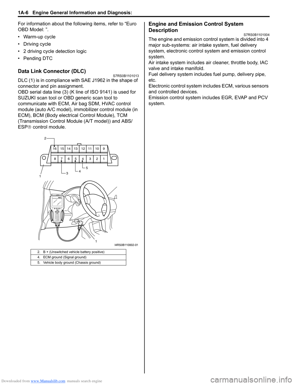
Data Link Connector (DLC)S7RS0B1101013
DLC (1) is in compliance with SAE J1962 in the shape of
connector and pin assignment.
OBD serial data line (3) (K line of ISO 9141) is used for
SUZUKI scan tool or OBD generic scan tool to
communicate with ECM, Air bag SDM, HVAC control
module (auto A/C model), immobilizer control module (in
ECM), BCM (Body electrical Control Module), TCM
(Transmission Cont rol Module (A/T model)) and ABS/
ESP ® control module.
Engine and Emission Control System
Description
S7RS0B1101004
The engine and emission control system is divided into 4
major sub-systems: air in take system, fuel delivery
system, electronic control sy stem and emission control
system.
Air intake system includes air cleaner, throttle body, IAC
valve and intake manifold.
Fuel delivery system includes fuel pump, delivery pipe,
etc.
Electronic control system incl udes ECM, various sensors
and controlled devices.
Emission control system includes EGR, EVAP and PCV
system.
2. B + (Unswitched vehicle battery positive)
4. ECM ground (Signal ground)
5. Vehicle body ground (Chassis ground)
2
345
1
910111213141516
12345678
1I4RS0B110002-01
Page 63 of 1496
Downloaded from www.Manualslib.com manuals search engine Engine General Information and Diagnosis: 1A-13
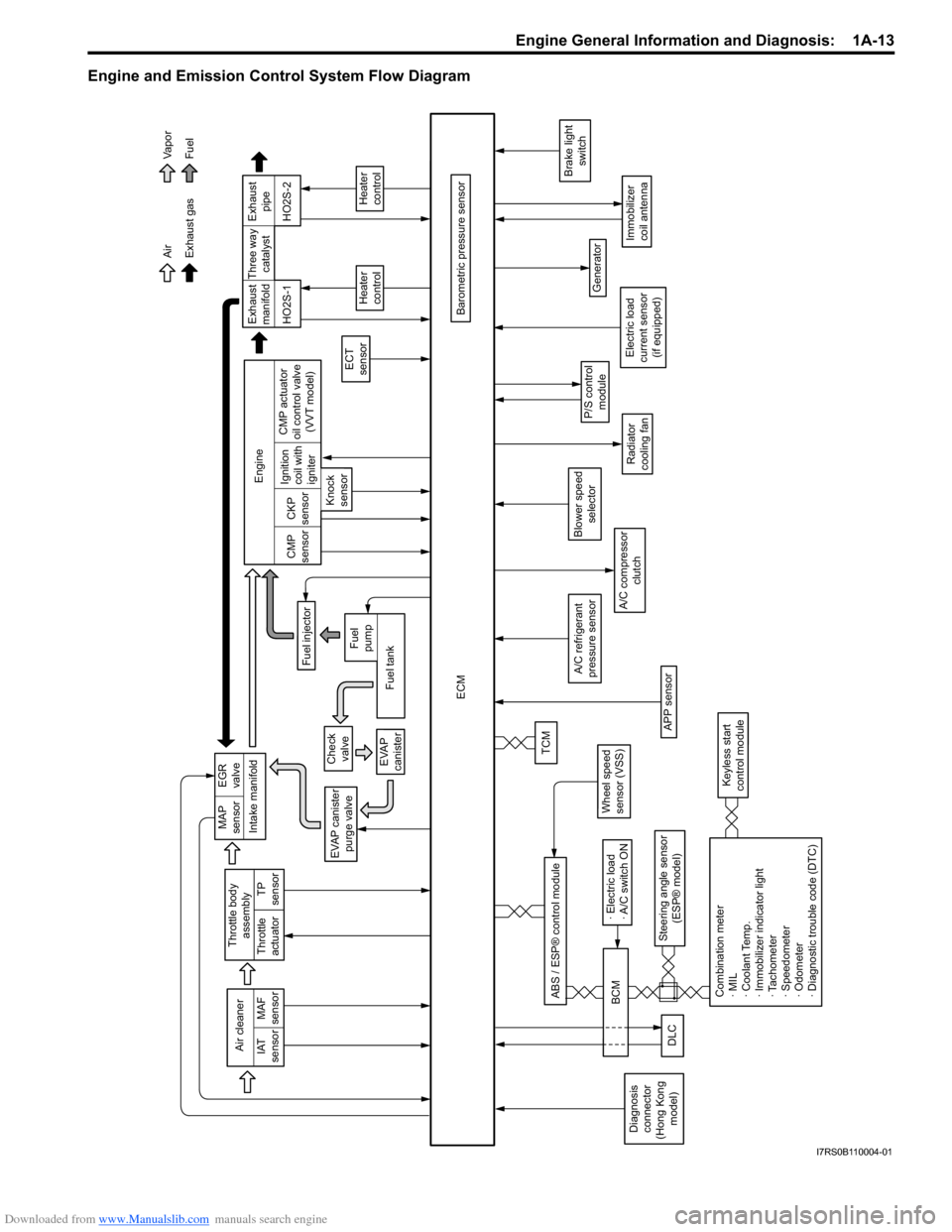
Engine and Emission Control System Flow Diagram
Intake manifold
Exhaust gas AirFuel
Va p o r
EVAP canister purge valve
ECM
Barometric pressure sensor
A/C compressor clutch
Generator
Immobilizer
coil antenna
P/S controlmodule
Brake light switch
Air cleaner
IAT
sensor MAF
sensor
A/C refrigerant
pressure sensor
TP
sensor
Throttle body
assembly
Throttle
actuator
Wheel speed
sensor (VSS)
Steering angle sensor (ESP® model)
ABS / ESP® control module
Blower speed
selector
MAP
sensor EGR
valve
Check valve
EVAP
canisterTCM
Exhaust
manifold Exhaust
pipe
Fuel injector
ECT
sensor
Heater
control
HO2S-1 HO2S-2
Engine
CMP
sensor CKP
sensor
Knock
sensor Ignition
coil with
igniter
Fuel tank
Fuel
pump CMP actuator
oil control valve (VVT model) Three way
catalyst
Heater
control
Radiator
cooling fan
Combination meter
· MIL
· Coolant Temp.
· Immobilizer indicator light
· Tachometer
· Speedometer
· Odometer
· Diagnostic trouble code (DTC)
Keyless start
control module
DLC
· Electric load
· A/C switch ON
BCM
Diagnosis
connector
(Hong Kong model) Electric load
current sensor (if equipped)
APP sensor
I7RS0B110004-01