2005 SUZUKI SWIFT reverse
[x] Cancel search: reversePage 946 of 1496
Downloaded from www.Manualslib.com manuals search engine 7A-10 Heater and Ventilation:
Air Intake Control Actuator InspectionS7RS0B7106013
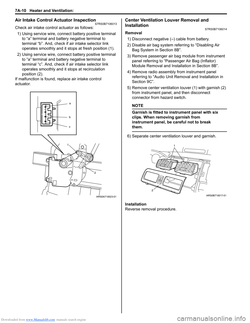
Check air intake control actuator as follows:1) Using service wire, connect battery positive terminal to “a” terminal and battery negative terminal to
terminal “b”. And, check if air intake selector link
operates smoothly and it st ops at fresh position (1).
2) Using service wire, connect battery positive terminal to “a” terminal and battery negative terminal to
terminal “c”. And, check if air intake selector link
operates smoothly and it stops at recirculation
position (2).
If malfunction is found, replace air intake control
actuator.
Center Ventilation Louver Removal and
Installation
S7RS0B7106014
Removal
1) Disconnect negative (–) cable from battery.
2) Disable air bag system referring to “Disabling Air Bag System in Section 8B”.
3) Remove passenger air bag module from instrument panel referring to “Passenger Air Bag (Inflator)
Module Removal and Installation in Section 8B”.
4) Remove radio assembly from instrument panel referring to “Audio Unit Re moval and Installation in
Section 9C”.
5) Remove center ventilation louver (1) with garnish (2) from instrument panel, and then disconnect
connector from hazard switch.
NOTE
Garnish is fitted to in strument panel with six
clips. When removing garnish from
instrument panel, be careful not to break
them.
6) Separate center ventilation louver and garnish.
Installation
Reverse removal procedure.
a
b
c
1
2
I4RS0A710023-01
1
2
I4RS0B710017-01
Page 947 of 1496
Downloaded from www.Manualslib.com manuals search engine Heater and Ventilation: 7A-11
Side Ventilation Louver Removal and
Installation
S7RS0B7106015
Driver side ventilation louver
Removal1) Disconnect negative (–) cable from battery.
2) Disable air bag system referring to “Disabling Air Bag System in Section 8B”.
3) Remove steering column hol e cover from instrument
panel.
4) Remove combination meter cluster panel from instrument panel, and then disconnect connectors
from front fog lamp switch, illumination cancel switch
and headlight leveling switch (if equipped) of
combination meter cluster panel.
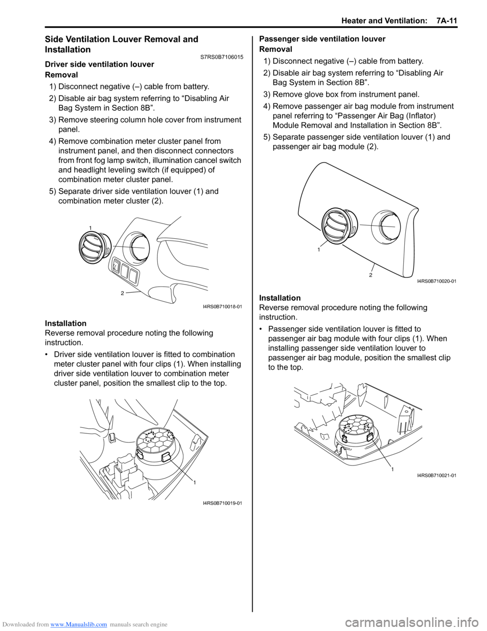
5) Separate driver side ventilation louver (1) and combination meter cluster (2).
Installation
Reverse removal procedure noting the following
instruction.
• Driver side ventilation louver is fitted to combination meter cluster panel with four clips (1). When installing
driver side ventilation louv er to combination meter
cluster panel, position the smallest clip to the top. Passenger side ventilation louver
Removal
1) Disconnect negative (–) cable from battery.
2) Disable air bag system referring to “Disabling Air Bag System in Section 8B”.
3) Remove glove box from instrument panel.
4) Remove passenger air bag module from instrument panel referring to “Passenger Air Bag (Inflator)
Module Removal and Installation in Section 8B”.
5) Separate passenger side ventilation louver (1) and passenger air bag module (2).
Installation
Reverse removal procedure noting the following
instruction.
• Passenger side ventilation louver is fitted to passenger air bag module with four clips (1). When
installing passenger side ventilation louver to
passenger air bag module, position the smallest clip
to the top.
2
1
I4RS0B710018-01
1
I4RS0B710019-01
2
1
I4RS0B710020-01
1I4RS0B710021-01
Page 948 of 1496
Downloaded from www.Manualslib.com manuals search engine 7A-12 Heater and Ventilation:
HVAC Air Filter Removal and Installation (If
Equipped)
S7RS0B7106016
Removal1) Remove glove box from instrument panel.
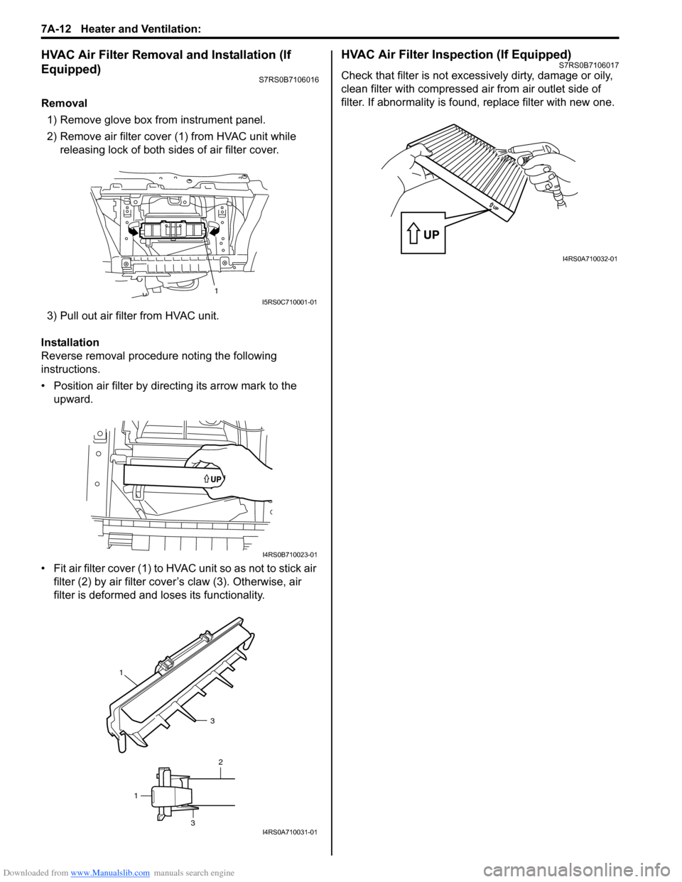
2) Remove air filter cover (1) from HVAC unit while
releasing lock of both sides of air filter cover.
3) Pull out air filter from HVAC unit.
Installation
Reverse removal procedure noting the following
instructions.
• Position air filter by directing its arrow mark to the upward.
• Fit air filter cover (1) to HVAC unit so as not to stick air
filter (2) by air filter cove r’s claw (3). Otherwise, air
filter is deformed and loses its functionality.
HVAC Air Filter Inspection (If Equipped)S7RS0B7106017
Check that filter is not excessively dirty, damage or oily,
clean filter with compressed air from air outlet side of
filter. If abnormality is found, replace filter with new one.
1I5RS0C710001-01
I4RS0B710023-01
1
3
2
1
3I4RS0A710031-01
I4RS0A710032-01
Page 958 of 1496

Downloaded from www.Manualslib.com manuals search engine 7B-10 Air Conditioning System: Manual Type
Abnormal Noise from Tension Pulley
Abnormal Noise from A/C Evaporator
Abnormal Noise from Blower Motor
A/C System Performance InspectionS7RS0B7214003
1) Confirm that vehicle and environmental conditions are as follows.
• Vehicle is put indoors.
• Ambient temperature is within 25 – 35 °C (77 – 95
° F).
• Relative humidity is within 30 – 70%.
• There is no wind indoors.
• HVAC unit is normal.
• Blower motor is normal.
• There is no air leakage from air ducts.
• Condenser fins are clean.
• Air filter in HVAC unit is not clogged with dirt and
dust.
• Battery voltage is about 12 V.
• Radiator cooling fan operates normally.
2) Make sure that high pressure valve (1) and low pressure valve (2) of manifold gauge are firmly
closed.
3) Connect high pressure charging hose (3) to high pressure service valve (5) on vehicle and low
pressure charging hose (4) to low pressure service
valve (6).
4) Bleed the air in charging hoses (3) and (4) by loosening their nuts respectively utilizing the
refrigerant pressure. When a hissing sound is heard,
immediately tighten nut.
CAUTION!
Do not connect high and low pressure
charging hoses in reverse.
Condition Possible cause Correction / Reference Item
Clattering noise is heard
from pulley Worn or damaged bearing
Replace tension pulley.
Pulley cranks upon
contact Cracked or loose bracket
Replace or retighten bracket.
ConditionPossible cause Correction / Reference Item
Whistling sound is heard
from A/C evaporator Depending on the combination of the
interior / exterior temperatures, engine
rpm and refrigerant pressure, the
refrigerant flowing out of the expansion
valve may, under certain conditions,
make a whistling sound At times, slightly decrea
sing refrigerant volume
may stop this noise.
Inspect expansion valve and replace if faulty.
Condition Possible cause Correction / Reference Item
Blower motor emits a
chirping sound in
proportion to its speed of
rotation Worn or damaged motor brushes or
commutator
Replace blower motor.
Fluttering noise or large
droning noise is heard
from blower motor Leaves or other debris introduced from
fresh air inlet to blower motor
Remove debris and make sure that the screen
at fresh air inlet is intact.
53
2
1
4 6
I4RS0A720006-01
Page 967 of 1496
Downloaded from www.Manualslib.com manuals search engine Air Conditioning System: Manual Type 7B-19
Charge
CAUTION!
• Because the sight glass is not used for this A/C system, do not perform an additional
charge to the A/C system. To charge the
proper amount of refrigerant, recover and
evacuate the A/C system first. And then,
charge the proper amount of refrigerant
into the A/C system.
• Always charge refrigerant through low pressure side of A/C system after the initial
charge is performed from the high
pressure side with the engine stopped.
• Never charge refrigerant through high pressure side of A/C system with engine
running.
• Do not charge refrigerant while compressor is hot.
• When installing tap valve to refrigerant container to make a hole there through,
carefully follow dire ctions given by
manufacturer.
• A pressure gauge should always be used before and during refrigerant charge.
• The refrigerant container should be emptied of refrigerant when discarding it.
• The refrigerant container should not be heated up to 40 °C (104 °F) or over.
• Refrigerant container should not be reversed in direction during refrigerant
charge. Reversing in direction causes
liquid refrigerant to enter compressor,
causing troubles, such as compression of
liquid refrigerant and the like.
NOTE
The air conditioning system contains HFC-
134a (R-134a).
Described here is a method to charge the air
conditioning system with refrigerant from the
refrigerant service container.
When charging refrigerant recovered by
using the refrigerant and recycling
equipment (when recycling refrigerant),
follow the procedure described in the
equipment manufacturer’s instruction
manual.
Charge proper amount of refrigerant accurately in
accordance with the following procedure.
Specified amount of refrigerant
370 ± 20 g (13.0 ± 0.7 oz)
The initial charge of the A/C system is performed
through the high pressure side with the engine stopped.
And next, this method must be followed by charging from
the low pressure side with the engine running.
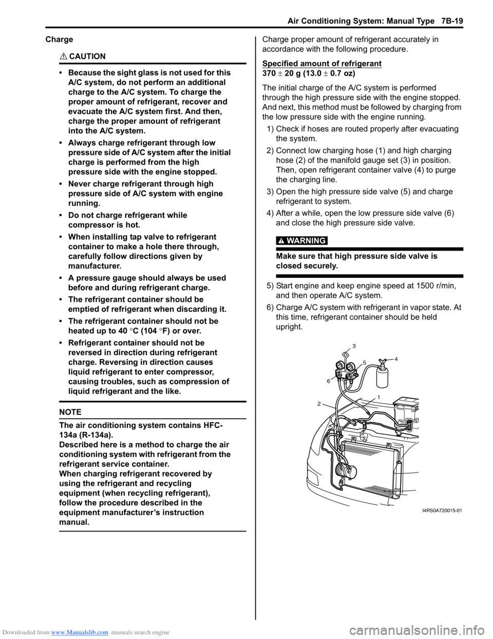
1) Check if hoses are routed properly after evacuating the system.
2) Connect low charging hose (1) and high charging hose (2) of the manifold gauge set (3) in position.
Then, open refrigerant container valve (4) to purge
the charging line.
3) Open the high pressure side valve (5) and charge refrigerant to system.
4) After a while, open the low pressure side valve (6) and close the high pressure side valve.
WARNING!
Make sure that high pressure side valve is
closed securely.
5) Start engine and keep engine speed at 1500 r/min, and then operate A/C system.
6) Charge A/C system with refrigerant in vapor state. At this time, refrigerant container should be held
upright.
1
2 6 3
5 4
I4RS0A720015-01
Page 970 of 1496
Downloaded from www.Manualslib.com manuals search engine 7B-22 Air Conditioning System: Manual Type
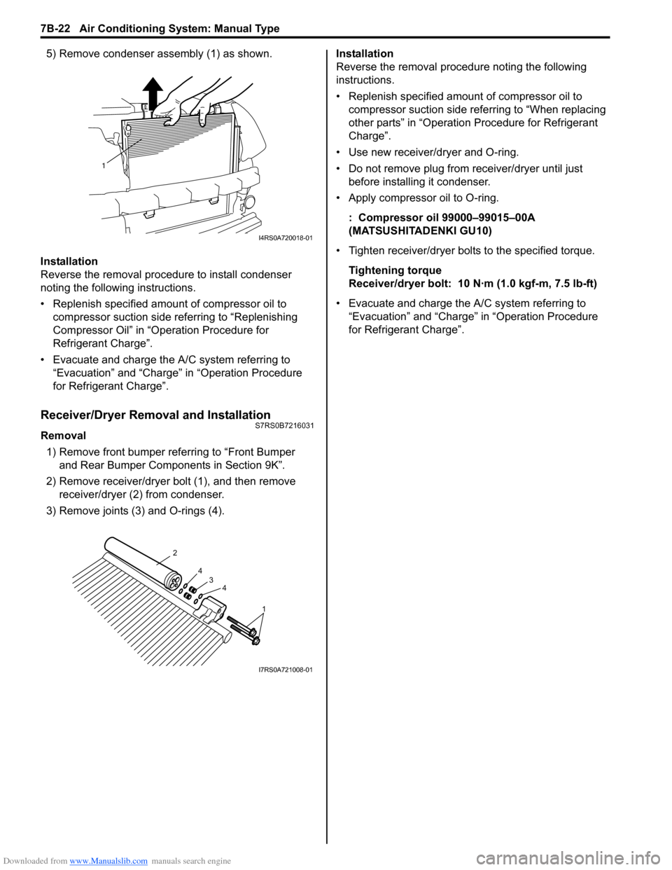
5) Remove condenser assembly (1) as shown.
Installation
Reverse the removal procedure to install condenser
noting the following instructions.
• Replenish specified amount of compressor oil to compressor suction side referring to “Replenishing
Compressor Oil” in “Operation Procedure for
Refrigerant Charge”.
• Evacuate and charge the A/C system referring to “Evacuation” and “Charge” in “Operation Procedure
for Refrigerant Charge”.
Receiver/Dryer Removal and InstallationS7RS0B7216031
Removal
1) Remove front bumper referring to “Front Bumper and Rear Bumper Components in Section 9K”.
2) Remove receiver/dryer bolt (1), and then remove receiver/dryer (2) from condenser.
3) Remove joints (3) and O-rings (4). Installation
Reverse the removal procedure noting the following
instructions.
• Replenish specified amount of compressor oil to
compressor suction side referring to “When replacing
other parts” in “Operation Procedure for Refrigerant
Charge”.
• Use new receiver/dryer and O-ring.
• Do not remove plug from receiver/dryer until just before installin g it condenser.
• Apply compressor oil to O-ring.
: Compressor oil 99000–99015–00A
(MATSUSHITADENKI GU10)
• Tighten receiver/dryer bolts to the specified torque. Tightening torque
Receiver/dryer bolt: 10 N· m (1.0 kgf-m, 7.5 lb-ft)
• Evacuate and charge the A/C system referring to “Evacuation” and “Charge” in “Operation Procedure
for Refrigerant Charge”.
1
I4RS0A720018-01
1
4
4
3
2
I7RS0A721008-01
Page 972 of 1496

Downloaded from www.Manualslib.com manuals search engine 7B-24 Air Conditioning System: Manual Type
HVAC Unit Removal and InstallationS7RS0B7216006
Removal1) Disconnect negative (–) cable from battery.
2) Disable air bag system referring to “Disabling Air Bag System in Section 8B”.
3) Recover refrigerant from A/C system with recovery and recycling equipment referring to “Recovery” in
“Operation Procedure for Refrigerant Charge”.
4) Remove cowl top panel referring to “Cowl Top Components in Section 9K”.
5) Drain engine coolant, and then disconnect heater hoses (1) from HVAC unit (2).
6) Remove instrument panel from vehicle body referring to “Audio Unit Re moval and Installation in
Section 9C”.
7) Loosen suction hose and liquid pipe bolt (4).
8) Remove nuts (3).
9) Remove HVAC unit from vehicle body. Installation
Reverse removal procedure noting the following
instructions.
• Replenish specified amount of compressor oil to
compressor suction side referring to “Replenishing
Compressor Oil” in “Operation Procedure for
Refrigerant Charge”.
• Install the padding (1) to the installation hole uniformly.
• Evacuate and charge the A/C system referring to “Evacuation” and “Charge” in “Operation Procedure
for Refrigerant Charge”.
• Adjust control cables referr ing to “HVAC Control Unit
Removal and Installati on in Section 7A”.
• Enable air bag system referring to “Enabling Air Bag System in Section 8B”.
Evaporator InspectionS7RS0B7216007
Check the followings.
• Clog of A/C evaporator fins.If any clogs are found, A/C evaporator fins should be
washed with water, and then should be dried with
compressed air.
• A/C evaporator fins for leakage and breakage. If any defects are found, repair or replace A/C
evaporator.
• A/C evaporator fittings for leakage. If any defects are found, repair or replace A/C
evaporator.
2. Blower upper case 8. Temperature control door assembly 14. Temperature control lever 20. Packing
3. Air intake control actuator 9. Blower motor resistor 15. Airflow control lever21. Filter cover (if equipped)
4. HVAC Air filter (if equipped) 10. Blower lower case 16. Evaporator22. Drain hose
5. Heater unit upper case 11. Blower motor 17. O-ring23. Cable lock clamp
6. Foot duct 12. Heater unit lower case 18. Expansion valve: Do not reuse.
3
2
3
3
1
4
I4RS0B720009-01
1
I4RS0B720010-01
Page 973 of 1496
Downloaded from www.Manualslib.com manuals search engine Air Conditioning System: Manual Type 7B-25
Evaporator Thermistor (Evaporator
Temperature Sensor) Removal and Installation
S7RS0B7216008
Removal1) Disconnect negative (–) cable from battery.
2) Remove HVAC unit from vehicle body referring to “HVAC Unit Removal and Installation”.
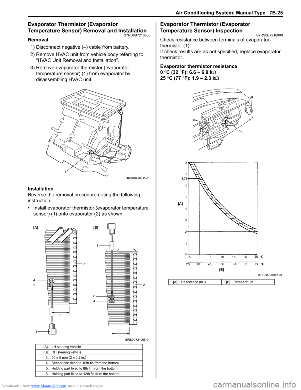
3) Remove evaporator thermistor (evaporator temperature sensor) (1) from evaporator by
disassembling HVAC unit.
Installation
Reverse the removal procedure noting the following
instruction.
• Install evaporator thermistor (evaporator temperature sensor) (1) onto evaporator (2) as shown.
Evaporator Thermistor (Evaporator
Temperature Sensor) Inspection
S7RS0B7216009
Check resistance between terminals of evaporator
thermistor (1).
If check results are as not specified, replace evaporator
thermistor.
Evaporator thermistor resistance
0 °C (32 °F): 6.6 – 6.9 k Ω
25 °C (77 °F): 1.9 – 2.3 kΩ
[A]: LH steering vehicle
[B]: RH steering vehicle
3. 50 ± 5 mm (2 ± 0.2 in.)
4. Sensor part fixed to 10th fin from the bottom
5. Holding part fixed to 8th fin from the bottom
6. Holding part fixed to 12th fin from the bottom
1
I4RS0B720011-01
5
1
4
2
3
[A]
1
4 2
3
6 [B]
I5RS0C721008-01
[A]: Resistance (k Ω) [B]: Temperature
I4RS0B720012-01