2005 SUZUKI SWIFT reverse
[x] Cancel search: reversePage 855 of 1496
Downloaded from www.Manualslib.com manuals search engine Clutch: 5C-3
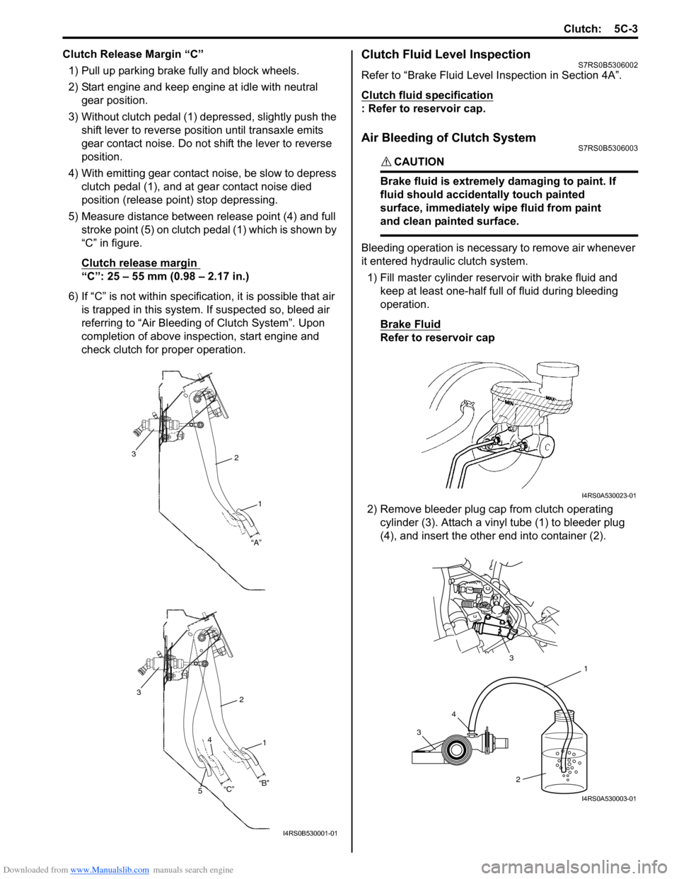
Clutch Release Margin “C”1) Pull up parking brake fully and block wheels.
2) Start engine and keep engine at idle with neutral gear position.
3) Without clutch pedal (1) dep ressed, slightly push the
shift lever to re verse position until transaxle emits
gear contact noise. Do not shift the lever to reverse
position.
4) With emitting gear contact noise, be slow to depress clutch pedal (1), and at gear contact noise died
position (release point) stop depressing.
5) Measure distance between release point (4) and full stroke point (5) on clutch pedal (1) which is shown by
“C” in figure.
Clutch release margin
“C”: 25 – 55 mm (0.98 – 2.17 in.)
6) If “C” is not within specificat ion, it is possible that air
is trapped in this system. If suspected so, bleed air
referring to “Air Bleeding of Clutch System”. Upon
completion of above inspection, start engine and
check clutch for proper operation.
Clutch Fluid Level InspectionS7RS0B5306002
Refer to “Brake Fluid Level Inspection in Section 4A”.
Clutch fluid specification
: Refer to reservoir cap.
Air Bleeding of Clutch SystemS7RS0B5306003
CAUTION!
Brake fluid is extremely damaging to paint. If
fluid should accidentally touch painted
surface, immediately wipe fluid from paint
and clean painted surface.
Bleeding operation is necessary to remove air whenever
it entered hydraulic clutch system.
1) Fill master cylinder reservoir with brake fluid and keep at least one-half full of fluid during bleeding
operation.
Brake Fluid
Refer to reservoir cap
2) Remove bleeder plug cap from clutch operating cylinder (3). Attach a vinyl tube (1) to bleeder plug
(4), and insert the other end into container (2).
2
1
“A”
3
2
1
3
“B”
“C”
4
5
I4RS0B530001-01
I4RS0A530023-01
3 4 1
2
3
I4RS0A530003-01
Page 858 of 1496
Downloaded from www.Manualslib.com manuals search engine 5C-6 Clutch:
Clutch Fluid Pipe Removal and InstallationS7RS0B5306007
Removal
CAUTION!
Do not allow fluid to get on painted surface. It
may cause painted surface damage.
1) Remove dust and dirt from each joint of pipe to be disconnected and clean around brake master
cylinder reservoir cap.
2) Take out fluid with syringe or such from brake master cylinder reservoir.
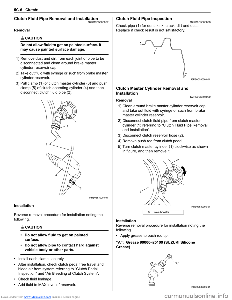
3) Pull clamp (1) of clutch master cylinder (3) and push clamp (5) of clutch operating cylinder (4) and then
disconnect clutch fluid pipe (2).
Installation
Reverse removal procedure for installation noting the
following.
CAUTION!
• Do not allow fluid to get on painted surface.
• Do not allow pipe to contact hard against vehicle body or other parts.
• Install each clamp securely.
• After installation, check clutch pedal free travel and bleed air from system referring to “Clutch Pedal
Inspection” and “Air Blee ding of Clutch System”.
• Check fluid leakage.
• Add fluid to MAX level of reservoir.
Clutch Fluid Pipe InspectionS7RS0B5306008
Check pipe (1) for dent, kink, crack, dirt and dust.
Replace if check result is not satisfactory.
Clutch Master Cylinder Removal and
Installation
S7RS0B5306009
Removal 1) Clean around brake master cylinder reservoir cap and take out fluid with syringe or such from brake
master cylinder reservoir.
2) Disconnect clutch fluid pipe from clutch master cylinder (1) referring to “C lutch Fluid Pipe Removal
and Installation”.
3) Disconnect clutch reservoir hose (2).
4) Remove push rod from clutch pedal.
5) Turn clutch master cylinder (1) clockwise as shown in figure, and then remove it.
Installation
Reverse removal procedure for installation noting the
following.
• Apply grease to push rod tip.
“A”: Grease 99000–25100 (SUZUKI Silicone
Grease)
31
2
5
4
I4RS0B530003-01
3. Brake booster
1
I6RS0C530004-01
1
2
3
I4RS0B530005-01
“A”
I4RS0B530006-01
Page 859 of 1496
Downloaded from www.Manualslib.com manuals search engine Clutch: 5C-7
Clutch Operating Cylinder Removal and
Installation
S7RS0B5306010
Removal1) Clean around brake master cylinder reservoir cap and take out fluid with syringe or such from brake
master cylinder reservoir.
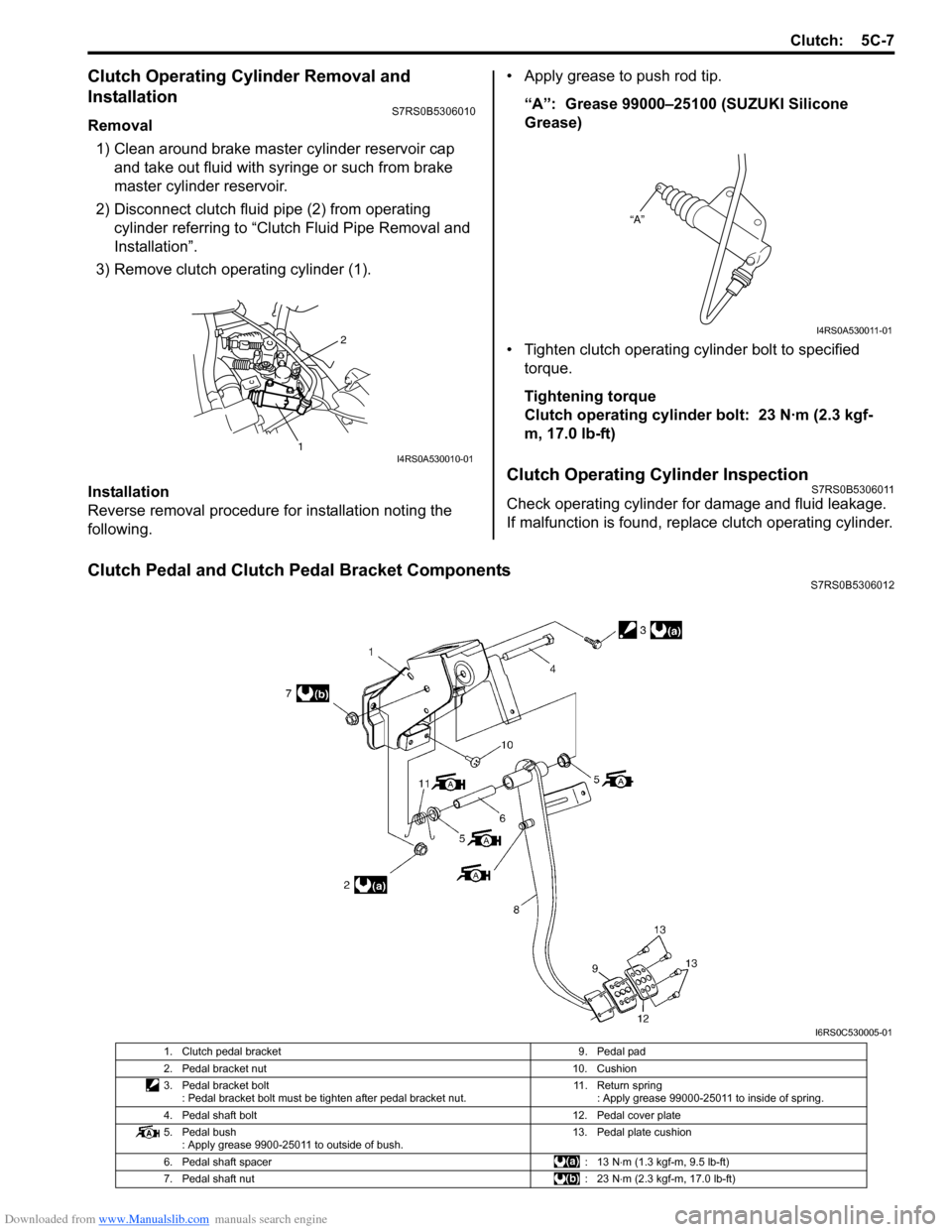
2) Disconnect clutch fluid pipe (2) from operating cylinder referring to “Clutch Fluid Pipe Removal and
Installation”.
3) Remove clutch operating cylinder (1).
Installation
Reverse removal procedure for installation noting the
following. • Apply grease to push rod tip.
“A”: Grease 99000–25100 (SUZUKI Silicone
Grease)
• Tighten clutch operating cylinder bolt to specified torque.
Tightening torque
Clutch operating cylinder bolt: 23 N·m (2.3 kgf-
m, 17.0 lb-ft)
Clutch Operating Cylinder InspectionS7RS0B5306011
Check operating cylinder for damage and fluid leakage.
If malfunction is found, repl ace clutch operating cylinder.
Clutch Pedal and Clutch Pedal Bracket ComponentsS7RS0B5306012
2
1I4RS0A530010-01
“A”
I4RS0A530011-01
I6RS0C530005-01
1. Clutch pedal bracket 9. Pedal pad
2. Pedal bracket nut 10. Cushion
3. Pedal bracket bolt : Pedal bracket bolt must be tighten after pedal bracket nut. 11. Return spring
: Apply grease 99000-25011 to inside of spring.
4. Pedal shaft bolt 12. Pedal cover plate
5. Pedal bush : Apply grease 9900-25011 to outside of bush. 13. Pedal plate cushion
6. Pedal shaft spacer : 13 N⋅m (1.3 kgf-m, 9.5 lb-ft)
7. Pedal shaft nut : 23 N⋅m (2.3 kgf-m, 17.0 lb-ft)
Page 928 of 1496
Downloaded from www.Manualslib.com manuals search engine 6C-46 Power Assisted Steering System:
P/S Control Module Removal and InstallationS7RS0B6306011
Removal1) Disconnect negative cable at battery.
2) Remove console box.
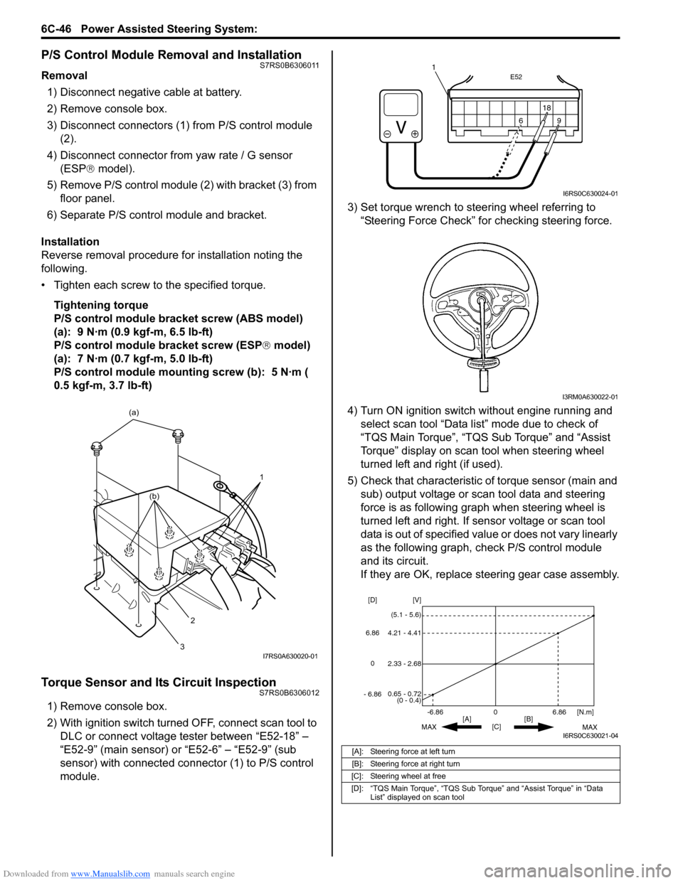
3) Disconnect connectors (1) from P/S control module (2).
4) Disconnect connector from yaw rate / G sensor
(ESP ® model).
5) Remove P/S control module (2) with bracket (3) from floor panel.
6) Separate P/S control module and bracket.
Installation
Reverse removal procedure for installation noting the
following.
• Tighten each screw to the specified torque. Tightening torque
P/S control module bracket screw (ABS model)
(a): 9 N·m (0.9 kgf-m, 6.5 lb-ft)
P/S control module bracket screw (ESP ® model)
(a): 7 N·m (0.7 kgf-m, 5.0 lb-ft)
P/S control module mounting screw (b): 5 N·m (
0.5 kgf-m, 3.7 lb-ft)
Torque Sensor and Its Circuit InspectionS7RS0B6306012
1) Remove console box.
2) With ignition switch turned OFF, connect scan tool to DLC or connect voltage tester between “E52-18” –
“E52-9” (main sensor) or “E52-6” – “E52-9” (sub
sensor) with connected connector (1) to P/S control
module. 3) Set torque wrench to stee
ring wheel referring to
“Steering Force Check” for checking steering force.
4) Turn ON ignition switch without engine running and select scan tool “Data list” mode due to check of
“TQS Main Torque”, “TQS Sub Torque” and “Assist
Torque” display on scan tool when steering wheel
turned left and right (if used).
5) Check that characteristic of torque sensor (main and sub) output voltage or scan tool data and steering
force is as following graph when steering wheel is
turned left and right. If sensor voltage or scan tool
data is out of specified value or does not vary linearly
as the following graph, check P/S control module
and its circuit.
If they are OK, replace steering gear case assembly.
1
(a)
2
3
(b)
I7RS0A630020-01
[A]: Steering force at left turn
[B]: Steering force at right turn
[C]: Steering wheel at free
[D]: “TQS Main Torque”, “TQS Sub Torque” and “Assist Torque” in “Data List” displayed on scan tool
E52
18
9
6
9
6 18
1
I6RS0C630024-01
I3RM0A630022-01
0
[C] [N.m]
MAX MAX
[B]
[A]
2.33 - 2.68 [V]
[D]
0.65 - 0.72
(0 - 0.4)
4.21 - 4.41
(5.1 - 5.6)
6.86
-6.86
0
6.86
- 6.86
I6RS0C630021-04
Page 940 of 1496
Downloaded from www.Manualslib.com manuals search engine 7A-4 Heater and Ventilation:
Repair Instructions
HVAC Unit ComponentsS7RS0B7106001
For manual type A/C, refer to “HVAC Unit Components
in Section 7B”.
For automatic type A/C, refer to “HVAC Unit
Components in Section 7B”.
HVAC Unit Removal and InstallationS7RS0B7106002
Removal
1) Disconnect negative (–) cable from battery.
2) Disable air bag system referring to “Disabling Air Bag System in Section 8B”.
3) Remove cowl top panel from vehicle body referring to “Cowl Top Components in Section 9K”.
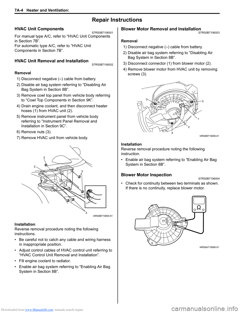
4) Drain engine coolant, and then disconnect heater hoses (1) from HVAC unit (2).
5) Remove instrument panel from vehicle body referring to “Instrument Panel Removal and
Installation in Section 9C”.
6) Remove nuts (3).
7) Remove HVAC unit from vehicle body.
Installation
Reverse removal procedure noting the following
instructions.
• Be careful not to catch any cable and wiring harness in inappropriate position.
• Adjust control cables of HVAC control unit referring to “HVAC Control Unit Remo val and Installation”.
• Fill engine coolant to radiator.
• Enable air bag system referring to “Enabling Air Bag System in Section 8B”.
Blower Motor Removal and InstallationS7RS0B7106003
Removal
1) Disconnect negative (–) cable from battery.
2) Disable air bag system referring to “Disabling Air Bag System in Section 8B”.
3) Disconnect connector (1) from blower motor (2).
4) Remove blower motor from HVAC unit by removing screws (3).
Installation
Reverse removal procedure noting the following
instruction.
• Enable air bag system referring to “Enabling Air Bag System in Section 8B”.
Blower Motor InspectionS7RS0B7106004
• Check for continuity between two terminals as shown. If there is no continuity, replace blower motor.
3
2
3
1
3I4RS0B710004-01
3
1
2
3
3
I4RS0B710005-01
I4RS0A710006-01
Page 941 of 1496
Downloaded from www.Manualslib.com manuals search engine Heater and Ventilation: 7A-5
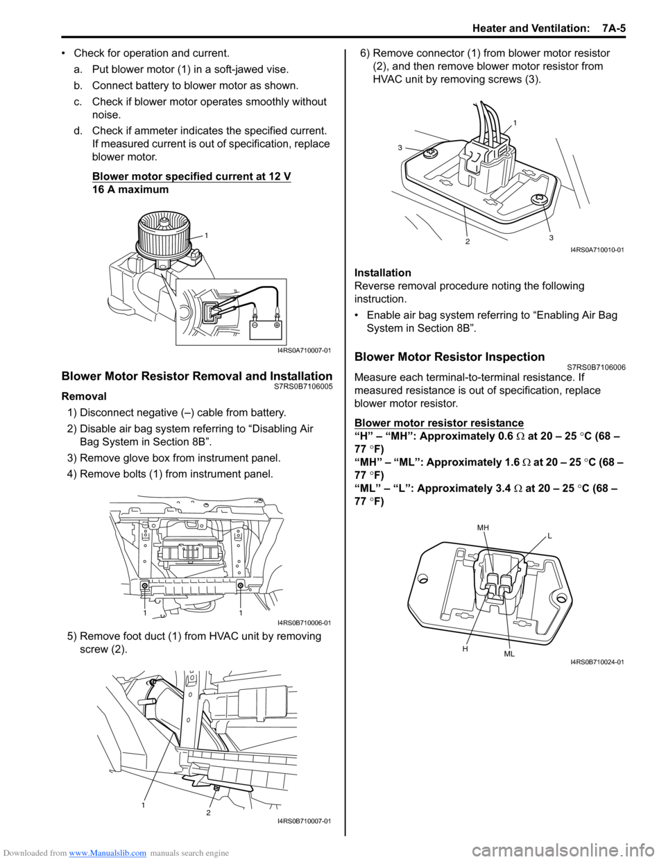
• Check for operation and current.a. Put blower motor (1) in a soft-jawed vise.
b. Connect battery to blower motor as shown.
c. Check if blower motor operates smoothly without noise.
d. Check if ammeter indicates the specified current. If measured current is out of specification, replace
blower motor.
Blower motor specified current at 12 V
16 A maximum
Blower Motor Resistor Removal and InstallationS7RS0B7106005
Removal
1) Disconnect negative (–) cable from battery.
2) Disable air bag system referring to “Disabling Air Bag System in Section 8B”.
3) Remove glove box from instrument panel.
4) Remove bolts (1) from instrument panel.
5) Remove foot duct (1) from HVAC unit by removing screw (2). 6) Remove connector (1) from blower motor resistor
(2), and then remove blower motor resistor from
HVAC unit by removing screws (3).
Installation
Reverse removal procedure noting the following
instruction.
• Enable air bag system referring to “Enabling Air Bag System in Section 8B”.
Blower Motor Resistor InspectionS7RS0B7106006
Measure each terminal-to-terminal resistance. If
measured resistance is out of specification, replace
blower motor resistor.
Blower motor resistor resistance
“H” – “MH”: Approximately 0.6 Ω at 20 – 25 °C (68 –
77 °F)
“MH” – “ML”: Approximately 1.6 Ω at 20 – 25 °C (68 –
77 °F)
“ML” – “L”: Approximately 3.4 Ω at 20 – 25 °C (68 –
77 °F)
1
I4RS0A710007-01
11I4RS0B710006-01
12I4RS0B710007-01
1
3
23
I4RS0A710010-01
MHL
HMLI4RS0B710024-01
Page 943 of 1496
Downloaded from www.Manualslib.com manuals search engine Heater and Ventilation: 7A-7
HVAC Control Unit Removal and InstallationS7RS0B7106009
Removal1) Disconnect negative (–) cable at battery.
2) Disable air bag system referring to “Disabling Air Bag System in Section 8B”.
3) Remove passenger air bag module from instrument panel referring to “Passenger Air Bag (Inflator)
Module Removal and Installation in Section 8B”.
4) Remove radio assembly from instrument panel referring to “Audio Unit Re moval and Installation in
Section 9C”.
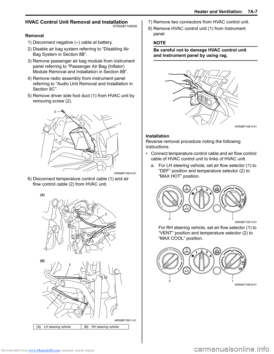
5) Remove driver side foot duct (1) from HVAC unit by removing screw (2).
6) Disconnect temperature control cable (1) and air flow control cable (2) from HVAC unit. 7) Remove two connectors from HVAC control unit.
8) Remove HVAC control unit (1) from instrument
panel.
NOTE
Be careful not to damage HVAC control unit
and instrument panel by using rag.
Installation
Reverse removal procedure noting the following
instructions.
• Connect temperature control cable and air flow control
cable of HVAC control unit to links of HVAC unit.
a. For LH steering vehicle, set air flow selector (1) to “DEF” position and temperature selector (2) to
“MAX HOT” position.
For RH steering vehicle, set air flow selector (1) to
“VENT” position and temperature selector (2) to
“MAX COOL” position.
[A]: LH steering vehicle [B]: RH steering vehicle
2
1
I4RS0B710010-01
2
1
1
2
[B] [A]
I4RS0B710011-01
1
I4RS0B710012-01
12I4RS0B710013-01
12I4RS0A710016-01
Page 945 of 1496
Downloaded from www.Manualslib.com manuals search engine Heater and Ventilation: 7A-9
Blower Speed Selector InspectionS7RS0B7106010
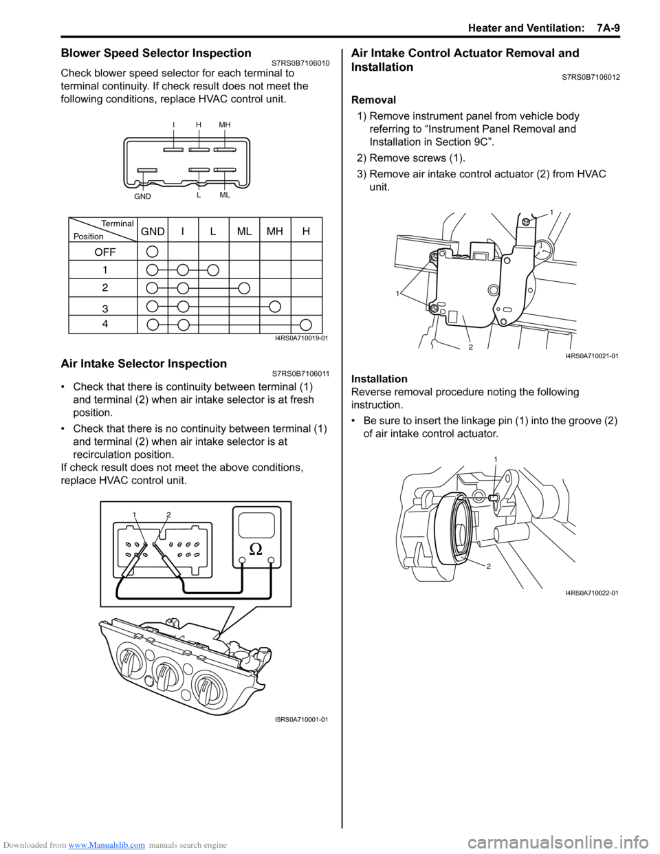
Check blower speed selector for each terminal to
terminal continuity. If check result does not meet the
following conditions, replace HVAC control unit.
Air Intake Selector InspectionS7RS0B7106011
• Check that there is continuity between terminal (1) and terminal (2) when air intake selector is at fresh
position.
• Check that there is no continuity between terminal (1) and terminal (2) when air intake selector is at
recirculation position.
If check result does not meet the above conditions,
replace HVAC control unit.
Air Intake Control Actuator Removal and
Installation
S7RS0B7106012
Removal
1) Remove instrument panel from vehicle body referring to “Instrum ent Panel Removal and
Installation in Section 9C”.
2) Remove screws (1).
3) Remove air intake control actuator (2) from HVAC unit.
Installation
Reverse removal procedure noting the following
instruction.
• Be sure to insert the linkage pin (1) into the groove (2) of air intake control actuator.
IHMH
GND LML
PositionTerminalI
OFF 1
2
3
4 LMLMHHGND
I4RS0A710019-01
1
2
I5RS0A710001-01
1 1
2
I4RS0A710021-01
1
2
I4RS0A710022-01