2005 SUZUKI JIMNY manifold
[x] Cancel search: manifoldPage 12 of 687

Downloaded from www.Manualslib.com manuals search engine GENERAL INFORMATION 0A-7
General Precautions
The WARNING and CAUTION below describe some general precautions that you should observe when servic-
ing a vehicle. These general precautions apply to many of the service procedures described in this manual, and
they will not necessarily be repeated with each procedure to which they apply.
Before starting any service work, cover fenders, seats
and any other parts that are likely to get scratched or
stained during servicing. Also, be aware that what you
wear (e.g, buttons) may cause damage to the vehicle’s
finish.
When performing service to electrical parts that does
not require use of battery power, disconnect the nega-
tive cable of the battery. WARNING:
Whenever raising a vehicle for service, be sure to follow the instructions under “Vehicle Lifting
Points” in this section.
When it is necessary to do service work with the engine running, make sure that the parking brake
is set fully and the transmission is in Neutral (for manual transmission vehicles) or Park (for auto-
matic transmission vehicles), Keep hands, hair, clothing, tools, etc. away from the fan and belts
when the engine is running.
When it is necessary to run the engine indoors, make sure that the exhaust gas is forced outdoors.
Do not perform service work in areas where combustible materials can come in contact with a hot
exhaust system. When working with toxic or flammable materials (such as gasoline and refriger-
ant), make sure that the area you work in is well-ventilated.
To avoid getting burned, keep away from hot metal parts such as the radiator, exhaust manifold,
tailpipe, muffler, etc.
New and used engine oil can be hazardous. Children and pets may be harmed by swallowing new or
used oil. Keep new and used oil and used engine oil filters away from children and pets.
Continuous contact with used engine oil has been found to cause [skin] cancer in laboratory ani-
mals. Brief contact with used oil may irritate skin. To minimize your exposure to used engine oil,
wear a long-sleeve shirt and moisture-proof gloves (such as dish washing gloves) when changing
engine oil. If engine oil contacts your skin, wash thoroughly with soap and water. Launder any
clothing or rags if wet with oil, recycle or properly dispose of used oil and filters.
Make sure the bonnet is fully closed and latched before driving. If it is not, it can fly up unexpectedly
during driving, obstructing your view and resulting in an accident.
Page 27 of 687

Downloaded from www.Manualslib.com manuals search engine 0A-22 GENERAL INFORMATION
LLH
LSPVLeft Hand
Load Sensing Proportioning Valve
TTBI
TCC
TCM
TP Sensor
TVV
TWC
2WDThrottle Body Fuel Injection
(Single-Point Fuel Injection, SPI)
Torque Converter Clutch
Transmission Control Module
(A/T Controller, A/T Control Mod-
ule)
Throttle Position Sensor
Thermal Vacuum Valve
(Thermal Vacuum Switching Valve,
TVSV, Bimetal Vacuum Switching
Valve, BVSV)
Three Way Catalytic Converter
(Three Way Catalyst)
2 Wheel Drive MMAF Sensor
MAP Sensor
Max
MFI
Min
MIL
M/TMass Air Flow Sensor
(Air Flow Sensor, AFS, Air Flow
Meter, AFM)
Manifold Absolute Pressure
Sensor (Pressure Sensor, PS)
Maximum
Multiport Fuel Injection
(Multipoint Fuel Injection)
Minimum
Malfunction Indicator Lamp
(“CHECK ENGINE” Light)
Manual Transmission
N NOx Nitrogen Oxides VVIN
VSSVehicle Identification Number
Vehicle Speed Sensor
OOBD
O/D
OHCOn-Board Diagnostic System
(Self-Diagnosis Function)
Overdrive
Over Head CamshaftWWU-OC
WU-TWCWarm Up Oxidation Catalytic
Converter
Warm Up Three Way Catalytic
Converter
PPNP
P/S
PSP Switch
PCM
PCVPark/Neutral Position
Power Steering
Power Steering Pressure Switch
(P/S Pressure Switch)
Powertrain Control Module
Positive Crankcase Ventilation
R RH Right Hand
SSAE
SDM
SFI
SOHCSociety of Automotive Engineers
Sensing and Diagnostic Module
(Air bag controller, Air bag control
module)
Sequential Multiport Fuel Injection
Single Over Head Camshaft
Page 63 of 687

Downloaded from www.Manualslib.com manuals search engine 1B-2 AIR CONDITIONING (OPTIONAL)
Evacuating ................................................. 1B-23
Evacuating procedure ............................ 1B-23
Charging .................................................... 1B-25
Charging procedure ............................... 1B-25
Removing Manifold Gauge Set .................. 1B-28
Leak Test ................................................... 1B-28
On-Vehicle Service ...................................... 1B-29
Service Precaution ..................................... 1B-29
Refrigerant line ....................................... 1B-29
Handling refrigerant HFC-134a
(R-134a) ................................................. 1B-30
Condenser Assembly ................................. 1B-31
Receiver / Dryer ......................................... 1B-32
Condenser Cooling Fan Assembly ............ 1B-33Cooling Unit (Evaporator) .......................... 1B-34
A/C Evaporator Thermistor (A/C Evaporator
Temperature Sensor)................................. 1B-37
Expansion Valve ........................................ 1B-37
Dual Pressure Switch ................................ 1B-38
A/C Switch ................................................. 1B-39
Condenser Cooling Fan Motor Relay ........ 1B-39
Compressor ............................................... 1B-39
Magnet Clutch............................................ 1B-41
Lip Type Seal ............................................. 1B-45
Tightening Torque Specification................ 1B-46
Required Service Materials ......................... 1B-47
Special Tools ............................................... 1B-47
Page 71 of 687
Downloaded from www.Manualslib.com manuals search engine 1B-10 AIR CONDITIONING (OPTIONAL)
Performance Diagnosis
1) Confirm that vehicle and environmental conditions are as fol-
lows.
Vehicle is not exposed to direct sun.
Ambient temperature is within 15 – 35 °C (59 – 95 °F).
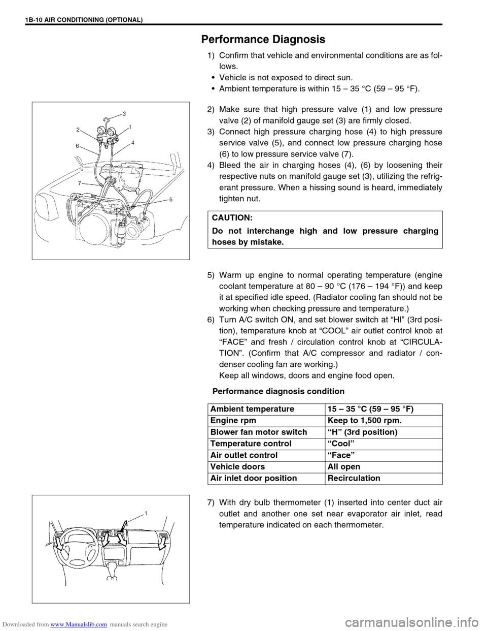
2) Make sure that high pressure valve (1) and low pressure
valve (2) of manifold gauge set (3) are firmly closed.
3) Connect high pressure charging hose (4) to high pressure
service valve (5), and connect low pressure charging hose
(6) to low pressure service valve (7).
4) Bleed the air in charging hoses (4), (6) by loosening their
respective nuts on manifold gauge set (3), utilizing the refrig-
erant pressure. When a hissing sound is heard, immediately
tighten nut.
5) Warm up engine to normal operating temperature (engine
coolant temperature at 80 – 90 °C (176 – 194 °F)) and keep
it at specified idle speed. (Radiator cooling fan should not be
working when checking pressure and temperature.)
6) Turn A/C switch ON, and set blower switch at “HI” (3rd posi-
tion), temperature knob at “COOL” air outlet control knob at
“FACE” and fresh / circulation control knob at “CIRCULA-
TION”. (Confirm that A/C compressor and radiator / con-
denser cooling fan are working.)
Keep all windows, doors and engine food open.
Performance diagnosis condition
7) With dry bulb thermometer (1) inserted into center duct air
outlet and another one set near evaporator air inlet, read
temperature indicated on each thermometer. CAUTION:
Do not interchange high and low pressure charging
hoses by mistake.
Ambient temperature 15 – 35 °C (59 – 95 °F)
Engine rpm Keep to 1,500 rpm.
Blower fan motor switch “H” (3rd position)
Temperature control “Cool”
Air outlet control “Face”
Vehicle doors All open
Air inlet door position Recirculation
Page 74 of 687

Downloaded from www.Manualslib.com manuals search engine AIR CONDITIONING (OPTIONAL) 1B-13
CROSSING POINT OF CENTER VENTILATION LOUVER TEMPERATURE AND RECIRCULATION AIR
INLET TEMPERATURE
Detail diagnosis table (Ambient temperature at 30°C (86°F))
Condition Possible Cause Correction
Crossing point is
higher than accept-
able range
(“E” area)Insufficient or excessive charge of refrigerant Check refrigerant pressure
Dirty or bent A/C evaporator fins Clean or repair
Air leakage from cooling (heater) unit or air duct Repair or replace
Malfunctioning, switch over function of door in
cooling (heater) unitRepair or replace
Compressor malfunction Check compressor
Crossing point is
lower than acceptable
range
(“F” area)Insufficient air volume from center duct (Heater
blower malfunction)Check blower motor and fan
Compressor malfunction Check compressor
Condition
Possible Cause Correction MANIFOLD
GAUGEMPa
(kg/cm
2)
(psi)Detail
Lo Hi
0.23 – 0.35
(2.3 – 3.5)
(33 – 50)1.4 – 1.75
(14 – 17.5)
(200 – 249)Normal condition
––
Negative
pressure0.5 – 0.6
(5 – 6)
(71.2 – 85.3)The low pressure side
reads a negative pres-
sure, and the high pres-
sure side reads an
extremely low pressure.
Presence of frost
around tubing to and
from receiver / dryer
and expansion valve.Dust particles or water
droplets are either stuck
or frozen inside expan-
sion valve, preventing the
refrigerant from flowing.Clean expansion valve.
Replace it if it cannot be
cleaned.
Replace receiver / dryer.
Evacuate the A/C sys-
tem and recharge with
fresh refrigerant.
Normal :
0.23 – 0.35
(2.3 – 3.5)
(33 – 50)
↑
↑ ↑ ↑ ↓
↓↓ ↓
Abnormal :
Negative
pressureNormal :
1.4 – 1.75
(14 – 17.5)
(200 – 249)
↑
↑ ↑ ↑ ↓
↓↓ ↓
Abnormal :
0.69 – 0.98
(7 – 10)
(100 – 142)During A/C operation,
the low pressure side
sometimes indicates
negative pressure, and
sometimes normal
pressure. Also high
pressure side reading
fluctuates between the
abnormal and normal
pressure.Expansion valve is frozen
due to moisture in the
system, and temporarily
shuts off the refrigeration
cycle.Replace expansion valve.
Replace receiver / dryer.
Evacuate A/C system
and recharge with fresh
refrigerant.
Page 75 of 687

Downloaded from www.Manualslib.com manuals search engine 1B-14 AIR CONDITIONING (OPTIONAL)
0.05 – 0.15
(0.5 – 1.5)
(4.2 – 21.3)
0.69 – 0.98
(7 – 10)
(100 – 142)Both low and high pres-
sure sides indicate low
readings.
Continuous air bub-
bles are visible through
sight glass.
Output air is slightly
cold.Insufficient refrigerant in
system.
(Refrigerant leaking)Using leak detector,
check for leaks and repair
as necessary.
Recharge refrigerant to a
specified amount.
If the pressure reading is
almost 0 when the mani-
fold gauges are attached,
check for any leaks,
repair them, and evacu-
ate the system.
0.4 – 0.6
(4 – 6)
(56.9 – 85.3)Pressure on low pres-
sure side is high.
Pressure on high pres-
sure side is low.
Both pressure becom-
ing equal right after A/C
is turned OFF.Internal leak in compres-
sor.Inspect compressor and
repair or replace as nec-
essary.
0.35 – 0.45
(3.5 – 4.5)
(50 – 64)
1.96 – 2.45
(20 – 25)
(285 – 355)Pressure on both low
and high pressure
sides is high.
Air bubbles are not visi-
ble even when engine
rpm is lowered.Overcharged A/C sys-
tem.Adjust refrigerant to
specified amount.
Faulty condenser cooling
operation.Clean condenser.
Faulty condenser cooling
fan operation.Inspect and repair con-
denser cooling fan.
Pressure on both low
and high pressure
sides is high.
Low pressure side tub-
ing is not cold when
touched.
Air bubbles are visible
through sight glass.Presence of air in A/C
system.
(Improperly evacuated)Replace receiver / dryer.
Inspect quantity of com-
pressor oil and presence
of contaminants in oil.
Evacuate system and
recharge with fresh
refrigerant.
0.45 – 0.55
(4.5 – 5.5)
(64 – 78)Pressure on both low
and high pressure
sides is high.
Large amount of frost
or dew on the low pres-
sure side tubing.Faulty expansion valve.
Refrigerant flow is not
regulated properly.Replace expansion valve. Condition
Possible Cause Correction MANIFOLD
GAUGEMPa
(kg/cm
2)
(psi)Detail
Lo Hi
Page 85 of 687

Downloaded from www.Manualslib.com manuals search engine 1B-24 AIR CONDITIONING (OPTIONAL)
1) Connect high charging hose (1) and low charging hose (2) of
manifold gauge set (3) respectively as follows:
High charging hose (1) → High pressure charging valve (4)
on discharge hose
Low charging hose (2) → Low pressure charging valve (5) on
suction hose
2) Attach center charging hose (6) of manifold gauge set (3) to
vacuum pump (7).
3) Operate vacuum pump (7), and then open discharge side
valve (Hi) (8) of manifold gauge set (3).
If there is no blockage in the system, there will be an indica-
tion on high pressure gauge (9).
In this case, open the other side valve (Lo) (10) of the set
and repair the system.
4) Approximately 10 minutes later, low pressure gauge (11)
should show a vacuum lower than –760 mmHg providing no
leakage exists.
5) Evacuation should be carried out for a total of at least 15
minutes.
6) Continue evacuation until low pressure gauge (9) indicates a
vacuum less than –760 mmHg, and then close both valves
(8), (10).
7) Stop vacuum pump (7). Disconnect center charging hose (6)
from pump inlet. Now, the system is ready for charging refrig-
erant. NOTE:
If the system does not show a vacuum below –760
mmHg, close both valves, stop vacuum pump and
watch movement of low pressure gauge.
Increase in the gauge reading suggests existence of
leakage. In this case, repair the system before continu-
ing its evacuation.
If the gauge shows a stable reading (suggesting no
leakage), continue evacuation.
Page 87 of 687

Downloaded from www.Manualslib.com manuals search engine 1B-26 AIR CONDITIONING (OPTIONAL)
2) Connect Low charging hose (1) and High charging hose (2)
of the manifold gauge set (3) in position. Thus open refriger-
ant container valve (4) to purge the charging line.
3) Open the high pressure side valve (5) and charge refrigerant
to system.
4) After a while, open the low pressure side valve (6) and close
the high pressure side valve (5).
5) Start engine and keep engine speed at 1500 r/min. Then,
operate air conditioning.
6) Charge A/C system with refrigerant in vapor state. At this
time, refrigerant container should be held upright.
7) When refrigerant container (3) is emptied, use the following
procedure to replace refrigerant container with a new refrig-
erant container (3).
a) Close low pressure valve.
b) Replace empty container (3) with a refrigerant container
which has been charged with refrigerant. When using
refrigerant container tap valve (4), use the following proce-
dure for replacement.
i) Retract needle (1) and remove refrigerant container tap
valve (4) by loosening its plate nut (2).
ii) Install previously-removed refrigerant container tap valve
(4) to a new refrigerant container (3).
c) Purge any air existing in center charging hose
When using refrigerant container tap valve, use the follow-
ing procedure to purge air.
i) Once fully tighten refrigerant container tap valve (1), and
then loosen (open) plate nut (2) slightly.
ii) Open low pressure side valve (3) of manifold gauge set
(4) a little.
iii) As soon as refrigerant comes out with a “hiss” through a
clearance between refrigerant container and tap valve,
tighten plate nut (2) as well as low pressure side valve (3).
iv) Turn handle of tap valve (1) clockwise so that its needle is
screwed into the new container to make a hole for refriger-
ant flow. WARNING:
Make sure that high pressure side valve is closed
securely.