2005 SUZUKI JIMNY exhaust
[x] Cancel search: exhaustPage 600 of 687

Downloaded from www.Manualslib.com manuals search engine ENGINE FUEL 6C-5
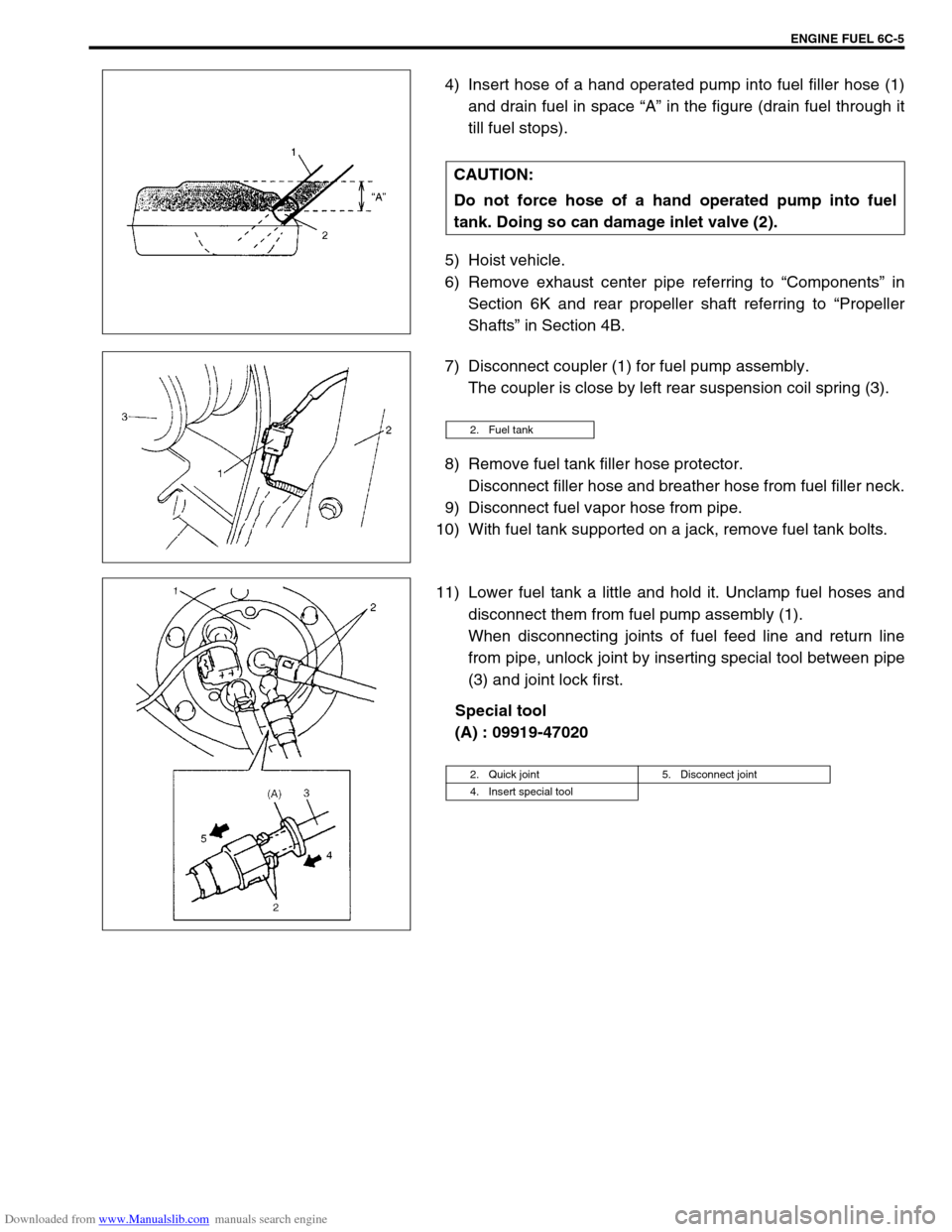
4) Insert hose of a hand operated pump into fuel filler hose (1)
and drain fuel in space “A” in the figure (drain fuel through it
till fuel stops).
5) Hoist vehicle.
6) Remove exhaust center pipe referring to “Components” in
Section 6K and rear propeller shaft referring to “Propeller
Shafts” in Section 4B.
7) Disconnect coupler (1) for fuel pump assembly.
The coupler is close by left rear suspension coil spring (3).
8) Remove fuel tank filler hose protector.
Disconnect filler hose and breather hose from fuel filler neck.
9) Disconnect fuel vapor hose from pipe.
10) With fuel tank supported on a jack, remove fuel tank bolts.
11) Lower fuel tank a little and hold it. Unclamp fuel hoses and
disconnect them from fuel pump assembly (1).
When disconnecting joints of fuel feed line and return line
from pipe, unlock joint by inserting special tool between pipe
(3) and joint lock first.
Special tool
(A) : 09919-47020 CAUTION:
Do not force hose of a hand operated pump into fuel
tank. Doing so can damage inlet valve (2).
2. Fuel tank
2. Quick joint 5. Disconnect joint
4. Insert special tool
Page 622 of 687

Downloaded from www.Manualslib.com manuals search engine ENGINE AND EMISSION CONTROL SYSTEM 6E-17
Idle mixture inspection / adjustment (vehicle without
heated oxygen sensor)
All vehicles not equipped with heated oxygen sensor are shipped
with their CO % factory adjusted as follows.
Engine idle mixture (CO %)
0.5 – 1.5 % at specified idle speed
Idle mixture adjustment should never be changed from the origi-
nal factory setting. However, if during diagnosis, the check indi-
cates idle mixture to be the cause of a driver performance
complaint or emission failure, the idle mixture can be adjusted
using the following procedures.
1) Check idle speed according to “Idle Speed / Idle Air Control
(IAC) Duty Inspection” in this section.
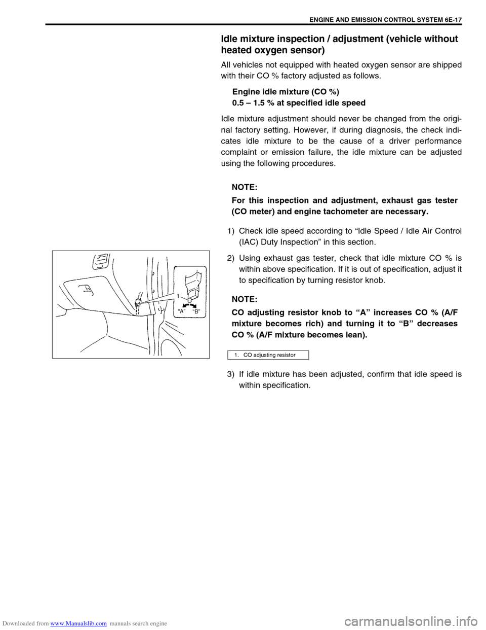
2) Using exhaust gas tester, check that idle mixture CO % is
within above specification. If it is out of specification, adjust it
to specification by turning resistor knob.
3) If idle mixture has been adjusted, confirm that idle speed is
within specification. NOTE:
For this inspection and adjustment, exhaust gas tester
(CO meter) and engine tachometer are necessary.
NOTE:
CO adjusting resistor knob to “A” increases CO % (A/F
mixture becomes rich) and turning it to “B” decreases
CO % (A/F mixture becomes lean).
1. CO adjusting resistor
Page 638 of 687

Downloaded from www.Manualslib.com manuals search engine ENGINE AND EMISSION CONTROL SYSTEM 6E-33
Tighten ECT sensor (1) to specified torque.
Tightening torque
ECT sensor (a) : 15 N·m (1.5 kg-m, 11.5 lb-ft)
Connect connector to ECT sensor (1) securely.
Refill coolant referring to “Cooling System Flush and Refill”
in Section 6B.
Heated oxygen sensor (Sensor-1 and sensor-2)
OXYGEN SENSOR HEATER INSPECTION
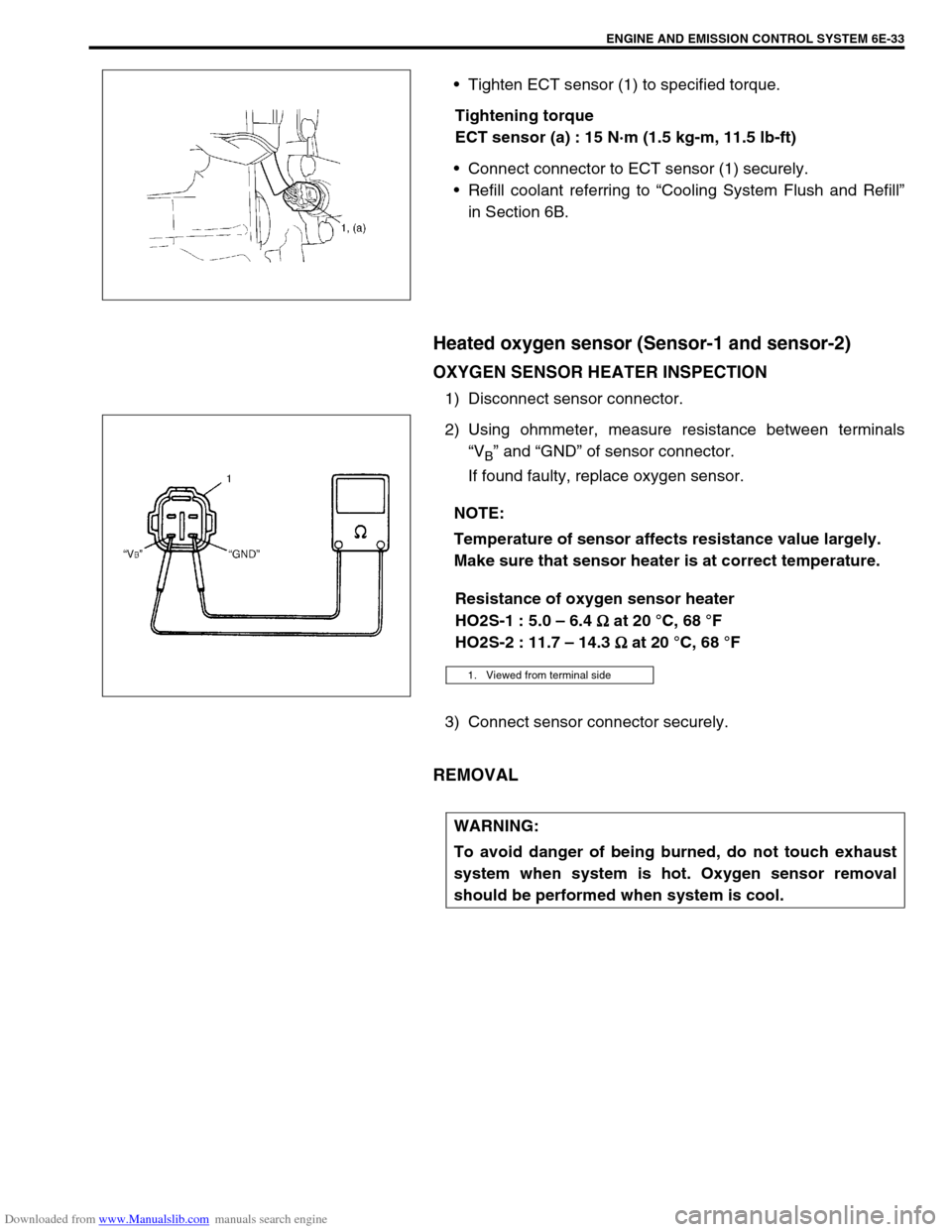
1) Disconnect sensor connector.
2) Using ohmmeter, measure resistance between terminals
“V
B” and “GND” of sensor connector.
If found faulty, replace oxygen sensor.
Resistance of oxygen sensor heater
HO2S-1 : 5.0 – 6.4
Ω
ΩΩ Ω at 20 °C, 68 °F
HO2S-2 : 11.7 – 14.3
Ω
ΩΩ Ω at 20 °C, 68 °F
3) Connect sensor connector securely.
REMOVAL
NOTE:
Temperature of sensor affects resistance value largely.
Make sure that sensor heater is at correct temperature.
1. Viewed from terminal side
WARNING:
To avoid danger of being burned, do not touch exhaust
system when system is hot. Oxygen sensor removal
should be performed when system is cool.
Page 639 of 687

Downloaded from www.Manualslib.com manuals search engine 6E-34 ENGINE AND EMISSION CONTROL SYSTEM
1) Disconnect negative cable at battery.
2) For sensor-1, remove exhaust manifold cover (1) and dis-
connect connector of heated oxygen sensor and release its
wire harness from clamps.
3) For sensor-2, disconnect connector of heated oxygen sensor
and release its wire harness from clamp. Hoist vehicle and
then remove exhaust No.1 pipe covers (3).
4) Remove heated oxygen sensor (2) from exhaust manifold or
exhaust No.1 pipe.
INSTALLATION
Reverse removal procedure noting the following.
Tighten heated oxygen sensor (2) to specified torque.
Tightening torque
Heated oxygen sensor (a) : 45 N·m (4.5 kg-m, 32.5 lb-ft)
Connect connector of heated oxygen sensor (2) and clamp
wire harness securely.
After installing heated oxygen sensor (2), start engine and
check that no exhaust gas leakage exists.
Camshaft position sensor
INSPECTION
Check camshaft position sensor referring to “DTC P0340 (No. 15)
Diag. Flow Table” in Section 6. If malfunction is found, replace.
REMOVAL
1) Disconnect negative cable at battery.
2) Disconnect connector from camshaft position sensor.
3) Remove camshaft position sensor from cylinder head.
INSTALLATION
1) Check that O-ring is free from damage.
2) Check that camshaft position sensor and signal rotor tooth
are free from any metal particles and damage.
3) Install camshaft position sensor to sensor case.
Tightening torque
Camshaft position sensor bolt
(a) : 10 N·m (1.0 kg-m, 7.5 lb-ft)
4) Connect connector to it securely.
5) Connect negative cable to battery.
[A] : HO2S-1
[B] : HO2S-2
Page 677 of 687

Downloaded from www.Manualslib.com manuals search engine 6H-10 CHARGING SYSTEM
1) Set parking brake and place automatic transmission in
PARK (NEUTRAL on manual transmission). Turn off ignition,
turn off lights and all other electrical loads.
2) Check electrolyte level. If it is below low level line, add dis-
tilled water.
3) Attach end of one jumper cable to positive terminal of
booster battery and the other end of the same cable to posi-
tive terminal of discharged battery. (Use 12-volt battery only
to jump start engine).
4) Attach one end of the remaining negative cable to negative
terminal of booster battery, and the other end to a solid
engine ground (such as exhaust manifold) at least 45 cm (18
in.) away from battery of vehicle being started.
5) Start engine of vehicle with booster battery and turn off elec-
trical accessories. Then start engine of the vehicle with dis-
charged battery.
6) Disconnect jumper cables in the exact reverse order.
WITH CHARGING EQUIPMENT
WARNING:
Departure from these conditions or procedure
described below could result in:
–Serious personal injury (particularly to eyes) or
property damage from such causes as battery explo-
sion, battery acid, or electrical burns.
–Damage to electronic components of either vehicle.
Remove rings, watches, and other jewelry. Wear
approved eye protection.
Be careful so that metal tools or jumper cables do not
contact positive battery terminal (or metal in contact
with it) and any other metal on vehicle, because a short
circuit could occur.
WARNING:
Do not connect negative cable directly to negative termi-
nal of dead battery.
CAUTION:
When jump starting engine with charging equipment, be
sure equipment used is 12-volt and negative ground. Do
not use 24-volt charging equipment. Using such equip-
ment can cause serious damage to electrical system or
electronic parts.
Page 686 of 687

Downloaded from www.Manualslib.com manuals search engine EXHAUST SYSTEM 6K-1
6F1
6F2
6G
6H
7D
7E
7F
7D
7E
7F
8A
8B
8C
8D
8E
9
7A1
6K
7C1
SECTION 6K
EXHAUST SYSTEM
CONTENTS
General Description ........................................6K-1
Maintenance ....................................................6K-1On-Vehicle Service ......................................... 6K-2
Exhaust Manifold .......................................... 6K-2
Exhaust Pipe ................................................. 6K-2
General Description
The exhaust system of this vehicle consists of the exhaust manifold, exhaust center pipe, muffler, seals, etc.
The catalytic converter is an emission control device added to the exhaust system to lower the level of Hydro-
carbon (HC), Carbon Monoxide (CO) and Oxides of Nitrogen (NOx) pollutants in the exhaust gas. The catalyst
in the catalytic converter is of “Three way” type.
Maintenance
At every interval of periodic maintenance service, and when vehicle is raised for other service, check exhaust
system as follows:
Check rubber mountings for damage, deterioration and out of position.
Check exhaust system for leakage, loose connection, dent and damage.
If bolts or nuts are loosened, tighten them to specified torque. Refer to “Components” in this section.
Check nearby body areas for damaged, missing, or mispositioned part, open seam, hole, loose connection
or any other defect which could permit exhaust fumes to seep into vehicle.
Make sure that exhaust system components have enough clearance from underbody to avoid overheating
and possible damage to passenger compartment carpet.
Any defect should be fixed at once. NOTE:
Whether following parts are used in the particular vehicle or not depends on specification. Be sure to
bear this in mind when performing service work.
Three-Way Catalytic Converter (TWC)
CAUTION:
Be sure to use UNLEADED FUEL for the catalytic converter equipped vehicle. Use of LEADED FUEL
will affect performance of the catalytic converter adversely to a great extent.
WARNING:
To avoid danger of being burned, do not touch exhaust system when system is hot.
Any service on exhaust system should be performed when system is cool.
Page 687 of 687

Downloaded from www.Manualslib.com manuals search engine 6K-2 EXHAUST SYSTEM
On-Vehicle Service
COMPONENTS
Exhaust Manifold
REMOVAL AND INSTALLATION
Refer to “Exhaust Manifold” in Section 6A1 for removal and installation procedures of exhaust manifold.
INSPECTION
Check seals for deterioration or damage.
Exhaust Pipe
REMOVAL AND INSTALLATION
For replacement of exhaust pipe, exhaust center pipe, muffler or any parts used to mount or connect them, be
sure to hoist vehicle and observe WARNING under “Maintenance” and the following.
1. Exhaust pipe (Vehicle without TWC) 6. Gasket 11. Mounting nuts
2. Exhaust pipe (Vehicle with TWC) 7. Spring Tightening torque
3. Exhaust center pipe 8. Mounting Do not reuse.
4. Muffler 9. Oxygen sensor
5. Seal ring 10. Mounting bolts
CAUTION:
Exhaust pipe with three way catalytic converter should not be exposed to any impulse. Do not drop it
or hit it against something.