Page 268 of 687
Downloaded from www.Manualslib.com manuals search engine BRAKES 5-7
Brake warning light
turns on when brake
is appliedBrake fluid leaking from brake line Investigate leaky point, correct it
and add brake fluid.
Insufficient amount of brake fluid Add brake fluid.
Faulty P & Differential valve (Differential switch) Replace.
Brake warning light
fails to turn on even
when parking brake is
appliedBulb burnt out Replace bulb.
Brake warning light circuit open Repair circuit.
ABS warning light
does not turn on for 2
sec. after ignition
switch has turned ON.Bulb burnt out Replace bulb.
ABS warning light circuit open, if equipped with
ABS (including check relay)Check system referring to “TABLE-
A” in Section 5E.
ABS warning light
remains on after igni-
tion switch has turned
on for 2 sec.Malfunctioning ABS, if equipped with ABS Check system referring to “TABLE-
B” in Section 5E. Condition Possible Cause Correction
Page 278 of 687

Downloaded from www.Manualslib.com manuals search engine BRAKES 5-17
On-Vehicle Service
Air Bleeding of Brake System
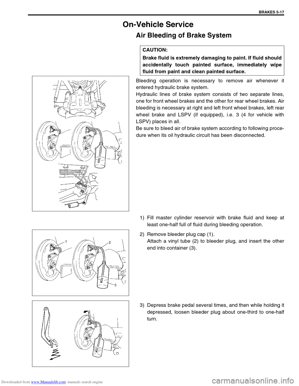
Bleeding operation is necessary to remove air whenever it
entered hydraulic brake system.
Hydraulic lines of brake system consists of two separate lines,
one for front wheel brakes and the other for rear wheel brakes. Air
bleeding is necessary at right and left front wheel brakes, left rear
wheel brake and LSPV (if equipped), i.e. 3 (4 for vehicle with
LSPV) places in all.
Be sure to bleed air of brake system according to following proce-
dure when its oil hydraulic circuit has been disconnected.
1) Fill master cylinder reservoir with brake fluid and keep at
least one-half full of fluid during bleeding operation.
2) Remove bleeder plug cap (1).
Attach a vinyl tube (2) to bleeder plug, and insert the other
end into container (3).
3) Depress brake pedal several times, and then while holding it
depressed, loosen bleeder plug about one-third to one-half
turn. CAUTION:
Brake fluid is extremely damaging to paint. If fluid should
accidentally touch painted surface, immediately wipe
fluid from paint and clean painted surface.
Page 284 of 687
Downloaded from www.Manualslib.com manuals search engine BRAKES 5-23
INSPECTION
Cylinder Slide Bush
Check slide bush for smooth movement as shown.
If it is found faulty, correct or replace. Apply rubber grease to bush
outer surface. Rubber grease should be the one whose viscosity
is less affected by such low temperature as – 40 °C (– 40 °F).
Bush Dust Boot and Cylinder Boot
Check boots for breakage, crack and damage. If defective,
replace.
Piston Seal
Excessive or uneven wear of pad lining may indicate unsmooth
return of the piston. In such a case, replace rubber seal.
1. Apply rubber grease
Page 290 of 687
Downloaded from www.Manualslib.com manuals search engine BRAKES 5-29
Rear Brake
Brake drum
REMOVAL
1) Hoist vehicle and pull up parking brake lever.
2) Remove wheel.
3) Release parking brake lever.
4) Loosen parking brake cable adjusting nut (1).
1. Brake back plate 5. Shoe return spring lower 9. Shoe hold down pin
2. Brake shoe 6. Adjuster lever 10. Wheel cylinder
: Apply brake fluid to piston cap
3. Spring and rod assembly 7. Adjuster spring Tightening torque
4. Parking brake shoe lever 8. Shoe hold down spring
Page 291 of 687

Downloaded from www.Manualslib.com manuals search engine 5-30 BRAKES
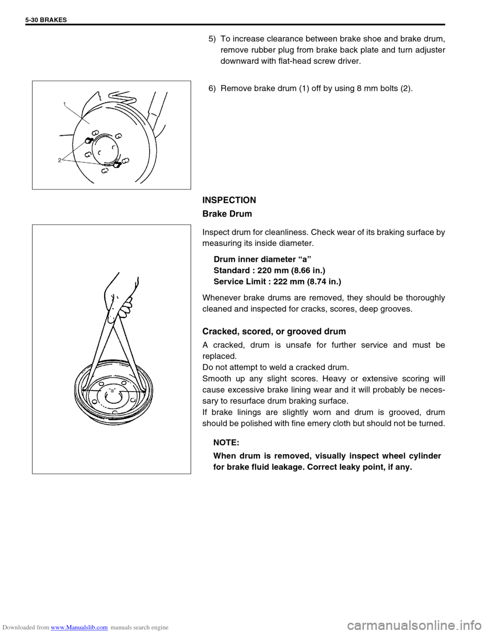
5) To increase clearance between brake shoe and brake drum,
remove rubber plug from brake back plate and turn adjuster
downward with flat-head screw driver.
6) Remove brake drum (1) off by using 8 mm bolts (2).
INSPECTION
Brake Drum
Inspect drum for cleanliness. Check wear of its braking surface by
measuring its inside diameter.
Drum inner diameter “a”
Standard : 220 mm (8.66 in.)
Service Limit : 222 mm (8.74 in.)
Whenever brake drums are removed, they should be thoroughly
cleaned and inspected for cracks, scores, deep grooves.
Cracked, scored, or grooved drum
A cracked, drum is unsafe for further service and must be
replaced.
Do not attempt to weld a cracked drum.
Smooth up any slight scores. Heavy or extensive scoring will
cause excessive brake lining wear and it will probably be neces-
sary to resurface drum braking surface.
If brake linings are slightly worn and drum is grooved, drum
should be polished with fine emery cloth but should not be turned.
NOTE:
When drum is removed, visually inspect wheel cylinder
for brake fluid leakage. Correct leaky point, if any.
Page 292 of 687

Downloaded from www.Manualslib.com manuals search engine BRAKES 5-31
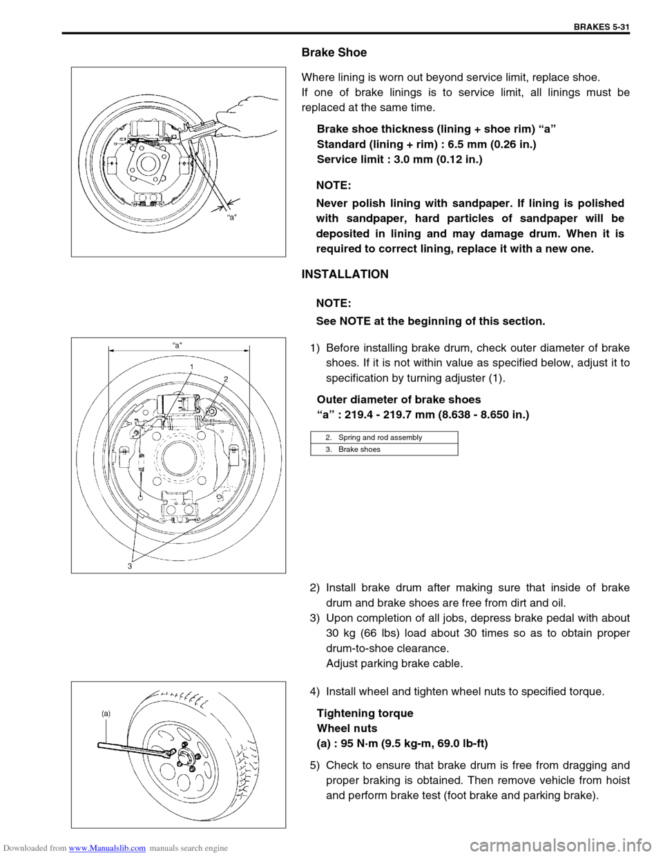
Brake Shoe
Where lining is worn out beyond service limit, replace shoe.
If one of brake linings is to service limit, all linings must be
replaced at the same time.
Brake shoe thickness (lining + shoe rim) “a”
Standard (lining + rim) : 6.5 mm (0.26 in.)
Service limit : 3.0 mm (0.12 in.)
INSTALLATION
1) Before installing brake drum, check outer diameter of brake
shoes. If it is not within value as specified below, adjust it to
specification by turning adjuster (1).
Outer diameter of brake shoes
“a” : 219.4 - 219.7 mm (8.638 - 8.650 in.)
2) Install brake drum after making sure that inside of brake
drum and brake shoes are free from dirt and oil.
3) Upon completion of all jobs, depress brake pedal with about
30 kg (66 lbs) load about 30 times so as to obtain proper
drum-to-shoe clearance.
Adjust parking brake cable.
4) Install wheel and tighten wheel nuts to specified torque.
Tightening torque
Wheel nuts
(a) : 95 N·m (9.5 kg-m, 69.0 lb-ft)
5) Check to ensure that brake drum is free from dragging and
proper braking is obtained. Then remove vehicle from hoist
and perform brake test (foot brake and parking brake). NOTE:
Never polish lining with sandpaper. If lining is polished
with sandpaper, hard particles of sandpaper will be
deposited in lining and may damage drum. When it is
required to correct lining, replace it with a new one.
NOTE:
See NOTE at the beginning of this section.
2. Spring and rod assembly
3. Brake shoes
Page 293 of 687
Downloaded from www.Manualslib.com manuals search engine 5-32 BRAKES
Brake shoe
REMOVAL
1) Remove brake drum referring to “Brake Drum” in this sec-
tion.
2) Remove shoe return spring lower (3), spring and rod assem-
bly (4) and shoe hold down springs (2) by turning shoe hold
down pins (1).
3) Remove parking brake shoe lever (5) from brake back plate.
INSPECT
Inspect lever for free movement against brake shoe web. If
defective, correct or replace.
Inspect ratchet or thread rod part for wear, sticking and cor-
rosion.
Inspect for damage or weakening.
Inspect each part with arrow for rust. If found defective,
replace.
INSTALLATION
Assemble parts as shown in reverse order of removal.
1) Apply rubber grease to brake back plate and parking brake
shoe lever as shown in the figure. WARNING:
Use special care when installing brake shoe return
spring. Failure in its proper installation may allow it to
spring back and cause personal injury.
1. Apply rubber grease
Page 294 of 687
Downloaded from www.Manualslib.com manuals search engine BRAKES 5-33
2) Install shoe hold down springs (2) by pushing them down in
place and turning hold down pins (1).
3) Install shoe return spring and parking brake shoe lever
spring.
4) For procedure hereafter, refer to “Brake Drum” in this sec-
tion.
Wheel Cylinder
REMOVAL
1) Remove brake drum referring to “Brake Drum” in this sec-
tion.
2) Remove brake shoe referring to “Brake Shoe” in this section.
3) Loosen brake pipe flare nut (or nuts) but only within the
extent that fluid does not leak.
4) Remove wheel cylinder mounting bolts. Disconnect brake
pipe (or pipes) from wheel cylinder and put wheel cylinder
breather plug cap (1) onto pipe to prevent fluid from spilling.
INSPECTION
Inspect wheel cylinder disassembled parts for wear, cracks, cor-
rosion or damage.
3. Shoe return spring lower
4. Spring and rod assembly
5. Adjuster lever
6. Adjuster spring
NOTE:
Clean wheel cylinder components with brake fluid.