Page 140 of 687

Downloaded from www.Manualslib.com manuals search engine POWER STEERING (P/S) SYSTEM (If equipped) 3B1-9
3) After running engine at idling speed for 3 to 5 seconds, stop
it and add fluid up to specified level. Repeat this step a few
times.
4) Set steering gear box (1) to state [A] as shown.
5) With engine running at idling speed, turn input shaft by using
special tool in both directions as far as it locks till all foams
are gone.
Special tool
(B) : 09944-18211
6) Perform Step 5) but with steering gear box in state [B] this
time and then in state [C].
7) Set input shaft at neutral position (straight position).
8) Remove (special) tools and install steering gear box to vehi-
cle and P/S pipe / hose to steering gear box referring to
“Power Steering (P/S) Gear Box” in this section.
9) Bleed air in P/S system referring to “Air Bleeding Procedure”
in this section.
10) Install pitman arm and steering lower shaft to steering gear
box. NOTE:
Don’t operate steering system for this step.
NOTE:
Add fluid into P/S fluid reservoir whenever its level
lowers while servicing.
Turn input shaft till it locks, return it a little and turn it
again in the same direction till it locks. Repeat this
some times.
NOTE:
To change of state of gear box from [A] to [B] and from
[B] to [C], turn gear box in arrow direction in figures [A]
and [B].
NOTE:
As input shaft makes 4 full turns from lock to lock, neu-
tral position is obtained by turning it till it locks and turn-
ing it back by 2 full turns.
2. Vinyl tube (See-through tube)
NOTE:
Don’t install pitman arm and steering lower shaft to
steering gear box.
Installation of these parts will cause input shaft and/or
sector shaft to turn, allowing air to enter gear box.
Plug up opening after pipe or hose disconnection.
Page 141 of 687

Downloaded from www.Manualslib.com manuals search engine 3B1-10 POWER STEERING (P/S) SYSTEM (If equipped)
Hydraulic Pressure In P/S Circuit Check
1) Clean where pipe is connected thoroughly, then disconnect
high pressure hose from high pressure pipe connector and
connect oil pressure gauge (special tool) as shown.
Special tool
(A) : 09915-77410
(B) : 09915-77420
2) Bleed air.
3) With engine running at idling speed, keep turning steering
wheel to the right and left till fluid in P/S fluid reservoir is
warmed to 50 to 60 °C (122 – 140 °F)
4) Back pressure check
With engine running at idling speed and hands off from
steering wheel, check hydraulic pressure.
If back pressure exceeds 980 kPa (10 kg/cm
2, 142 psi),
check control valve and pipes for obstruction.
Back pressure : 980 kPa (10 kg/cm
2, 142 psi)
1. To gear box 4. Union bolt
2. Attachment 5. Pressure hose
3. Washer
1. P/S fluid reservoir 5. Low pressure side
2. P/S pump 6. High pressure side
3. Steering gear box 7. Valve (open)
4. Oil pump pressure gauge
Page 142 of 687

Downloaded from www.Manualslib.com manuals search engine POWER STEERING (P/S) SYSTEM (If equipped) 3B1-11
5) Relief pressure check
a) Increase engine speed to about 1,500 to 1,600 rpm.
Close valve (6) gradually while watching pressure increase
indicated on gauge (4) and take reading of relief pressure
(maximum hydraulic pressure).
If higher than 8,400 kPa (85 kg/cm
2, 1208 psi), malfunction
of relief valve.
If lower than 6,400 kPa (65 kg/cm
2, 925 psi), failure of P/S
pump or settling of relief valve spring.
Relief pressure
6,400 – 8,400 kPa (65 – 85 kg/cm
2, 925 – 1208 psi)
b) Next, open gauge valve (6) fully and increase engine speed
to about 1,500 to 1,600 r/min. Then turn steering wheel to
the left or right fully and take reading of relief pressure.
If lower than 6,400 kPa (65 kg/cm
2, 1280 psi), failure in
steering gear.
Relief pressure
6,400 – 8,400 kPa (65 – 85 kg/cm
2, 925 – 1208 psi) CAUTION:
Be sure not to keep gauge valve closed for longer than
10 seconds.
Never keep steering wheel turned fully for longer than
10 seconds.
1. P/S fluid reservoir 3. Steering gear box
2. P/S pump 5. High pressure side
1. P/S fluid reservoir 4. Oil pressure gauge
2. P/S pump 5. High pressure side
3. Steering gear box
Page 147 of 687
Downloaded from www.Manualslib.com manuals search engine 3B1-16 POWER STEERING (P/S) SYSTEM (If equipped)
7) Apply power steering fluid to sliding surface of cam ring (1).
8) Install cam ring (1) to pump body. The tapered end of cam
ring (1) should face the side plate (2).
9) Apply power steering fluid to each vane (2).
10) Install vanes (10 pipes) (2) to rotor (1).
11) Apply power steering fluid to O-ring (1) and fit it to pump
body.
12) Install O-ring (1) to pump body.
13) Apply power steering fluid to sliding surface of pump cover
(1) and rotor.
14) Match the dowel pins (2) to the holes of the cover plate as
shown and install pump cover to pump body.
15) Tighten pump cover bolts to specified torque.
Tightening torque
Oil pump cover bolts
(a) : 28 N·m (2.8 kg-m, 20.0 lb-ft)
NOTE:
After installing pump cover (1), check to make sure that
shaft can be turned by hand.
Page 149 of 687

Downloaded from www.Manualslib.com manuals search engine 3B1-18 POWER STEERING (P/S) SYSTEM (If equipped)
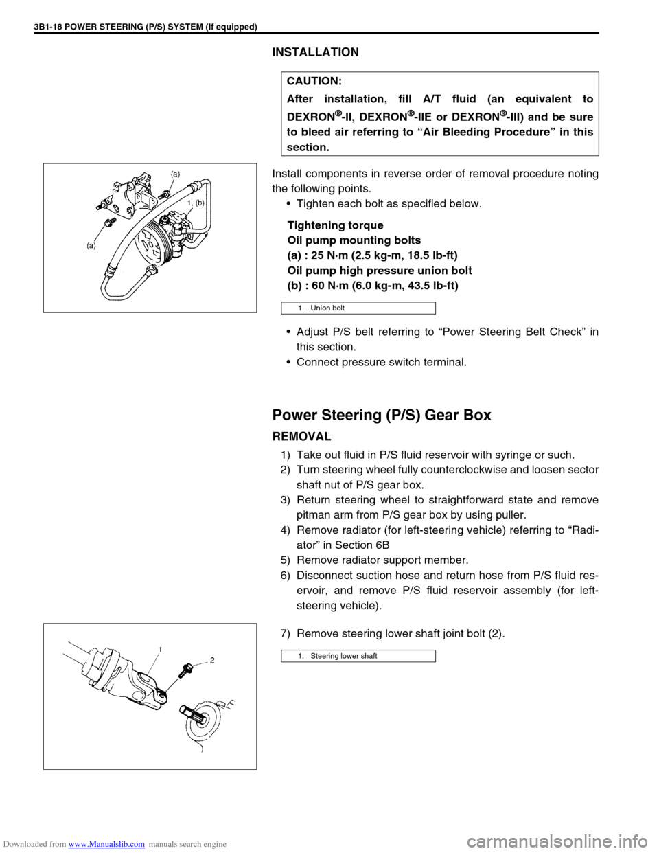
INSTALLATION
Install components in reverse order of removal procedure noting
the following points.
Tighten each bolt as specified below.
Tightening torque
Oil pump mounting bolts
(a) : 25 N·m (2.5 kg-m, 18.5 lb-ft)
Oil pump high pressure union bolt
(b) : 60 N·m (6.0 kg-m, 43.5 lb-ft)
Adjust P/S belt referring to “Power Steering Belt Check” in
this section.
Connect pressure switch terminal.
Power Steering (P/S) Gear Box
REMOVAL
1) Take out fluid in P/S fluid reservoir with syringe or such.
2) Turn steering wheel fully counterclockwise and loosen sector
shaft nut of P/S gear box.
3) Return steering wheel to straightforward state and remove
pitman arm from P/S gear box by using puller.
4) Remove radiator (for left-steering vehicle) referring to “Radi-
ator” in Section 6B
5) Remove radiator support member.
6) Disconnect suction hose and return hose from P/S fluid res-
ervoir, and remove P/S fluid reservoir assembly (for left-
steering vehicle).
7) Remove steering lower shaft joint bolt (2).CAUTION:
After installation, fill A/T fluid (an equivalent to
DEXRON
®-II, DEXRON®-IIE or DEXRON®-III) and be sure
to bleed air referring to “Air Bleeding Procedure” in this
section.
1. Union bolt
1. Steering lower shaft
Page 150 of 687

Downloaded from www.Manualslib.com manuals search engine POWER STEERING (P/S) SYSTEM (If equipped) 3B1-19
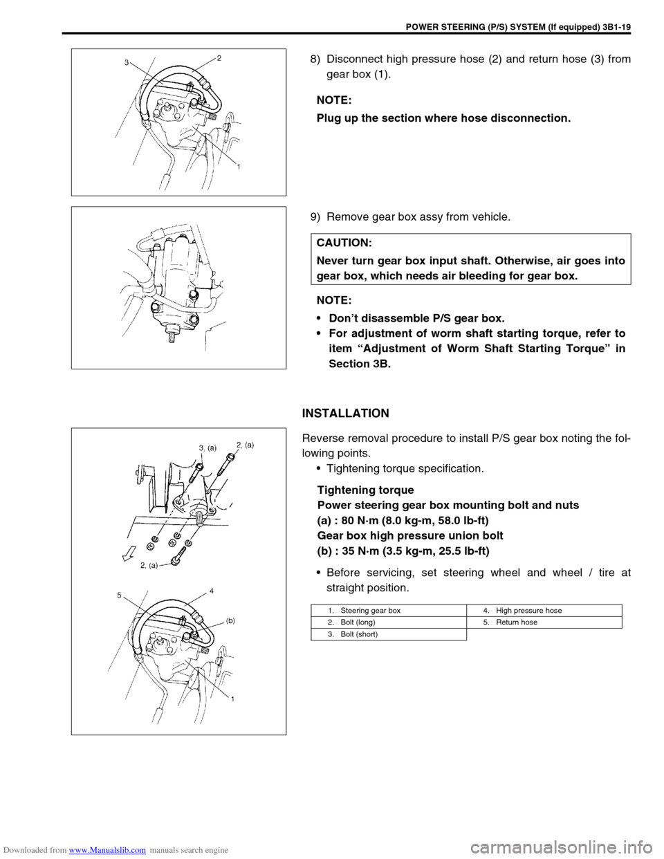
8) Disconnect high pressure hose (2) and return hose (3) from
gear box (1).
9) Remove gear box assy from vehicle.
INSTALLATION
Reverse removal procedure to install P/S gear box noting the fol-
lowing points.
Tightening torque specification.
Tightening torque
Power steering gear box mounting bolt and nuts
(a) : 80 N·m (8.0 kg-m, 58.0 lb-ft)
Gear box high pressure union bolt
(b) : 35 N·m (3.5 kg-m, 25.5 lb-ft)
Before servicing, set steering wheel and wheel / tire at
straight position. NOTE:
Plug up the section where hose disconnection.
CAUTION:
Never turn gear box input shaft. Otherwise, air goes into
gear box, which needs air bleeding for gear box.
NOTE:
Don’t disassemble P/S gear box.
For adjustment of worm shaft starting torque, refer to
item “Adjustment of Worm Shaft Starting Torque” in
Section 3B.
1. Steering gear box 4. High pressure hose
2. Bolt (long) 5. Return hose
3. Bolt (short)
Page 157 of 687

Downloaded from www.Manualslib.com manuals search engine 3C-4 STEERING WHEEL AND COLUMN
Drive Air Bag (Inflator) Module (For Vehicle
with Air Bag System)
REMOVAL
1) Disconnect negative battery cable at battery terminal.
2) Disable air bag system. Refer to “Disabling Air Bag System”
in Section 10B.
3) Remove steering wheel side cap (1) of left side.
4) Loosen 2 bolts (2) mounting driver air bag (inflator) module
till it turns freely, pull them out and fix them to bolt clamps (3).
5) Remove driver air bag (inflator) module (1) from steering
wheel.
6) Disconnect yellow connector (2) in order a) – b) as shown.
INSPECTION
WARNING:
When handling an air bag (inflator) module, be sure to
read “Service Precautions” given earlier in this section
and observe each instruction. Failure to follow them
could cause a damage to the air bag (inflator) module or
result in personal injury.
WARNING:
Never disassemble driver air bag (inflator) module or
measure its resistance. Otherwise, personal injury may
result.
CAUTION:
If air bag (inflator) module was dropped from a height of
90 cm (3 ft) or more, it should be replaced.
Page 158 of 687

Downloaded from www.Manualslib.com manuals search engine STEERING WHEEL AND COLUMN 3C-5
Check air bag (inflator) module visually and if any of the following
is found, replace it with a new one.
Air bag being deployed
Trim cover (1) (pad surface) being cracked
Wire harness (3) or connector being damaged
Air bag (inflator) module being damaged or having been
exposed to strong impact (dropped)
INSTALLATION
1) Check that horn wire is connected to horn terminal securely.
2) Connect yellow connector (1) of driver air bag (inflator) mod-
ule (3) pushing connector till it is locked.
3) Install driver air bag (inflator) module to steering wheel, tak-
ing care so that no part of wire harness is caught between
them.
4) Make sure that clearance between module and steering
wheel is uniform all the way.
5) Tighten driver air bag (inflator) module mounting bolts (1) to
specified torque.
Tightening torque
Driver air bag (inflator) module mounting bolts
(a) : 9 N·m (0.9 kg-m, 6.5 lb-ft)
6) Install steering wheel side cap (2).
7) Connect negative battery cable.
8) Enable air bag system. Refer to “Enabling Air Bag System”
under “Service Precautions” in Section 10B.
Steering Wheel
2. Inflator case
CAUTION:
For vehicle with air bag system
Removal of the steering wheel allows the contact coil to
turn freely but do not turn the contact coil (on the combi-
nation switch) more than allowable number of turns
(about two and a half turns from the center position
clockwise or counterclockwise respectively), or coil will
break.