2005 SUZUKI JIMNY egr
[x] Cancel search: egrPage 563 of 687

Downloaded from www.Manualslib.com manuals search engine 6A1-82 ENGINE MECHANICAL (M13 ENGINE)
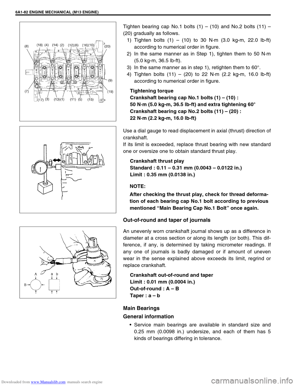
Tighten bearing cap No.1 bolts (1) – (10) and No.2 bolts (11) –
(20) gradually as follows.
1) Tighten bolts (1) – (10) to 30 N·m (3.0 kg-m, 22.0 lb-ft)
according to numerical order in figure.
2) In the same manner as in Step 1), tighten them to 50 N·m
(5.0 kg-m, 36.5 lb-ft).
3) In the same manner as in step 1), retighten them to 60°.
4) Tighten bolts (11) – (20) to 22 N·m (2.2 kg-m, 16.0 lb-ft)
according to numerical order in figure.
Tightening torque
Crankshaft bearing cap No.1 bolts (1) – (10) :
50 N·m (5.0 kg-m, 36.5 lb-ft) and extra tightening 60°
Crankshaft bearing cap No.2 bolts (11) – (20) :
22 N·m (2.2 kg-m, 16.0 lb-ft)
Use a dial gauge to read displacement in axial (thrust) direction of
crankshaft.
If its limit is exceeded, replace thrust bearing with new standard
one or oversize one to obtain standard thrust play.
Crankshaft thrust play
Standard : 0.11 – 0.31 mm (0.0043 – 0.0122 in.)
Limit : 0.35 mm (0.0138 in.)
Out-of-round and taper of journals
An unevenly worn crankshaft journal shows up as a difference in
diameter at a cross section or along its length (or both). This dif-
ference, if any, is determined by taking micrometer readings. If
any one of journals is badly damaged or if amount of uneven
wear in the sense explained above exceeds its limit, regrind or
replace crankshaft.
Crankshaft out-of-round and taper
Limit : 0.01 mm (0.0004 in.)
Out-of-round : A – B
Taper : a – b
Main Bearings
General information
Service main bearings are available in standard size and
0.25 mm (0.0098 in.) undersize, and each of them has 5
kinds of bearings differing in tolerance.
NOTE:
After checking the thrust play, check for thread deforma-
tion of each bearing cap No.1 bolt according to previous
mentioned “Main Bearing Cap No.1 Bolt” once again.
Page 565 of 687

Downloaded from www.Manualslib.com manuals search engine 6A1-84 ENGINE MECHANICAL (M13 ENGINE)
5) Remove bearing caps and using scale (1) on gauging plastic
(2) envelop, measure gauging plastic width at its widest
point. If clearance exceeds its limit, replace bearing. Always
replace both upper and lower inserts as a unit.
A new standard bearing may produce proper clearance. If
not, it will be necessary to regrind crankshaft journal for use
of 0.25 mm undersize bearing.
After selecting new bearing, recheck clearance.
Main bearing clearance
Standard : 0.025 – 0.045 mm (0.0010 – 0.0018 in.)
Limit : 0.065 mm (0.0026 in.)
Selection of main bearings
STANDARD BEARING:
If bearing is in malcondition, or bearing clearance is out of specifi-
cation, select a new standard bearing according to the following
procedure and install it.
1) First check journal diameter. As shown in figure, crank web
No.2 has stamped numbers.
Three kinds of numbers (“1”, “2” and “3”) represent the fol-
lowing journal diameters.
Stamped numbers on crank web No.2 represent journal
diameters marked with an arrow in figure respectively.
For example, stamped number “1” indicates that correspond-
ing journal diameter is 44.994 – 45.000 mm (1.7714 –
1.7717 in.).
Crankshaft journal diameter NOTE:
After checking the bearing clearance, check for thread
deformation of each bearing cap No.1 bolt according to
previous mentioned Step 4) once again.
Stamped numbers Journal diameter
144.994 – 45.000 mm
(1.7714 – 1.7717 in.)
244.988 – 44.994 mm
(1.7712 – 1.7714 in.)
344.982 – 44.988 mm
(1.7709 – 1.7712 in.)
Page 568 of 687

Downloaded from www.Manualslib.com manuals search engine ENGINE MECHANICAL (M13 ENGINE) 6A1-87
If necessary, regrind crankshaft journal and select undersize
bearing to use with it as follows.
a) Regrind journal to the following finished diameter.
Finished diameter
44.732 – 44.750 mm (1.7611 – 1.7618 in.)
1) Using micrometer, measure reground journal diameter.
Measurement should be taken in two directions perpendicu-
lar to each other in order to check for out-of-round.
2) Using journal diameter measured above and alphabets
stamped on cylinder block, select an undersize bearing by
referring to table given below.
Check bearing clearance with newly selected undersize
bearing.
Specification of undersize crankshaft main bearing
Rear Oil Seal
Carefully inspect oil seal (1) for wear or damage.
If its lip is worn or damaged, replace it.
For oil seal installation, press-fit rear oil seal (1) to oil seal hous-
ing (2) by using special tool as shown in the figure.
Special tool
(A) : 09911-97820
Crank rear oil seal installing position
“a” : 3 mm (0.12 in.)
Measured journal diameter
44.744 – 44.750 mm
(1.7616 – 1.7618 in.)44.738 – 44.744 mm
(1.7613 – 1.7616 in.)44.732 – 44.738 mm
(1.7611 – 1.7613 in.)
Alphabets stamped
on cylinder blockA Red and Pink Red and Purple Red and Brown
B Red and Purple Red and Brown Red and Green
C Red and Brown Red and Green Red and Black
Undersize bearing to be installed
Page 606 of 687

Downloaded from www.Manualslib.com manuals search engine ENGINE AND EMISSION CONTROL SYSTEM 6E-1
6F1
6F2
6G
7C1
7D
7E
7A
7A1
7B1
7C1
7D
7E
7F
8A
8B
8C
8D
6H
6E
10
10A
10B
SECTION 6E
ENGINE AND EMISSION CONTROL SYSTEM
CONTENTS
General Description ....................................... 6E-3
Air Intake System ......................................... 6E-5
Fuel Delivery System ................................... 6E-6
Fuel pump ................................................ 6E-6
Electronic Control System ............................ 6E-7
Engine & emission control input / output
table.......................................................... 6E-8
On-Vehicle Service....................................... 6E-15
Accelerator cable adjustment ................. 6E-15
Idle speed / idle air control (IAC) duty
inspection ............................................... 6E-15
Idle mixture inspection / adjustment
(vehicle without heated oxygen
sensor) ................................................... 6E-17
Air Intake System ....................................... 6E-18
Throttle body .......................................... 6E-18
Idle air control valve (IAC valve)............. 6E-21
Fuel Delivery System ................................. 6E-22
Fuel pressure inspection ........................ 6E-22
Fuel pump .............................................. 6E-23
Fuel pressure regulator .......................... 6E-24
Fuel injector ............................................ 6E-25
Electronic Control System .......................... 6E-29Engine control module (ECM) ................ 6E-29
Manifold absolute pressure sensor (MAP
sensor) ................................................... 6E-29
Throttle position sensor (TP sensor) ...... 6E-30
Intake air temperature sensor
(IAT sensor) ........................................... 6E-31
Engine coolant temperature sensor
(ECT sensor) .......................................... 6E-32
Heated oxygen sensor
(Sensor-1 and sensor-2) ........................ 6E-33
Camshaft position sensor....................... 6E-34
Crankshaft position sensor..................... 6E-35
Vehicle speed sensor (VSS) .................. 6E-36
Fuel level sensor (GAUGE).................... 6E-36
Knock sensor ......................................... 6E-36
Main relay, fuel pump relay and A/C
condenser fan control relay .................... 6E-36
Fuel cut operation .................................. 6E-37
A/C condenser fan control system ......... 6E-37
A/C condenser fan ................................. 6E-37
Output signals of throttle valve opening
and engine coolant temp.
(Vehicle with A/T only) ........................... 6E-38
Emission Control System ........................... 6E-38 WARNING:
For vehicles equipped with Supplemental Restraint (Air Bag) System:
Service on and around the air bag system components or wiring must be performed only by an
authorized SUZUKI dealer. Refer to “Air Bag System Components and Wiring Location View” under
“General Description” in air bag system section in order to confirm whether you are performing ser-
vice on or near the air bag system components or wiring. Please observe all WARNINGS and “Ser-
vice Precautions” under “On-Vehicle Service” in air bag system section before performing service
on or around the air bag system components or wiring. Failure to follow WARNINGS could result in
unintentional activation of the system or could render the system inoperative. Either of these two
conditions may result in severe injury.
Technical service work must be started at least 90 seconds after the ignition switch is turned to the
“LOCK” position and the negative cable is disconnected from the battery. Otherwise, the system
may be activated by reserve energy in the Sensing and Diagnostic Module (SDM).
NOTE:
Whether following systems (parts) are used in the particular vehicle or not depends on specifications.
Be sure to bear this in mind when performing service work.
EGR valve
Heated oxygen sensor (s) or CO adjusting resistor
Three way catalytic converter (TWC) and warm up three-way catalytic converter (WU-TWC)
Page 607 of 687

Downloaded from www.Manualslib.com manuals search engine 6E-2 ENGINE AND EMISSION CONTROL SYSTEM
EGR system (If equipped) ...................... 6E-38
Evaporative emission (EVAP) control
system .................................................... 6E-39
PCV system ........................................... 6E-41Special Tools ............................................... 6E-42
Tightening Torque Specifications .............. 6E-43
Page 608 of 687

Downloaded from www.Manualslib.com manuals search engine ENGINE AND EMISSION CONTROL SYSTEM 6E-3
General Description
The engine and emission control system is divided into 4 major sub-systems: air intake system, fuel delivery
system, electronic control system and emission control system.
Air intake system includes air cleaner, throttle body, IAC valve and intake manifold.
Fuel delivery system includes fuel pump, delivery pipe, fuel pressure regulator, etc. Electronic control system
includes ECM, various sensors and controlled devices.
Emission control system includes EGR, EVAP and PCV system.
Page 610 of 687

Downloaded from www.Manualslib.com manuals search engine ENGINE AND EMISSION CONTROL SYSTEM 6E-5
Air Intake System
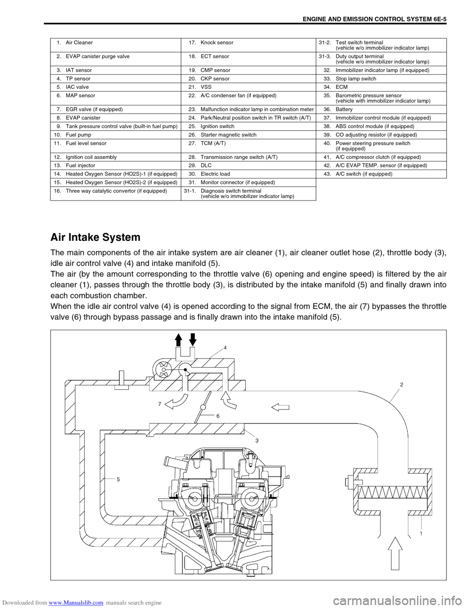
The main components of the air intake system are air cleaner (1), air cleaner outlet hose (2), throttle body (3),
idle air control valve (4) and intake manifold (5).
The air (by the amount corresponding to the throttle valve (6) opening and engine speed) is filtered by the air
cleaner (1), passes through the throttle body (3), is distributed by the intake manifold (5) and finally drawn into
each combustion chamber.
When the idle air control valve (4) is opened according to the signal from ECM, the air (7) bypasses the throttle
valve (6) through bypass passage and is finally drawn into the intake manifold (5).
1. Air Cleaner 17. Knock sensor 31-2. Test switch terminal
(vehicle w/o immobilizer indicator lamp)
2. EVAP canister purge valve 18. ECT sensor 31-3. Duty output terminal
(vehicle w/o immobilizer indicator lamp)
3. IAT sensor 19. CMP sensor 32. Immobilizer indicator lamp (if equipped)
4. TP sensor 20. CKP sensor 33. Stop lamp switch
5. IAC valve 21. VSS 34. ECM
6. MAP sensor 22. A/C condenser fan (if equipped) 35. Barometric pressure sensor
(vehicle with immobilizer indicator lamp)
7. EGR valve (if equipped) 23. Malfunction indicator lamp in combination meter 36. Battery
8. EVAP canister 24. Park/Neutral position switch in TR switch (A/T) 37. Immobilizer control module (if equipped)
9. Tank pressure control valve (built-in fuel pump) 25. Ignition switch 38. ABS control module (if equipped)
10. Fuel pump 26. Starter magnetic switch 39. CO adjusting resistor (if equipped)
11. Fuel level sensor 27. TCM (A/T) 40. Power steering pressure switch
(if equipped)
12. Ignition coil assembly 28. Transmission range switch (A/T) 41. A/C compressor clutch (if equipped)
13. Fuel injector 29. DLC 42. A/C EVAP TEMP. sensor (if equipped)
14. Heated Oxygen Sensor (HO2S)-1 (if equipped) 30. Electric load 43. A/C switch (if equipped)
15. Heated Oxygen Sensor (HO2S)-2 (if equipped) 31. Monitor connector (if equipped)
16. Three way catalytic convertor (if equipped) 31-1. Diagnosis switch terminal
(vehicle w/o immobilizer indicator lamp)
Page 612 of 687

Downloaded from www.Manualslib.com manuals search engine ENGINE AND EMISSION CONTROL SYSTEM 6E-7
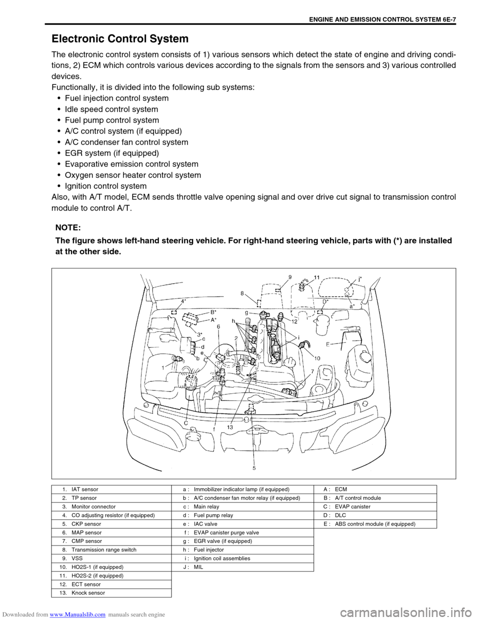
Electronic Control System
The electronic control system consists of 1) various sensors which detect the state of engine and driving condi-
tions, 2) ECM which controls various devices according to the signals from the sensors and 3) various controlled
devices.
Functionally, it is divided into the following sub systems:
Fuel injection control system
Idle speed control system
Fuel pump control system
A/C control system (if equipped)
A/C condenser fan control system
EGR system (if equipped)
Evaporative emission control system
Oxygen sensor heater control system
Ignition control system
Also, with A/T model, ECM sends throttle valve opening signal and over drive cut signal to transmission control
module to control A/T.
NOTE:
The figure shows left-hand steering vehicle. For right-hand steering vehicle, parts with (*) are installed
at the other side.
1. IAT sensor a : Immobilizer indicator lamp (if equipped) A : ECM
2. TP sensor b : A/C condenser fan motor relay (if equipped) B : A/T control module
3. Monitor connector c : Main relay C : EVAP canister
4. CO adjusting resistor (if equipped) d : Fuel pump relay D : DLC
5. CKP sensor e : IAC valve E : ABS control module (if equipped)
6. MAP sensor f : EVAP canister purge valve
7. CMP sensor g : EGR valve (if equipped)
8. Transmission range switch h : Fuel injector
9. VSS i : Ignition coil assemblies
10. HO2S-1 (if equipped) J : MIL
11. HO2S-2 (if equipped)
12. ECT sensor
13. Knock sensor