Page 171 of 687
Downloaded from www.Manualslib.com manuals search engine 3C-18 STEERING WHEEL AND COLUMN
Checking Steering Column for Accident Damage
CHECKING PROCEDURE
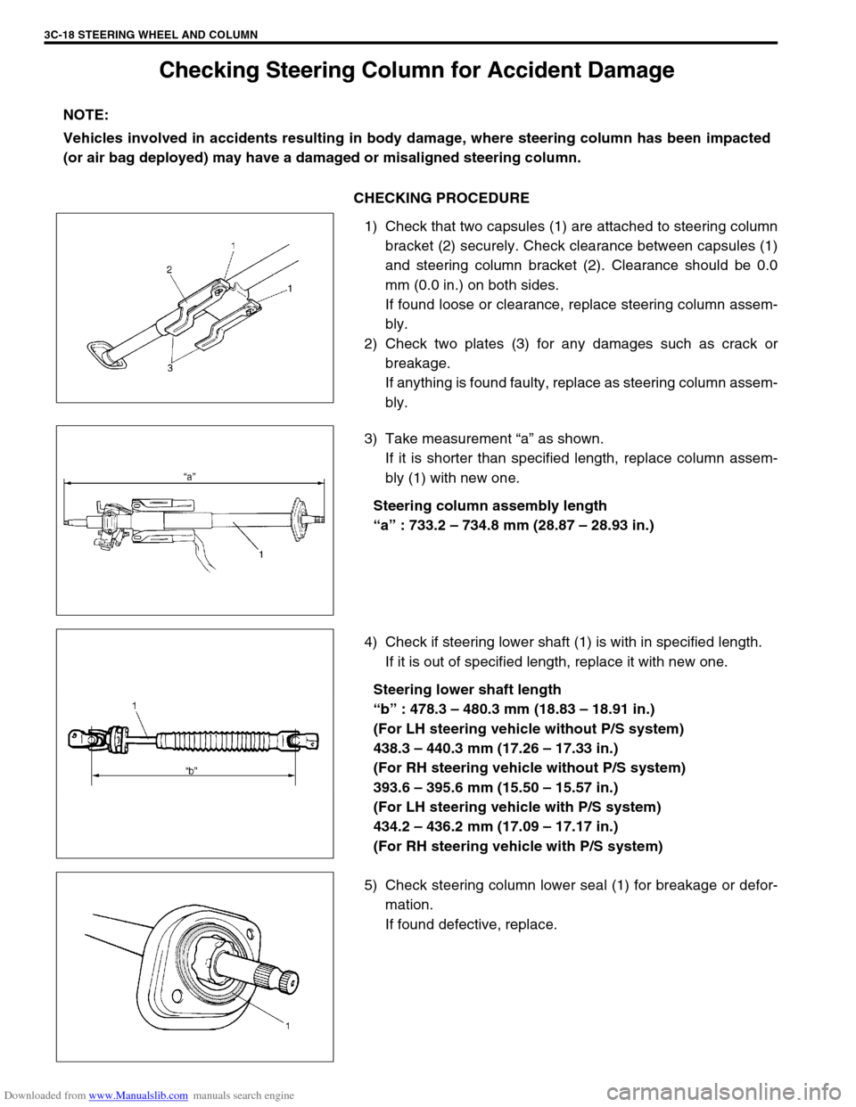
1) Check that two capsules (1) are attached to steering column
bracket (2) securely. Check clearance between capsules (1)
and steering column bracket (2). Clearance should be 0.0
mm (0.0 in.) on both sides.
If found loose or clearance, replace steering column assem-
bly.
2) Check two plates (3) for any damages such as crack or
breakage.
If anything is found faulty, replace as steering column assem-
bly.
3) Take measurement “a” as shown.
If it is shorter than specified length, replace column assem-
bly (1) with new one.
Steering column assembly length
“a” : 733.2 – 734.8 mm (28.87 – 28.93 in.)
4) Check if steering lower shaft (1) is with in specified length.
If it is out of specified length, replace it with new one.
Steering lower shaft length
“b” : 478.3 – 480.3 mm (18.83 – 18.91 in.)
(For LH steering vehicle without P/S system)
438.3 – 440.3 mm (17.26 – 17.33 in.)
(For RH steering vehicle without P/S system)
393.6 – 395.6 mm (15.50 – 15.57 in.)
(For LH steering vehicle with P/S system)
434.2 – 436.2 mm (17.09 – 17.17 in.)
(For RH steering vehicle with P/S system)
5) Check steering column lower seal (1) for breakage or defor-
mation.
If found defective, replace. NOTE:
Vehicles involved in accidents resulting in body damage, where steering column has been impacted
(or air bag deployed) may have a damaged or misaligned steering column.
Page 179 of 687
Downloaded from www.Manualslib.com manuals search engine 3D-6 FRONT SUSPENSION
OPERATION
2WD
→ 4WD
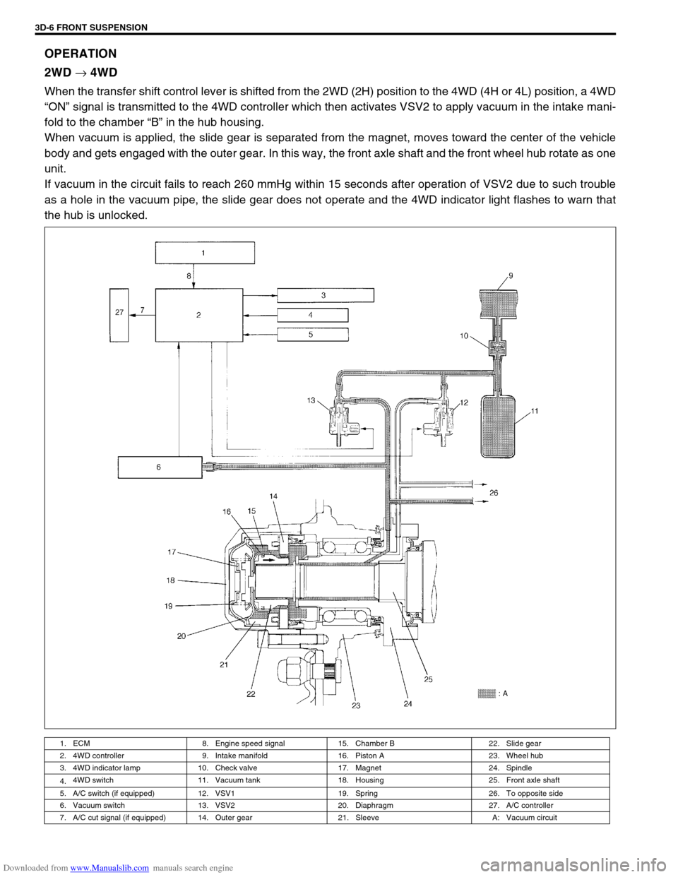
When the transfer shift control lever is shifted from the 2WD (2H) position to the 4WD (4H or 4L) position, a 4WD
“ON” signal is transmitted to the 4WD controller which then activates VSV2 to apply vacuum in the intake mani-
fold to the chamber “B” in the hub housing.
When vacuum is applied, the slide gear is separated from the magnet, moves toward the center of the vehicle
body and gets engaged with the outer gear. In this way, the front axle shaft and the front wheel hub rotate as one
unit.
If vacuum in the circuit fails to reach 260 mmHg within 15 seconds after operation of VSV2 due to such trouble
as a hole in the vacuum pipe, the slide gear does not operate and the 4WD indicator light flashes to warn that
the hub is unlocked.
1. ECM 8. Engine speed signal 15. Chamber B 22. Slide gear
2. 4WD controller 9. Intake manifold 16. Piston A 23. Wheel hub
3. 4WD indicator lamp 10. Check valve 17. Magnet 24. Spindle
4.4WD switch 11. Vacuum tank 18. Housing 25. Front axle shaft
5. A/C switch (if equipped) 12. VSV1 19. Spring 26. To opposite side
6. Vacuum switch 13. VSV2 20. Diaphragm 27. A/C controller
7. A/C cut signal (if equipped) 14. Outer gear 21. Sleeve A: Vacuum circuit
Page 181 of 687

Downloaded from www.Manualslib.com manuals search engine 3D-8 FRONT SUSPENSION
Diagnosis
Diagnosis Table
For description not found in the table below, refer to “Diagnosis Table” in Section 3.
4WD CONTROL SYSTEM
4WD CONTROL SYSTEM DIAGNOSTIC FLOW TABLE
Before performing the trouble diagnosis, check that the air locking hub assemblies are in good condition and
there is no air leakage from vacuum hoses and vacuum pipe. Refer to “4WD Control System Check” in this sec-
tion for air leakage.
[NOTES ON SYSTEM CIRCUIT INSPECTION]
Be sure to read “Precautions for Electrical Circuit Service” in Section 0A before circuit inspection and
observe what is written there.
For system circuit, refer to the figure of “System Circuit” in this section. Condition Possible Cause Correction
4WD Indicator light
flashingHub locking procedure error
Defective VSV2
Defective vacuum switch
Defective check valve or vacuum tank
Air leak from vacuum circuit
Clogged vacuum hose or pipe
Faulty 4WD controllerShift transfer shift control lever
2WD → 4WD once again
Replace
Replace
Replace
Check and repair
Replace
Check and replace
2WD/4WD switching
errorDefective air locking hub assembly
Abnormality in 4WD control system
Air leakage from vacuum circuit
Clogged vacuum hose or pipe
Defective check valve or vacuum tankReplace
Inspect referring to “4WD Control
System Diagnostic Flow Table”
Check and replace
Replace
Replace
Step Action Yes No
1 Check ground circuit.
1) Disconnect coupler from 4WD controller
with ignition switch OFF.
2) Check for proper connection to 4WD con-
troller at all terminals.
3) If OK, check continuity between A5 terminal
and body ground.
Is there continuity between A5 terminal and
body ground?Go to Step 2.“B” wire is open.
2 Check power circuit.
1) Disconnect coupler from 4WD controller.
2) Turn ignition switch ON.
3) Check voltage between A10 terminal and
ground.
Is it 10 – 14 V?Go to Step 3.“Y/R” circuit is open or
short.
Page 183 of 687
Downloaded from www.Manualslib.com manuals search engine 3D-10 FRONT SUSPENSION
4WD Controller and ITS Circuit Check
VOLTAGE CHECK
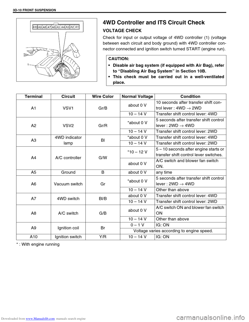
Check for input or output voltage of 4WD controller (1) (voltage
between each circuit and body ground) with 4WD controller con-
nector connected and ignition switch turned START (engine run).
* : With engine runningCAUTION:
Disable air bag system (if equipped with Air Bag), refer
to “Disabling Air Bag System” in Section 10B.
This check must be carried out in a well-ventilated
place.
Terminal Circuit Wire Color Normal Voltage Condition
A1 VSV1 Gr/Babout 0 V10 seconds after transfer shift con-
trol lever : 4WD → 2WD
10 – 14 V Transfer shift control lever: 4WD
A2 VSV2 Gr/R*about 0 V5 seconds after transfer shift control
lever : 2WD → 4WD
10 – 14 V Transfer shift control lever: 2WD
A34WD indicator
lampBl*about 0 V Transfer shift control lever: 4WD
10 – 14 V Transfer shift control lever: 2WD
A4 A/C controller G/W*10 – 12 V5 – 10 seconds after engine starts or
transfer shift control lever switches.
about 0 VA/C switch and blower fan switch
ON.
A5 Ground B about 0 V any time
A6 Vacuum switch Gr*about 0 V5 seconds after transfer shift control
lever : 2WD → 4WD
10 – 14 V Other than above
A7 4WD switch Bl/Babout 0 V Transfer shift control lever: 4WD
10 – 14 V Transfer shift control lever: 2WD
A8 A/C switch G/Babout 0 VA/C switch ON and blower fan switch
ON
10 – 14 V Other than above
A9 Ignition coil Br0 – 1 V IG: ON
Voltage varies according to engine speed.
A10 Ignition switch Y/R 10 – 14 V IG: ON
Page 187 of 687
Downloaded from www.Manualslib.com manuals search engine 3D-14 FRONT SUSPENSION
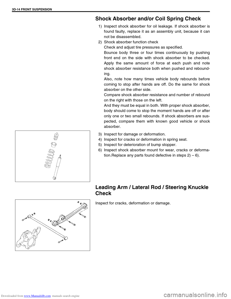
Shock Absorber and/or Coil Spring Check
1) Inspect shock absorber for oil leakage. If shock absorber is
found faulty, replace it as an assembly unit, because it can
not be disassembled.
2) Shock absorber function check
Check and adjust tire pressures as specified.
Bounce body three or four times continuously by pushing
front end on the side with shock absorber to be checked.
Apply the same amount of force at each push and note
shock absorber resistance both when pushed and rebound-
ing.
Also, note how many times vehicle body rebounds before
coming to stop after hands are off. Do the same for shock
absorber on the other side.
Compare shock absorber resistance and number of rebound
on the right with those on the left.
And they must be equal in both. With proper shock absorber,
body should come to stop the moment hands are off or after
only one or two small rebounds. If shock absorbers are sus-
pected, compare them with known good vehicle or shock
absorber.
3) Inspect for damage or deformation.
4) Inspect for cracks or deformation in spring seat.
5) Inspect for deterioration of bump stopper.
6) Inspect shock absorber mount for wear, cracks or deforma-
tion.Replace any parts found defective in steps 2) – 6).
Leading Arm / Lateral Rod / Steering Knuckle
Check
Inspect for cracks, deformation or damage.
Page 206 of 687
Downloaded from www.Manualslib.com manuals search engine FRONT SUSPENSION 3D-33
5) Remove oil seal (1) from axle housing (for 4WD).
6) Drain out kingpin bearing outer race (1) from front axle hous-
ing (2).
INSTALLATION
1) Install kingpin bearing outer race (1) to front axle housing by
using special tools.
Special tool
(A) : 09944-68510
(B) : 09924-74510
2) Press-fit oil seal (1) until it becomes flush with inner surface
of front axle housing (2) by using special tool.
Special tool
(A) : 09951-76010
3) Apply grease to oil seal lip.
“A” : Grease 99000-25010
3. Body center
Page 208 of 687
Downloaded from www.Manualslib.com manuals search engine FRONT SUSPENSION 3D-35
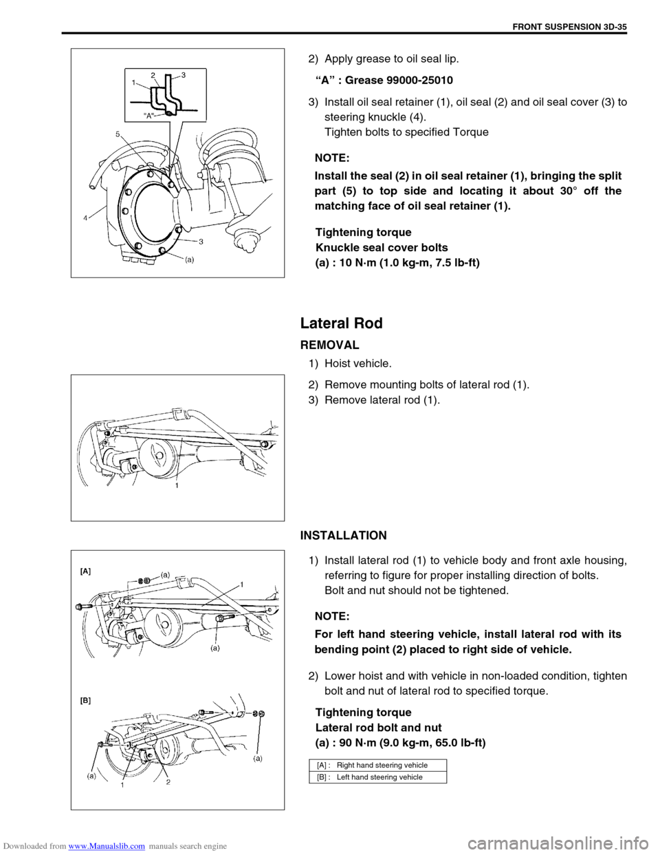
2) Apply grease to oil seal lip.
“A” : Grease 99000-25010
3) Install oil seal retainer (1), oil seal (2) and oil seal cover (3) to
steering knuckle (4).
Tighten bolts to specified Torque
Tightening torque
Knuckle seal cover bolts
(a) : 10 N·m (1.0 kg-m, 7.5 lb-ft)
Lateral Rod
REMOVAL
1) Hoist vehicle.
2) Remove mounting bolts of lateral rod (1).
3) Remove lateral rod (1).
INSTALLATION
1) Install lateral rod (1) to vehicle body and front axle housing,
referring to figure for proper installing direction of bolts.
Bolt and nut should not be tightened.
2) Lower hoist and with vehicle in non-loaded condition, tighten
bolt and nut of lateral rod to specified torque.
Tightening torque
Lateral rod bolt and nut
(a) : 90 N·m (9.0 kg-m, 65.0 lb-ft) NOTE:
Install the seal (2) in oil seal retainer (1), bringing the split
part (5) to top side and locating it about 30° off the
matching face of oil seal retainer (1).
NOTE:
For left hand steering vehicle, install lateral rod with its
bending point (2) placed to right side of vehicle.
[A] : Right hand steering vehicle
[B] : Left hand steering vehicle
Page 210 of 687
Downloaded from www.Manualslib.com manuals search engine FRONT SUSPENSION 3D-37
INSTALLATION
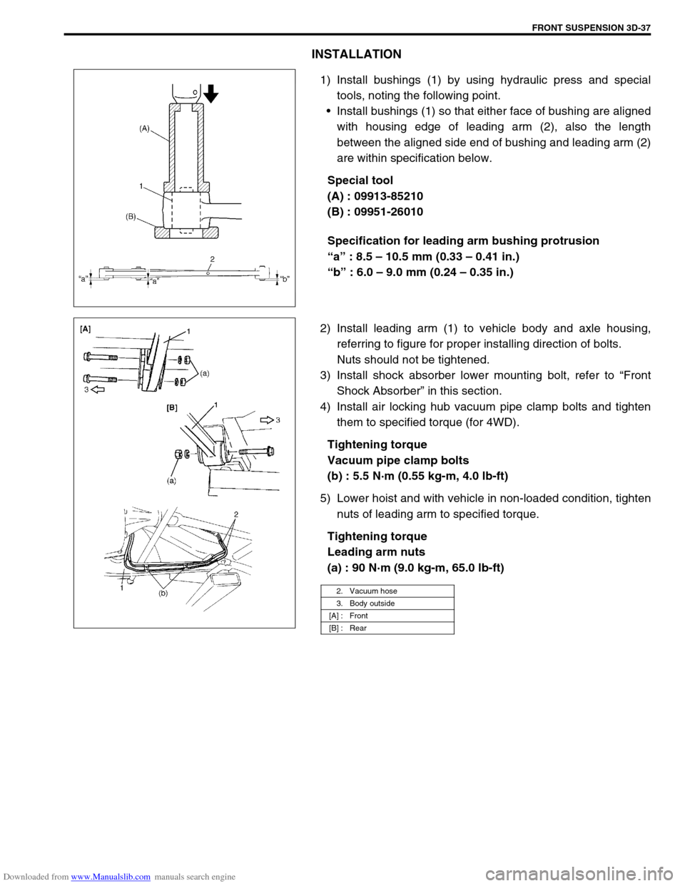
1) Install bushings (1) by using hydraulic press and special
tools, noting the following point.
Install bushings (1) so that either face of bushing are aligned
with housing edge of leading arm (2), also the length
between the aligned side end of bushing and leading arm (2)
are within specification below.
Special tool
(A) : 09913-85210
(B) : 09951-26010
Specification for leading arm bushing protrusion
“a” : 8.5 – 10.5 mm (0.33 – 0.41 in.)
“b” : 6.0 – 9.0 mm (0.24 – 0.35 in.)
2) Install leading arm (1) to vehicle body and axle housing,
referring to figure for proper installing direction of bolts.
Nuts should not be tightened.
3) Install shock absorber lower mounting bolt, refer to “Front
Shock Absorber” in this section.
4) Install air locking hub vacuum pipe clamp bolts and tighten
them to specified torque (for 4WD).
Tightening torque
Vacuum pipe clamp bolts
(b) : 5.5 N·m (0.55 kg-m, 4.0 lb-ft)
5) Lower hoist and with vehicle in non-loaded condition, tighten
nuts of leading arm to specified torque.
Tightening torque
Leading arm nuts
(a) : 90 N·m (9.0 kg-m, 65.0 lb-ft)
2. Vacuum hose
3. Body outside
[A] : Front
[B] : Rear