2005 SUZUKI JIMNY Air bag system
[x] Cancel search: Air bag systemPage 171 of 687

Downloaded from www.Manualslib.com manuals search engine 3C-18 STEERING WHEEL AND COLUMN
Checking Steering Column for Accident Damage
CHECKING PROCEDURE
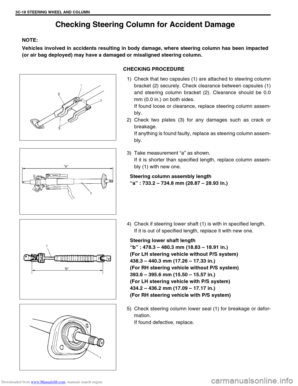
1) Check that two capsules (1) are attached to steering column
bracket (2) securely. Check clearance between capsules (1)
and steering column bracket (2). Clearance should be 0.0
mm (0.0 in.) on both sides.
If found loose or clearance, replace steering column assem-
bly.
2) Check two plates (3) for any damages such as crack or
breakage.
If anything is found faulty, replace as steering column assem-
bly.
3) Take measurement “a” as shown.
If it is shorter than specified length, replace column assem-
bly (1) with new one.
Steering column assembly length
“a” : 733.2 – 734.8 mm (28.87 – 28.93 in.)
4) Check if steering lower shaft (1) is with in specified length.
If it is out of specified length, replace it with new one.
Steering lower shaft length
“b” : 478.3 – 480.3 mm (18.83 – 18.91 in.)
(For LH steering vehicle without P/S system)
438.3 – 440.3 mm (17.26 – 17.33 in.)
(For RH steering vehicle without P/S system)
393.6 – 395.6 mm (15.50 – 15.57 in.)
(For LH steering vehicle with P/S system)
434.2 – 436.2 mm (17.09 – 17.17 in.)
(For RH steering vehicle with P/S system)
5) Check steering column lower seal (1) for breakage or defor-
mation.
If found defective, replace. NOTE:
Vehicles involved in accidents resulting in body damage, where steering column has been impacted
(or air bag deployed) may have a damaged or misaligned steering column.
Page 183 of 687

Downloaded from www.Manualslib.com manuals search engine 3D-10 FRONT SUSPENSION
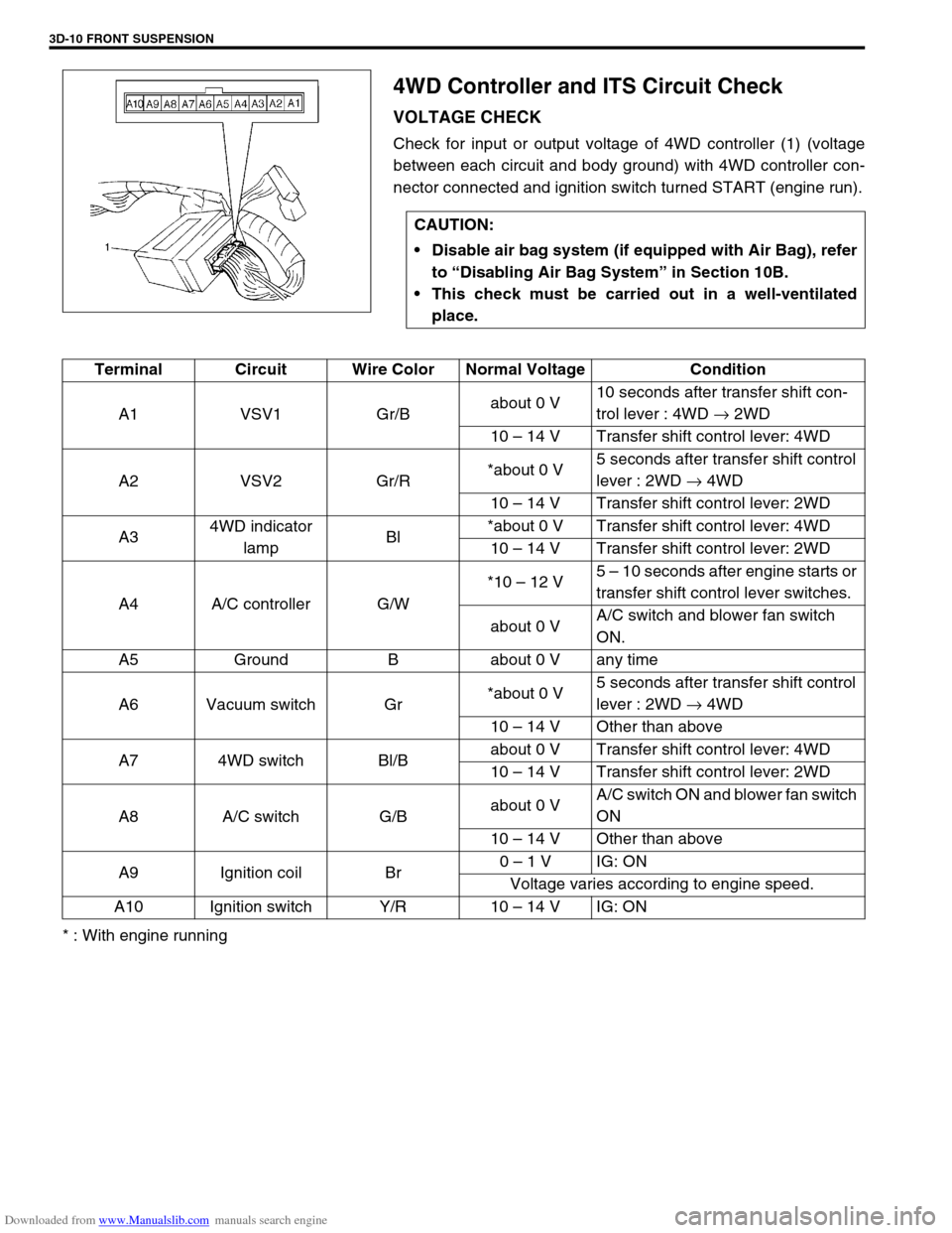
4WD Controller and ITS Circuit Check
VOLTAGE CHECK
Check for input or output voltage of 4WD controller (1) (voltage
between each circuit and body ground) with 4WD controller con-
nector connected and ignition switch turned START (engine run).
* : With engine runningCAUTION:
Disable air bag system (if equipped with Air Bag), refer
to “Disabling Air Bag System” in Section 10B.
This check must be carried out in a well-ventilated
place.
Terminal Circuit Wire Color Normal Voltage Condition
A1 VSV1 Gr/Babout 0 V10 seconds after transfer shift con-
trol lever : 4WD → 2WD
10 – 14 V Transfer shift control lever: 4WD
A2 VSV2 Gr/R*about 0 V5 seconds after transfer shift control
lever : 2WD → 4WD
10 – 14 V Transfer shift control lever: 2WD
A34WD indicator
lampBl*about 0 V Transfer shift control lever: 4WD
10 – 14 V Transfer shift control lever: 2WD
A4 A/C controller G/W*10 – 12 V5 – 10 seconds after engine starts or
transfer shift control lever switches.
about 0 VA/C switch and blower fan switch
ON.
A5 Ground B about 0 V any time
A6 Vacuum switch Gr*about 0 V5 seconds after transfer shift control
lever : 2WD → 4WD
10 – 14 V Other than above
A7 4WD switch Bl/Babout 0 V Transfer shift control lever: 4WD
10 – 14 V Transfer shift control lever: 2WD
A8 A/C switch G/Babout 0 VA/C switch ON and blower fan switch
ON
10 – 14 V Other than above
A9 Ignition coil Br0 – 1 V IG: ON
Voltage varies according to engine speed.
A10 Ignition switch Y/R 10 – 14 V IG: ON
Page 262 of 687

Downloaded from www.Manualslib.com manuals search engine BRAKES 5-1
6F1
6F2
6G
6H
6K
7A
7A1
7B1
7C1
7D
7E
5
9
10
10A
10B
9
10
10A
10B
SECTION 5
BRAKES
CONTENTS
General Description ......................................... 5-3
Diagnosis .......................................................... 5-4
Road Testing Brakes ...................................... 5-4
Brake Fluid Leaks .......................................... 5-4
Substandard or Contaminated Brake Fluid .... 5-4
Diagnosis Table ............................................. 5-5
Brake Pedal Free Height Adjustment ............. 5-8
Brake Pedal Play Check ................................ 5-8
Stop Light Switch Adjustment ........................ 5-8
Excessive Pedal Travel Check ....................... 5-9
Front Brake Disc Check ................................. 5-9
Front Brake Pad Check .................................. 5-9
Rear Brake Shoe Check .............................. 5-10
Master Cylinder and Brake Fluid Level
Check ........................................................... 5-10
Rear Drum Brake Shoe Adjustment ............. 5-11
Parking Brake Inspection and Adjustment ... 5-11
Booster Operation Check ............................. 5-12Fluid Pressure Test
(If Equipped with LSPV) ............................... 5-15
On-Vehicle Service ........................................ 5-17
Air Bleeding of Brake System ...................... 5-17
Brake Hose and Pipe Inspection.................. 5-18
Front Disc Brake .......................................... 5-19
Brake pad ................................................. 5-20
Caliper assembly...................................... 5-22
Brake Disc.................................................... 5-26
Rear Brake ................................................... 5-29
Brake drum............................................... 5-29
Brake shoe ............................................... 5-32
Wheel Cylinder............................................. 5-33
Brake back plate ...................................... 5-34
Master Cylinder .............................................. 5-36
Master Cylinder Reservoir ........................... 5-36
Master Cylinder Assembly ........................... 5-37 WARNING:
For lifting point of vehicle, refer to Section 0A.
WARNING:
For vehicles equipped with Supplement Restraint (Air Bag) System:
Service on and around the air bag system components or wiring must be performed only by an
authorized SUZUKI dealer. Refer to “Air Bag System Components and Wiring Location View” under
“General Description” in air bag system section in order to confirm whether you are performing ser-
vice on or near the air bag system components or wiring. Please observe all WARNINGS and “Ser-
vice Precautions” under “On-Vehicle Service” in air bag system section before performing service
on or around the air bag system components or wiring. Failure to follow WARNINGS could result in
unintentional activation of the system or could render the system inoperative. Either of these two
conditions may result in severe injury.
Technical service work must be started at least 90 seconds after the ignition switch is turned to the
“LOCK” position and the negative cable is disconnected from the battery. Otherwise, the system
may be activated by reserve energy in the Sensing and Diagnostic Module (SDM).
NOTE:
When inspecting and servicing vehicle equipped with ABS, be sure to refer to section 5E first.
All brake fasteners are important attaching parts in that they could affect the performance of vital
parts and systems, and/or could result in major repair expense. They must be replaced with one of
same part number or with an equivalent part if replacement becomes necessary. Do not use a
replacement part of lesser quality or substitute design. Torque values must be used as specified
during reassembly to assure proper retention of all parts. There is to be no welding as it may result
in extensive damage and weakening of the metal.
Page 358 of 687

Downloaded from www.Manualslib.com manuals search engine ENGINE GENERAL INFORMATION AND DIAGNOSIS 6-1
6F2
6G
6H
6K
7A
7A1
7B1
7C1
7D
7E
7F
8B
6
8D
8E
8B
9
10A
10B
SECTION 6
ENGINE GENERAL INFORMATION AND
DIAGNOSIS
GENERAL INFORMATION AND ENGINE DIAGNOSIS ..............................................................................
6-1
ENGINE MECHANICAL ...........................................................................................................................
6A1-1
ENGINE COOLING.....................................................................................................................................
6B-1
ENGINE FUEL ............................................................................................................................................
6C-1
ENGINE AND EMISSION CONTROL SYSTEM ........................................................................................
6E-1
IGNITION SYSTEM ....................................................................................................................................
6F-1
CRANKING SYSTEM .................................................................................................................................
6G-1
CHARGING SYSTEM .................................................................................................................................
6H-1
EXHAUST SYSTEM ...................................................................................................................................
6K-1
CONTENTS
General Information .......................................... 6-3
Statement on Cleanliness and Care ............... 6-3
General Information on Engine Service .......... 6-3
Precaution on fuel system service............... 6-4
Fuel pressure relief procedure .................... 6-5
Fuel leakage check procedure .................... 6-5
Engine Diagnosis .............................................. 6-6
General Description ........................................ 6-6
On-Board Diagnostic System (Vehicle with
Immobilizer Indicator Lamp) ............................ 6-6On-Board Diagnostic System (Vehicle without
Immobilizer Indicator Lamp)............................ 6-9
Precaution in Diagnosing Trouble ................. 6-10
Engine Diagnostic Flow Table ...................... 6-11
Customer problem inspection form
(example) .................................................. 6-13
Malfunction indicator lamp (MIL) check..... 6-14
Diagnostic trouble code (DTC) check ....... 6-14
Diagnostic trouble code (DTC)
clearance................................................... 6-15 WARNING:
For vehicles equipped with Supplemental Restraint (Air Bag) System :
Service on and around the air bag system components or wiring must be performed only by an
authorized SUZUKI dealer. Refer to “Air Bag System Components and Wiring Location View” under
“General Description” in air bag system section in order to confirm whether you are performing ser-
vice on or near the air bag system components or wiring. Please observe all WARNINGS and “Ser-
vice Precautions” under “On-Vehicle Service” in air bag system section before performing service
on or around the air bag system components or wiring. Failure to follow WARNINGS could result in
unintentional activation of the system or could render the system inoperative. Either of these two
conditions may result in severe injury.
Technical service work must be started at least 90 seconds after the ignition switch is turned to the
“LOCK” position and the negative cable is disconnected from the battery. Otherwise, the system
may be activated by reserve energy in the Sensing and Diagnostic Module (SDM).
NOTE:
Whether the following systems (parts) are used in the particular vehicle or not depends on vehicle
specifications. Be sure to bear this in mind when performing service work.
EGR valve
Heated oxygen sensor(s) or CO adjusting resistor
Three-way catalytic converter (TWC) and warm up three-way catalytic converter (WU-TWC)
Page 482 of 687

Downloaded from www.Manualslib.com manuals search engine ENGINE MECHANICAL (M13 ENGINE) 6A1-1
6F1
6G
6H
6K
7A
7A1
7B1
7C1
7D
7E
7F
8A
8C
6A1
8E
9
9
10B
SECTION 6A1
ENGINE MECHANICAL (M13 ENGINE)
CONTENTS
General Description ......................................6A1-2
Engine ......................................................... 6A1-2
Engine Lubrication ...................................... 6A1-3
Diagnosis .......................................................6A1-4
Diagnosis Table .......................................... 6A1-4
Compression Check .................................... 6A1-4
Engine Vacuum Check ................................ 6A1-6
Oil Pressure Check ..................................... 6A1-7
Valve Lash (Clearance) ............................... 6A1-9
On-Vehicle Service......................................6A1-13
Air Cleaner Element .................................. 6A1-13
Air Cleaner Assembly ................................ 6A1-14
Knock Sensor ............................................ 6A1-14
Cylinder Head Cover ................................. 6A1-15
Throttle Body and Intake Manifold ............ 6A1-18
Exhaust Manifold ....................................... 6A1-21Oil Pan and Oil Pump Strainer .................. 6A1-24
Timing Chain Cover .................................. 6A1-28
Oil Pump ................................................... 6A1-33
Timing Chain and Chain Tensioner .......... 6A1-37
Camshaft, Tappet and Shim ..................... 6A1-42
Valves and Cylinder Head ........................ 6A1-48
Pistons, Piston Rings, Connecting
Rods and Cylinders................................... 6A1-62
Engine Mountings ..................................... 6A1-72
Unit Repair Overhaul .................................. 6A1-73
Engine Assembly ...................................... 6A1-73
Main Bearings, Crankshaft and Cylinder
Block ......................................................... 6A1-79
Required Service Material .......................... 6A1-93
Tightening Torque Specification ............... 6A1-93
Special Tool ................................................. 6A1-94
WARNING:
For vehicles equipped with Supplemental Restraint (Air Bag) System:
Service on and around the air bag system components or wiring must be performed only by an
authorized SUZUKI dealer. Refer to “Air Bag System Components and Wiring Location View” under
“General Description” in air bag system section in order to confirm whether you are performing ser-
vice on or near the air bag system components or wiring. Please observe all WARNINGS and “Ser-
vice Precautions” under “On-Vehicle Service” in air bag system section before performing service
on or around the air bag system components or wiring. Failure to follow WARNINGS could result in
unintentional activation of the system or could render the system inoperative. Either of these two
conditions may result in severe injury.
Technical service work must be started at least 90 seconds after the ignition switch is turned to the
“LOCK” position and the negative cable is disconnected from the battery. Otherwise, the system
may be activated by reserve energy in the Sensing and Diagnostic Module (SDM).
Page 606 of 687

Downloaded from www.Manualslib.com manuals search engine ENGINE AND EMISSION CONTROL SYSTEM 6E-1
6F1
6F2
6G
7C1
7D
7E
7A
7A1
7B1
7C1
7D
7E
7F
8A
8B
8C
8D
6H
6E
10
10A
10B
SECTION 6E
ENGINE AND EMISSION CONTROL SYSTEM
CONTENTS
General Description ....................................... 6E-3
Air Intake System ......................................... 6E-5
Fuel Delivery System ................................... 6E-6
Fuel pump ................................................ 6E-6
Electronic Control System ............................ 6E-7
Engine & emission control input / output
table.......................................................... 6E-8
On-Vehicle Service....................................... 6E-15
Accelerator cable adjustment ................. 6E-15
Idle speed / idle air control (IAC) duty
inspection ............................................... 6E-15
Idle mixture inspection / adjustment
(vehicle without heated oxygen
sensor) ................................................... 6E-17
Air Intake System ....................................... 6E-18
Throttle body .......................................... 6E-18
Idle air control valve (IAC valve)............. 6E-21
Fuel Delivery System ................................. 6E-22
Fuel pressure inspection ........................ 6E-22
Fuel pump .............................................. 6E-23
Fuel pressure regulator .......................... 6E-24
Fuel injector ............................................ 6E-25
Electronic Control System .......................... 6E-29Engine control module (ECM) ................ 6E-29
Manifold absolute pressure sensor (MAP
sensor) ................................................... 6E-29
Throttle position sensor (TP sensor) ...... 6E-30
Intake air temperature sensor
(IAT sensor) ........................................... 6E-31
Engine coolant temperature sensor
(ECT sensor) .......................................... 6E-32
Heated oxygen sensor
(Sensor-1 and sensor-2) ........................ 6E-33
Camshaft position sensor....................... 6E-34
Crankshaft position sensor..................... 6E-35
Vehicle speed sensor (VSS) .................. 6E-36
Fuel level sensor (GAUGE).................... 6E-36
Knock sensor ......................................... 6E-36
Main relay, fuel pump relay and A/C
condenser fan control relay .................... 6E-36
Fuel cut operation .................................. 6E-37
A/C condenser fan control system ......... 6E-37
A/C condenser fan ................................. 6E-37
Output signals of throttle valve opening
and engine coolant temp.
(Vehicle with A/T only) ........................... 6E-38
Emission Control System ........................... 6E-38 WARNING:
For vehicles equipped with Supplemental Restraint (Air Bag) System:
Service on and around the air bag system components or wiring must be performed only by an
authorized SUZUKI dealer. Refer to “Air Bag System Components and Wiring Location View” under
“General Description” in air bag system section in order to confirm whether you are performing ser-
vice on or near the air bag system components or wiring. Please observe all WARNINGS and “Ser-
vice Precautions” under “On-Vehicle Service” in air bag system section before performing service
on or around the air bag system components or wiring. Failure to follow WARNINGS could result in
unintentional activation of the system or could render the system inoperative. Either of these two
conditions may result in severe injury.
Technical service work must be started at least 90 seconds after the ignition switch is turned to the
“LOCK” position and the negative cable is disconnected from the battery. Otherwise, the system
may be activated by reserve energy in the Sensing and Diagnostic Module (SDM).
NOTE:
Whether following systems (parts) are used in the particular vehicle or not depends on specifications.
Be sure to bear this in mind when performing service work.
EGR valve
Heated oxygen sensor (s) or CO adjusting resistor
Three way catalytic converter (TWC) and warm up three-way catalytic converter (WU-TWC)
Page 634 of 687

Downloaded from www.Manualslib.com manuals search engine ENGINE AND EMISSION CONTROL SYSTEM 6E-29
Electronic Control System
Engine control module (ECM)
REMOVAL
1) Disconnect battery negative cable at battery.
2) Disable air bag system, refer to “Disabling Air Bag System”
in Section 10B if equipped.
3) Remove glove box.
4) Disconnect ECM (1) and TCM (3) (if equipped) connectors.
5) Loosen 2 nuts (2) and remove ECM and TCM (if equipped).
INSTALLATION
1) Reverse removal procedure noting the following:
Connect connectors to ECM and TCM (if equipped)
securely.
Manifold absolute pressure sensor (MAP sensor)
INSPECTION
Check MAP sensor referring to “MAP Sensor Individual Check” in
DTC P0105 (No.11) Flow Table of Section 6. If malfunction is
found, replace.CAUTION:
As ECM consists of precision parts, be careful not to
expose it to excessive shock.
Page 650 of 687

Downloaded from www.Manualslib.com manuals search engine IGNITION SYSTEM (ELECTRONIC IGNITION SYSTEM) 6F-1
6G
6F2
6G
6H
7D
7E
7F
7A1
7A1
7D
7E
7F
8A
8B
8C
8D
8E
6K
6F
7A
10
10A
10B
SECTION 6F
IGNITION SYSTEM
(ELECTRONIC IGNITION SYSTEM)
CONTENTS
General Description ........................................ 6F-2
Diagnosis ......................................................... 6F-3
On-Vehicle Service.......................................... 6F-5
Ignition Spark Test ........................................ 6F-5
High-tension Cords ....................................... 6F-5
Spark Plugs ................................................... 6F-6Ignition Coil Assembly (Including Ignitor) ...... 6F-7
Crankshaft Position Sensor (CKP Sensor) ... 6F-8
Ignition Timing............................................... 6F-8
Special Tools ................................................. 6F-10
Tightening Torque Specification ................. 6F-10
WARNING:
For vehicles equipped with Supplemental Restraint (Air Bag) System:
Service on and around the air bag system components or wiring must be performed only by an
authorized SUZUKI dealer. Refer to “Air Bag System Components and Wiring Location View” under
“General Description” in air bag system section in order to confirm whether you are performing ser-
vice on or near the air bag system components or wiring. Please observe all WARNINGS and “Ser-
vice Precautions” under “On-Vehicle Service” in air bag system section before performing service
on or around the air bag system components or wiring. Failure to follow WARNINGS could result in
unintentional activation of the system or could render the system inoperative. Either of these two
conditions may result in severe injury.
Technical service work must be started at least 90 seconds after the ignition switch is turned to the
“LOCK” position and the negative cable is disconnected from the battery. Otherwise, the system
may be activated by reserve energy in the Sensing and Diagnostic Module (SDM).