Page 675 of 687

Downloaded from www.Manualslib.com manuals search engine 6H-8 CHARGING SYSTEM
UNDERCHARGED BATTERY
This condition, as evidenced by slow cranking or indicator clear
with red dot can be caused by one or more of the following condi-
tions even though indicator lamp may be operating normal.
Following procedure also applies to cars with voltmeter and
ammeter.
1) Make sure that undercharged condition has not been caused
by accessories left on for extended period of time.
2) Check drive belt for proper tension.
3) If battery defect is suspected, refer to BATTERY section.
4) Inspect wiring for defects. Check all connections for tight-
ness and cleanliness, battery cable connections at battery,
starting motor and ignition ground cable.
5) Connect voltmeter and ammeter as shown in the figure.
6) Measure current and voltage.
No-load Check
1) Run engine from idling up to 2,000 rpm and read meters.
Standard current
10 A maximum
Standard voltage
14.4 – 15.0 V (at 20 °C, 68 °F)
Higher Voltage
If voltage is higher than standard value, check ground of brushes.
If brushes are not grounded, replace IC regulator.
Lower Voltage
If voltage is below or in standard value, increase engine speed up
to 2,000 – 2,500 rpm soon after starting engine, and read maxi-
mum value on ammeter immediately.
If current is less than 49 A, repair or replace generator.NOTE:
Use fully charged battery.
1. Generator
2. Ammeter (between generator (B) terminal and battery (+) terminal)
3. Voltmeter (between generator (B) terminal and ground)
4. Battery
5. Load
6. Switch
NOTE:
Turn off switches of all accessories (wiper, heater etc.).
NOTE:
Consideration should be taken that voltage will differ
somewhat with regulator case temperature as shown in
the graph.
Page 676 of 687

Downloaded from www.Manualslib.com manuals search engine CHARGING SYSTEM 6H-9
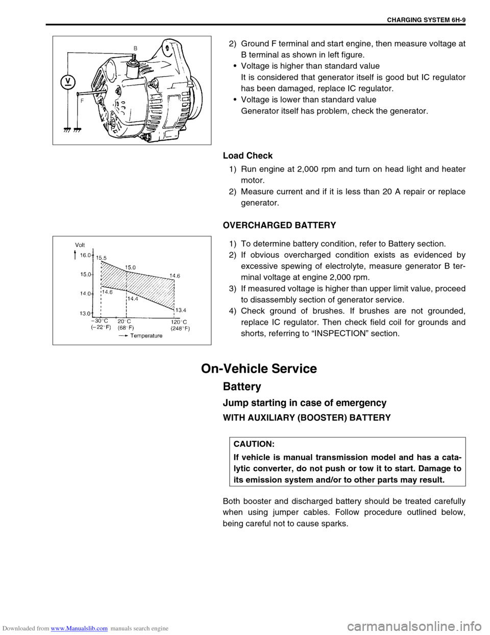
2) Ground F terminal and start engine, then measure voltage at
B terminal as shown in left figure.
Voltage is higher than standard value
It is considered that generator itself is good but IC regulator
has been damaged, replace IC regulator.
Voltage is lower than standard value
Generator itself has problem, check the generator.
Load Check
1) Run engine at 2,000 rpm and turn on head light and heater
motor.
2) Measure current and if it is less than 20 A repair or replace
generator.
OVERCHARGED BATTERY
1) To determine battery condition, refer to Battery section.
2) If obvious overcharged condition exists as evidenced by
excessive spewing of electrolyte, measure generator B ter-
minal voltage at engine 2,000 rpm.
3) If measured voltage is higher than upper limit value, proceed
to disassembly section of generator service.
4) Check ground of brushes. If brushes are not grounded,
replace IC regulator. Then check field coil for grounds and
shorts, referring to “INSPECTION” section.
On-Vehicle Service
Battery
Jump starting in case of emergency
WITH AUXILIARY (BOOSTER) BATTERY
Both booster and discharged battery should be treated carefully
when using jumper cables. Follow procedure outlined below,
being careful not to cause sparks.
CAUTION:
If vehicle is manual transmission model and has a cata-
lytic converter, do not push or tow it to start. Damage to
its emission system and/or to other parts may result.
Page 677 of 687

Downloaded from www.Manualslib.com manuals search engine 6H-10 CHARGING SYSTEM
1) Set parking brake and place automatic transmission in
PARK (NEUTRAL on manual transmission). Turn off ignition,
turn off lights and all other electrical loads.
2) Check electrolyte level. If it is below low level line, add dis-
tilled water.
3) Attach end of one jumper cable to positive terminal of
booster battery and the other end of the same cable to posi-
tive terminal of discharged battery. (Use 12-volt battery only
to jump start engine).
4) Attach one end of the remaining negative cable to negative
terminal of booster battery, and the other end to a solid
engine ground (such as exhaust manifold) at least 45 cm (18
in.) away from battery of vehicle being started.
5) Start engine of vehicle with booster battery and turn off elec-
trical accessories. Then start engine of the vehicle with dis-
charged battery.
6) Disconnect jumper cables in the exact reverse order.
WITH CHARGING EQUIPMENT
WARNING:
Departure from these conditions or procedure
described below could result in:
–Serious personal injury (particularly to eyes) or
property damage from such causes as battery explo-
sion, battery acid, or electrical burns.
–Damage to electronic components of either vehicle.
Remove rings, watches, and other jewelry. Wear
approved eye protection.
Be careful so that metal tools or jumper cables do not
contact positive battery terminal (or metal in contact
with it) and any other metal on vehicle, because a short
circuit could occur.
WARNING:
Do not connect negative cable directly to negative termi-
nal of dead battery.
CAUTION:
When jump starting engine with charging equipment, be
sure equipment used is 12-volt and negative ground. Do
not use 24-volt charging equipment. Using such equip-
ment can cause serious damage to electrical system or
electronic parts.
Page 678 of 687
Downloaded from www.Manualslib.com manuals search engine CHARGING SYSTEM 6H-11
Dismounting
1) Disconnect negative cable (3).
2) Disconnect positive cable (2).
3) Remove retainer (5).
4) Remove battery (1).
Handling
When handling battery, following safety precautions should be
followed:
Hydrogen gas is produced by battery. A flame or spark near
battery may cause the gas to ignite.
Battery fluid is highly acidic. Avoid spilling on clothing or
other fabric. Any spilled electrolyte should be flushed with
large quantity of water and cleaned immediately.
Remounting
1) Reverse removal procedure.
2) Torque battery cables to specification.
Tightening torque
Body ground bolt (a) : 8.0 N·m (0.8 kg-m, 6.0 lb-ft)
Generator
Generator belt
Refer to “Water Pump Belt and Cooling Fan” in Section 6B.
4. Body ground bolt
NOTE:
Check to be sure that ground cable has enough clear-
ance to hood panel by terminal.
Page 681 of 687
Downloaded from www.Manualslib.com manuals search engine 6H-14 CHARGING SYSTEM
Inspection
Rotor
1) Using ohmmeter, check for continuity between slip rings of
rotor (1). If there is no continuity, replace rotor.
Standard resistance between slip rings of rotor
1.8 – 2.1
Ω
ΩΩ Ω
2) Using ohmmeter, check that there is no continuity between
slip ring and rotor core. If there is continuity, replace rotor.
3) Check slip rings for roughness or scoring. If rough or scored,
replace rotor (1).
4) Check slip rings for roughness or scoring. If rough or scored,
replace rotor.
Using a vernier caliper, measure the slip ring diameter.
If the diameter is less than minimum, replace the rotor.
Slip ring diameter
Standard : 14.4 mm (0.567 in.)
Limit : 14.0 mm (0.551 in.)
Stator
1) Using ohmmeter, check all leads for continuity.
If there is no continuity, replace stator (1).
Page 682 of 687
Downloaded from www.Manualslib.com manuals search engine CHARGING SYSTEM 6H-15
2) Using ohmmeter, check that there is no continuity between
coil leads (2) and stator core. If there is continuity, replace
stator (1).
Brush and Brush Holder
Check each brush for wear by measuring its length.
If brush is found worn down to service limit, replace brush.
Brush length “a”
Standard : 16 mm (0.63 in.)
Service limit : 2 mm (0.08 in.)
Rectifier
1) Using ohmmeter, check continuity between each of upper
and lower rectifier bodies and each diode lead (2).
Check both directions by reversing probes of ohmmeter and
there should be only one-way continuity in each case.
If check result is not satisfactory, replace rectifier (1).
Page 683 of 687
Downloaded from www.Manualslib.com manuals search engine 6H-16 CHARGING SYSTEM
Drive End Bearing
Check that the bearing is not rough or worn.
End Housing Bearing
Check that the bearing is not rough or worn.
When removal is necessary, use bearing puller to remove end
housing bearing (1).
Replace Brush
1) Unsolder and remove the brush and spring.
2) Run the wire of a new brush through the spring and the hole
in the brush holder, and insert the spring and brush into the
brush holder.
3) Solder the brush wire to the brush holder at specified
exposed length.
Exposed brush length
“a” : 10.5 mm (0.413 in.)
4) Check that the brush moves smoothly in the brush holder.
5) Cut off the excess wire.
6) Apply insulation paint to the soldered area.
CAUTION:
Be careful not to distort cooling fan blade while applying
puller.
Page 686 of 687

Downloaded from www.Manualslib.com manuals search engine EXHAUST SYSTEM 6K-1
6F1
6F2
6G
6H
7D
7E
7F
7D
7E
7F
8A
8B
8C
8D
8E
9
7A1
6K
7C1
SECTION 6K
EXHAUST SYSTEM
CONTENTS
General Description ........................................6K-1
Maintenance ....................................................6K-1On-Vehicle Service ......................................... 6K-2
Exhaust Manifold .......................................... 6K-2
Exhaust Pipe ................................................. 6K-2
General Description
The exhaust system of this vehicle consists of the exhaust manifold, exhaust center pipe, muffler, seals, etc.
The catalytic converter is an emission control device added to the exhaust system to lower the level of Hydro-
carbon (HC), Carbon Monoxide (CO) and Oxides of Nitrogen (NOx) pollutants in the exhaust gas. The catalyst
in the catalytic converter is of “Three way” type.
Maintenance
At every interval of periodic maintenance service, and when vehicle is raised for other service, check exhaust
system as follows:
Check rubber mountings for damage, deterioration and out of position.
Check exhaust system for leakage, loose connection, dent and damage.
If bolts or nuts are loosened, tighten them to specified torque. Refer to “Components” in this section.
Check nearby body areas for damaged, missing, or mispositioned part, open seam, hole, loose connection
or any other defect which could permit exhaust fumes to seep into vehicle.
Make sure that exhaust system components have enough clearance from underbody to avoid overheating
and possible damage to passenger compartment carpet.
Any defect should be fixed at once. NOTE:
Whether following parts are used in the particular vehicle or not depends on specification. Be sure to
bear this in mind when performing service work.
Three-Way Catalytic Converter (TWC)
CAUTION:
Be sure to use UNLEADED FUEL for the catalytic converter equipped vehicle. Use of LEADED FUEL
will affect performance of the catalytic converter adversely to a great extent.
WARNING:
To avoid danger of being burned, do not touch exhaust system when system is hot.
Any service on exhaust system should be performed when system is cool.