2005 SUZUKI JIMNY lock
[x] Cancel search: lockPage 114 of 687

Downloaded from www.Manualslib.com manuals search engine STEERING, SUSPENSION, WHEELS AND TIRES 3-5
Tire Diagnosis
Irregular and/or Premature Wear
Irregular and premature wear has many possible causes. Some
of them are: incorrect inflation pressures lack of tire rotation, driv-
ing habits, improper alignment.
If the following conditions are noted rotation is in order:
Front tire wear is different from rear.
Uneven wear exists across the tread of any tire.
Left front and right front tire wear is unequal.
Left rear and right rear tire wear is unequal.
There is cupping, flat spotting, etc.
A wheel alignment check is in order if the following conditions are
noted:
Left front and right front tire wear is unequal.
Wear is uneven across the tread of any front tire.
Front tire treads have scuffed appearance with “feather”
edges on one side of tread ribs or blocks.
Wear Indicators
The original equipment tires have built-in tread wear indicators to
show when tires need replacement. These indicators will appear
as 12 mm (0.47 inch) wide bands when the tire tread depth
becomes 1.6 mm (0.063 inch). When the indicators appear in 3 or
more grooves at 6 locations, tire replacement is recommended.
Radial Tire Waddle
Waddle is side to side movement at the front and/or rear of the
vehicle. It is caused by the steel belt not being straight within the
tire. It is most noticeable at low speed, 5 to 30 mph. It is possible
to road test a vehicle and tell on which end of the vehicle the
faulty tire is located. If the waddle tire is on the rear, the rear end
of the vehicle will shake from side to side or “waddle”. From the
driver’s seat it feels as though someone is pushing on the side of
the vehicle. If the faulty tire is on the front, the waddle is more
visual. The front sheet metal appears to be moving back and forth
and the driver feels as though he is at the pivot point in the vehi-
cle. Waddle can be quickly diagnosed by using a Tire Problem
Detector (TPD) and following the equipment manufacturer’s rec-
ommendations.
If a TPD is not available, the more time consuming method of sub-
stituting known good tire / wheel assemblies on the problem vehi-
cle can be used as follows:
[A] : Hard cornering, under inflation or lack of tire rotation
[B] : Incorrect wheel alignment, tire construction not uniform or wheel heavy acceleration
Page 120 of 687

Downloaded from www.Manualslib.com manuals search engine FRONT WHEEL ALIGNMENT 3A-3
Diagnosis
Diagnosis Table
For the details, refer to “Diagnosis Table” in Section 3.
Preliminary Checks Prior To Adjusting Front Wheel Alignment
Steering and vibration complaints are not always the result of improper alignment. An additional item to be
checked is the possibility of tire lead due to worn or improperly manufactured tires. “Lead” is the deviation of the
vehicle from a straight path on a level road without hand pressure on the steering wheel. Section 3 of this man-
ual contains a procedure for determining the presence of a tire lead problem. Before making any adjustment
affecting toe setting, the following checks and inspections should be made to ensure correctness of alignment
readings and alignment adjustments:
1) Check all tires for proper inflation pressures and approximately the same tread wear.
2) Check for loose of king pin bearings. Check tie rod ends; if excessive looseness is noted, it must be cor-
rected before adjusting.
3) Check for run-out of wheels and tires.
4) Check vehicle trim heights; if out of limits and a correction is to be made, it must be made before adjusting
toe.
5) Check for loose of suspension arms.
6) Check for loose or missing stabilizer bar attachments.
7) Consideration must be given to excess loads, such as tool boxes. If this excess load is normally carried in
vehicle, it should remain in vehicle during alignment checks.
8) Consider condition of equipment being used to check alignment and follow manufacturer's instructions.
9) Regardless of equipment used to check alignment, vehicle must be on a level surface both fore and aft and
transversely.
Toe Adjustment
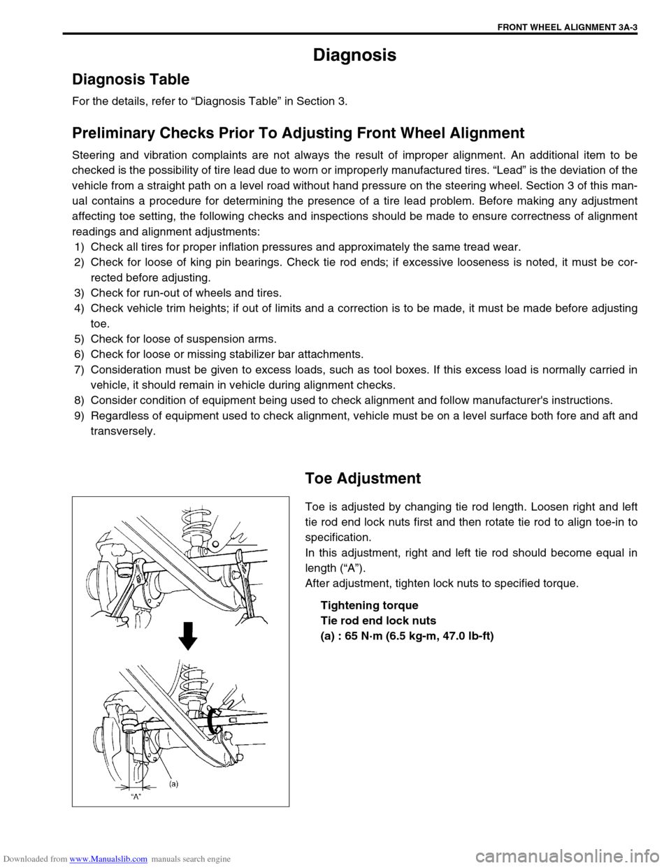
Toe is adjusted by changing tie rod length. Loosen right and left
tie rod end lock nuts first and then rotate tie rod to align toe-in to
specification.
In this adjustment, right and left tie rod should become equal in
length (“A”).
After adjustment, tighten lock nuts to specified torque.
Tightening torque
Tie rod end lock nuts
(a) : 65 N·m (6.5 kg-m, 47.0 lb-ft)
Page 122 of 687

Downloaded from www.Manualslib.com manuals search engine STEERING GEAR BOX (MANUAL TYPE) AND LINKAGE 3B-1
6F1
6F2
6G
6H
3B
7C1
7D
7E
7D
7E
7F
8A
8B
8C
8D
8E
9
10
10A
10B
SECTION 3B
STEERING GEAR BOX (MANUAL TYPE)
AND LINKAGE
CONTENTS
General Description ....................................... 3B-2
Diagnosis ........................................................ 3B-3
Diagnosis Table ........................................... 3B-3
Steering Wheel Play Check ......................... 3B-3
Tie Rod And Drag Rod Check ...................... 3B-3
Steering Gear Box Oil Level Check ............. 3B-4
Adjustment of Worm Shaft Starting Torque . 3B-4On-Vehicle Service ........................................ 3B-6
Steering Gear Box ....................................... 3B-6
Tie Rod And Drag Rod................................. 3B-8
Tightening Torque Specifications .............. 3B-10
Required Service Material ........................... 3B-10
Special Tools ................................................ 3B-10 WARNING:
For vehicles equipped with Supplemental Restraint (Air Bag) System
Service on and around the air bag system components or wiring must be performed only by an
authorized SUZUKI dealer. Refer to “Air Bag System Components and Wiring Location View” under
“General Description” in air bag system section in order to confirm whether you are performing ser-
vice on or near the air bag system components or wiring. Please observe all WARNINGS and “Ser-
vice Precautions” under “On-Vehicle Service” in air bag system section before performing service
on or around the air bag system components or wiring. Failure to follow WARNINGS could result in
unintentional activation of the system or could render the system inoperative. Either of these two
conditions may result in severe injury.
Technical service work must be started at least 90 seconds after the ignition switch is turned to the
“LOCK” position and negative cable is disconnected from the battery. Otherwise, the system may
be activated by reserve energy in the Sensing and Diagnostic Module (SDM)
NOTE:
All steering gear fasteners are important attaching parts in that they could affect the performance of
vital parts and systems, and/or could result in major repair expense. They must be replaced with one
of the same part number or with an equivalent part if replacement becomes necessary. Do not use a
replacement part of lesser quality or substitute design. Torque values must be used as specified dur-
ing reassembly to assure proper retention of these parts.
Page 126 of 687

Downloaded from www.Manualslib.com manuals search engine STEERING GEAR BOX (MANUAL TYPE) AND LINKAGE 3B-5
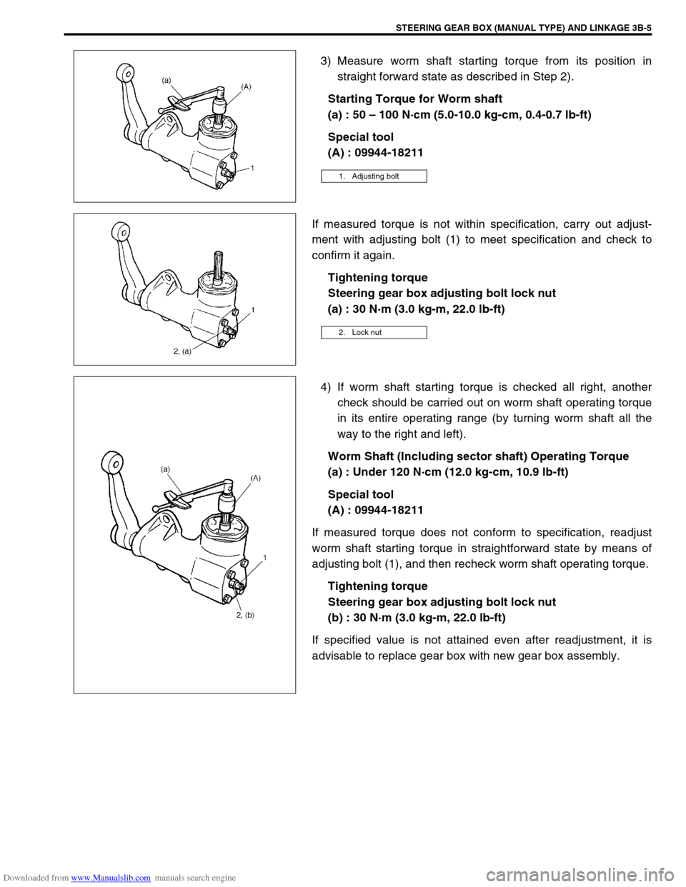
3) Measure worm shaft starting torque from its position in
straight forward state as described in Step 2).
Starting Torque for Worm shaft
(a) : 50 – 100 N·cm (5.0-10.0 kg-cm, 0.4-0.7 lb-ft)
Special tool
(A) : 09944-18211
If measured torque is not within specification, carry out adjust-
ment with adjusting bolt (1) to meet specification and check to
confirm it again.
Tightening torque
Steering gear box adjusting bolt lock nut
(a) : 30 N·m (3.0 kg-m, 22.0 lb-ft)
4) If worm shaft starting torque is checked all right, another
check should be carried out on worm shaft operating torque
in its entire operating range (by turning worm shaft all the
way to the right and left).
Worm Shaft (Including sector shaft) Operating Torque
(a) : Under 120 N·cm (12.0 kg-cm, 10.9 lb-ft)
Special tool
(A) : 09944-18211
If measured torque does not conform to specification, readjust
worm shaft starting torque in straightforward state by means of
adjusting bolt (1), and then recheck worm shaft operating torque.
Tightening torque
Steering gear box adjusting bolt lock nut
(b) : 30 N·m (3.0 kg-m, 22.0 lb-ft)
If specified value is not attained even after readjustment, it is
advisable to replace gear box with new gear box assembly.
1. Adjusting bolt
2. Lock nut
Page 129 of 687

Downloaded from www.Manualslib.com manuals search engine 3B-8 STEERING GEAR BOX (MANUAL TYPE) AND LINKAGE
Tie Rod And Drag Rod
REMOVAL
1) Hoist vehicle and remove wheel (s).
2) Remove tie rod end nut from steering knuckle.
3) Mark (3) one end of tie rod before removing the rod as
shown in figure to distinguish the correct installing direction
easy.
4) Disconnect tie rod end (2) from knuckle (1), using special
tool.
Special tool
(A) : 09913-65210
5) For ease of adjustment after installation, make marking (3) of
tie rod end lock nut position on tie rod thread. Then loosen
lock nut (2) and remove tie rod end (1) from tie rod.
INSTALLATION
1) Install tie rod end lock nut (2) and tie rod end (1) to tie rod
and/or drag rod. Align lock nut with mark (3) on tie rod
thread.
Page 130 of 687

Downloaded from www.Manualslib.com manuals search engine STEERING GEAR BOX (MANUAL TYPE) AND LINKAGE 3B-9
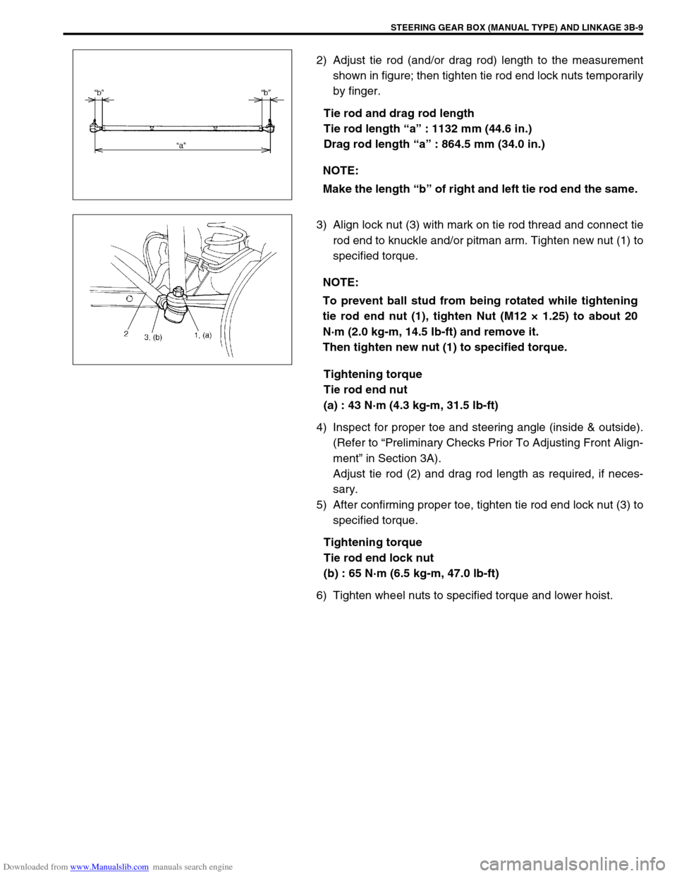
2) Adjust tie rod (and/or drag rod) length to the measurement
shown in figure; then tighten tie rod end lock nuts temporarily
by finger.
Tie rod and drag rod length
Tie rod length “a” : 1132 mm (44.6 in.)
Drag rod length “a” : 864.5 mm (34.0 in.)
3) Align lock nut (3) with mark on tie rod thread and connect tie
rod end to knuckle and/or pitman arm. Tighten new nut (1) to
specified torque.
Tightening torque
Tie rod end nut
(a) : 43 N·m (4.3 kg-m, 31.5 lb-ft)
4) Inspect for proper toe and steering angle (inside & outside).
(Refer to “Preliminary Checks Prior To Adjusting Front Align-
ment” in Section 3A).
Adjust tie rod (2) and drag rod length as required, if neces-
sary.
5) After confirming proper toe, tighten tie rod end lock nut (3) to
specified torque.
Tightening torque
Tie rod end lock nut
(b) : 65 N·m (6.5 kg-m, 47.0 lb-ft)
6) Tighten wheel nuts to specified torque and lower hoist.NOTE:
Make the length “b” of right and left tie rod end the same.
NOTE:
To prevent ball stud from being rotated while tightening
tie rod end nut (1), tighten Nut (M12 × 1.25) to about 20
N·m (2.0 kg-m, 14.5 Ib-ft) and remove it.
Then tighten new nut (1) to specified torque.
Page 131 of 687

Downloaded from www.Manualslib.com manuals search engine 3B-10 STEERING GEAR BOX (MANUAL TYPE) AND LINKAGE
Tightening Torque Specifications
Required Service Material
Special Tools
Fastening partTightening torque
Nm kg-m lb-ft
Steering gear box oil plug 4 0.4 3.0
Steering gear box adjusting bolt lock nut 30 3.0 22.0
Pitman arm mounting nut 135 13.5 98.0
Steering shaft joint bolt 25 2.5 18.0
Steering gear box nuts and bolt 80 8.0 58.0
Tie rod end nut and drag rod end nut
(knuckle side)43 4.3 31.5
Wheel nut 95 9.5 69.0
Tie rod end lock nut 65 6.5 47.0
Drag rod end nut (pitman arm side) 50 5.0 36.5
MaterialRecommended SUZUKI product
(Part Number)Use
Sealant SUZUKI BOND NO. 1215
(99000-31110)Thread of oil breathing plug
09913-65210 09944-18211
Tie-rod end remover Pinion torque checking socket
Page 132 of 687

Downloaded from www.Manualslib.com manuals search engine POWER STEERING (P/S) SYSTEM (If equipped) 3B1-1
6F1
6F2
6G
6H
6K
3B1
7D
7E
7F
7E
7F
8A
8B
8C
8D
8E
9
10
10A
10B
SECTION 3B1
POWER STEERING (P/S) SYSTEM
(If equipped)
CONTENTS
General Description ......................................3B1-2
Diagnosis .......................................................3B1-3
Diagnosis Table .......................................... 3B1-3
Steering Wheel Play Check ........................ 3B1-5
Steering Force Check ................................. 3B1-5
Power Steering Belt Check ......................... 3B1-6
Power Steering Belt Tension Adjustment .... 3B1-6
Power Steering Fluid Level Check .............. 3B1-6
Idle-Up System Check ................................ 3B1-7
Power Steering Fluid Leakage Check ......... 3B1-7Air Bleeding Procedure ............................... 3B1-8
Hydraulic Pressure In P/S Circuit Check .. 3B1-10
On-Vehicle Service ..................................... 3B1-12
Power Steering Belt .................................. 3B1-12
Power Steering (P/S) Pump ...................... 3B1-12
Power Steering (P/S) Gear Box ................ 3B1-18
Tightening Torque Specifications ............. 3B1-21
Required Service Materials ........................ 3B1-21
Special Tools ............................................... 3B1-21 WARNING:
For vehicles equipped with Supplemental Restraint (Air Bag) System :
Service on and around the air bag system components or wiring must be performed only by an
authorized SUZUKI dealer. Refer to “Air Bag System Components and Wiring Location View” under
“General Description” in air bag system section in order to confirm whether you are performing ser-
vice on or near the air bag system components or wiring. Please observe all WARNINGS and “Ser-
vice Precautions” under “On-Vehicle Service” in air bag system section before performing service
on or around the air bag system components or wiring. Failure to follow WARNINGS could result in
unintentional activation of the system or could render the system inoperative. Either of these two
conditions may result in severe injury.
Technical service work must be started at least 90 seconds after the ignition switch is turned to the
“LOCK” position and negative cable is disconnected from the battery. Otherwise, the system may
be activated by reserve energy in the Sensing and Diagnostic Module (SDM).
NOTE:
All steering gear fasteners are important attaching parts in that they could affect the performance of
vital parts and systems, and/or could result in major repair expense. They must be replaced with one
of the same part number or with an equivalent part if replacement becomes necessary. Do not use a
replacement part of lesser quality or substitute design. Torque values must be used as specified dur-
ing reassembly to assure proper retention of these parts.