Page 257 of 687

Downloaded from www.Manualslib.com manuals search engine 4B-4 PROPELLER SHAFTS
INSTALLATION
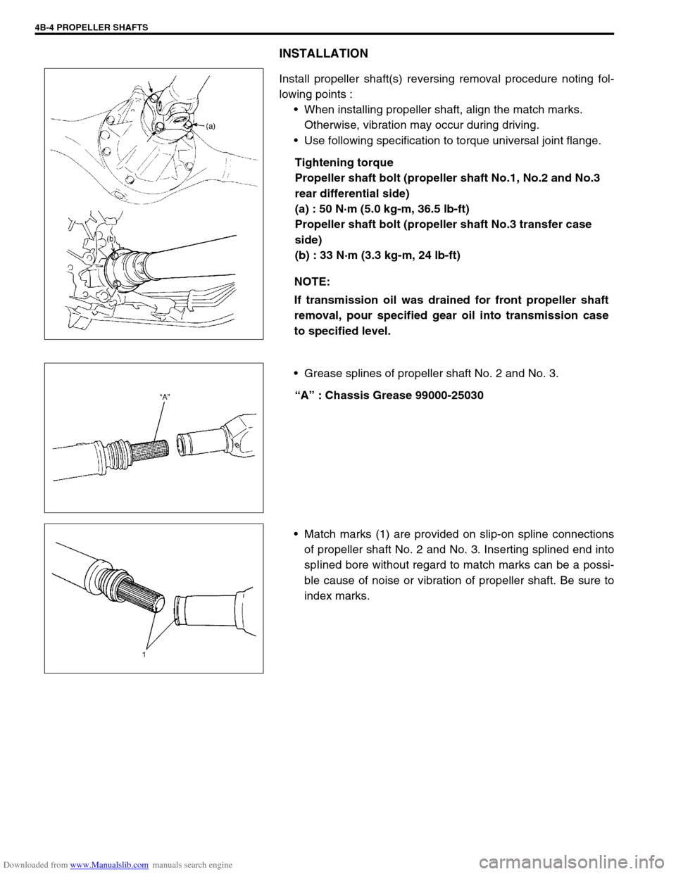
Install propeller shaft(s) reversing removal procedure noting fol-
lowing points :
When installing propeller shaft, align the match marks.
Otherwise, vibration may occur during driving.
Use following specification to torque universal joint flange.
Tightening torque
Propeller shaft bolt (propeller shaft No.1, No.2 and No.3
rear differential side)
(a) : 50 N·m (5.0 kg-m, 36.5 lb-ft)
Propeller shaft bolt (propeller shaft No.3 transfer case
side)
(b) : 33 N·m (3.3 kg-m, 24 lb-ft)
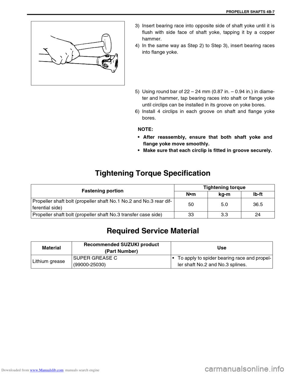
Grease splines of propeller shaft No. 2 and No. 3.
“A” : Chassis Grease 99000-25030
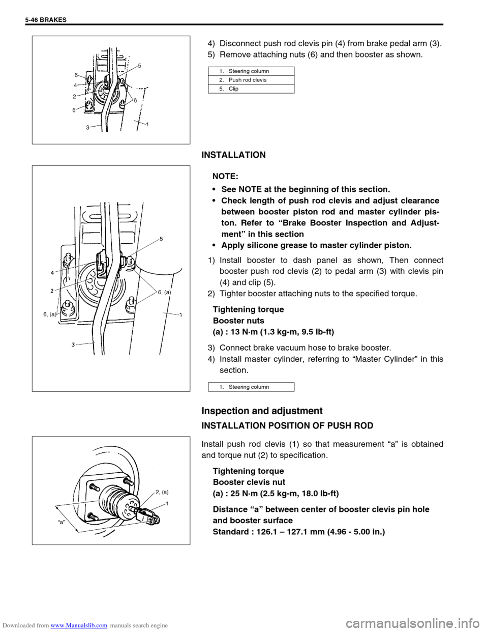
Match marks (1) are provided on slip-on spline connections
of propeller shaft No. 2 and No. 3. Inserting splined end into
spIined bore without regard to match marks can be a possi-
ble cause of noise or vibration of propeller shaft. Be sure to
index marks. NOTE:
If transmission oil was drained for front propeller shaft
removal, pour specified gear oil into transmission case
to specified level.
Page 259 of 687
Downloaded from www.Manualslib.com manuals search engine 4B-6 PROPELLER SHAFTS
6) Push out bearing race (2) on flange yoke (1) in the same
way as Step 2).
7) Holding bearing race (2) by a vise (3), tap flange yoke (1)
and take out race.
8) Take out bearing race (2) on the opposite side of flange yoke
(1) in the same way as Step 5) to Step 6).
REASSEMBLY
1) Apply grease to rollers (1) in bearing races (2).
“A” : Grease 99000-25030
2) With spider (4) inserted into bearing race (2) to prevent roll-
ers in race from coming out, insert bearing race (2) into shaft
yoke (3) until it is flush with side face of shaft yoke (3), tap-
ping it by a copper hammer (1).
CAUTION:
Do not reuse spider (1), bearings (2) and circlips. Other-
wise it may damage propeller shaft or cause abnormal
vibration or noise.
NOTE:
Make sure that rollers (1) in bearing race (2) are all in
place.
Page 260 of 687

Downloaded from www.Manualslib.com manuals search engine PROPELLER SHAFTS 4B-7
3) Insert bearing race into opposite side of shaft yoke until it is
flush with side face of shaft yoke, tapping it by a copper
hammer.
4) In the same way as Step 2) to Step 3), insert bearing races
into flange yoke.
5) Using round bar of 22 – 24 mm (0.87 in. – 0.94 in.) in diame-
ter and hammer, tap bearing races into shaft or flange yoke
until circlips can be installed in its groove on yoke bores.
6) Install 4 circlips in each groove on shaft and flange yoke
bores.
Tightening Torque Specification
Required Service Material
NOTE:
After reassembly, ensure that both shaft yoke and
flange yoke move smoothly.
Make sure that each circlip is fitted in groove securely.
Fastening portionTightening torque
Nm kg-m lb-ft
Propeller shaft bolt (propeller shaft No.1 No.2 and No.3 rear dif-
ferential side)50 5.0 36.5
Propeller shaft bolt (propeller shaft No.3 transfer case side) 33 3.3 24
MaterialRecommended SUZUKI product
(Part Number)Use
Lithium greaseSUPER GREASE C
(99000-25030)To apply to spider bearing race and propel-
ler shaft No.2 and No.3 splines.
Page 280 of 687
Downloaded from www.Manualslib.com manuals search engine BRAKES 5-19
PIPE
Inspect the tube for damage, cracks, dents and corrosion. If any
defect is found, replace it.
Front Disc Brake
1. Caliper pin bolt 10. Carrier bolt
2. Boot11. Brake caliper carrier
3. Cylinder slide bush
: Apply rubber grease to mating surface of caliper12. Pad clip
4. Bleeder plug cap 13. Disc brake caliper
5. Bleeder plug 14. Disc brake pad
6. Anti noise shim 15. Piston seal
: Apply brake fluid to all around part of piston seal
7. Disc brake piston
: Apply brake fluid to contact surface of cylinderTightening torque
8. Cylinder bootDo not reuse.
9. Seat ring (boot ring)
Page 284 of 687
Downloaded from www.Manualslib.com manuals search engine BRAKES 5-23
INSPECTION
Cylinder Slide Bush
Check slide bush for smooth movement as shown.
If it is found faulty, correct or replace. Apply rubber grease to bush
outer surface. Rubber grease should be the one whose viscosity
is less affected by such low temperature as – 40 °C (– 40 °F).
Bush Dust Boot and Cylinder Boot
Check boots for breakage, crack and damage. If defective,
replace.
Piston Seal
Excessive or uneven wear of pad lining may indicate unsmooth
return of the piston. In such a case, replace rubber seal.
1. Apply rubber grease
Page 285 of 687

Downloaded from www.Manualslib.com manuals search engine 5-24 BRAKES
ASSEMBLY
1) Check that slide bushes and boots for wear, corrosion, dam-
age, movement or deterioration. If it is found faulty, correct or
replace.
Apply rubber grease to bush outer surface. And then make
sure that each bush slides easily through each caliper bolt
hole.
2) Tighten bleeder plug to specified torque and install cap.
Tightening torque
Front caliper bleeder plug
(a) : 11 N·m (1.1 g-m, 8.0 lb-ft)
3) Piston seal is used to seal piston and cylinder and to adjust
clearance between pad and disc. Replace with a new one at
every overhaul. Fit piston seal into groove in cylinder taking
care not to twist it.
4) Before inserting piston (2) into cylinder, install new boot (1)
onto piston (2) as shown.
“A” : 2-grooved side directed inside
“B” : 3-grooved side directed outside CAUTION:
Wash each part cleanly before installation in the same
fluid as the one used in master cylinder reservoir.
Never use other fluid or thinner.
Before installing piston and piston seal to cylinder,
apply fluid to them.
After reassembling brake lines, bleed air from them.
NOTE:
Where temperature gets as low as – 30 °C (– 22 °F) in cold
weather, use rubber grease whose viscosity varies very
little even at – 40 °C (– 40 °F).
1. Apply rubber grease
Page 293 of 687
Downloaded from www.Manualslib.com manuals search engine 5-32 BRAKES
Brake shoe
REMOVAL
1) Remove brake drum referring to “Brake Drum” in this sec-
tion.
2) Remove shoe return spring lower (3), spring and rod assem-
bly (4) and shoe hold down springs (2) by turning shoe hold
down pins (1).
3) Remove parking brake shoe lever (5) from brake back plate.
INSPECT
Inspect lever for free movement against brake shoe web. If
defective, correct or replace.
Inspect ratchet or thread rod part for wear, sticking and cor-
rosion.
Inspect for damage or weakening.
Inspect each part with arrow for rust. If found defective,
replace.
INSTALLATION
Assemble parts as shown in reverse order of removal.
1) Apply rubber grease to brake back plate and parking brake
shoe lever as shown in the figure. WARNING:
Use special care when installing brake shoe return
spring. Failure in its proper installation may allow it to
spring back and cause personal injury.
1. Apply rubber grease
Page 307 of 687

Downloaded from www.Manualslib.com manuals search engine 5-46 BRAKES
4) Disconnect push rod clevis pin (4) from brake pedal arm (3).
5) Remove attaching nuts (6) and then booster as shown.
INSTALLATION
1) Install booster to dash panel as shown, Then connect
booster push rod clevis (2) to pedal arm (3) with clevis pin
(4) and clip (5).
2) Tighter booster attaching nuts to the specified torque.
Tightening torque
Booster nuts
(a) : 13 N·m (1.3 kg-m, 9.5 Ib-ft)
3) Connect brake vacuum hose to brake booster.
4) Install master cylinder, referring to “Master Cylinder” in this
section.
Inspection and adjustment
INSTALLATION POSITION OF PUSH ROD
Install push rod clevis (1) so that measurement “a” is obtained
and torque nut (2) to specification.
Tightening torque
Booster clevis nut
(a) : 25 N·m (2.5 kg-m, 18.0 Ib-ft)
Distance “a” between center of booster clevis pin hole
and booster surface
Standard : 126.1 – 127.1 mm (4.96 - 5.00 in.)
1. Steering column
2. Push rod clevis
5. Clip
NOTE:
See NOTE at the beginning of this section.
Check length of push rod clevis and adjust clearance
between booster piston rod and master cylinder pis-
ton. Refer to “Brake Booster Inspection and Adjust-
ment” in this section
Apply silicone grease to master cylinder piston.
1. Steering column