Page 131 of 687
Downloaded from www.Manualslib.com manuals search engine 3B-10 STEERING GEAR BOX (MANUAL TYPE) AND LINKAGE
Tightening Torque Specifications
Required Service Material
Special Tools
Fastening partTightening torque
Nm kg-m lb-ft
Steering gear box oil plug 4 0.4 3.0
Steering gear box adjusting bolt lock nut 30 3.0 22.0
Pitman arm mounting nut 135 13.5 98.0
Steering shaft joint bolt 25 2.5 18.0
Steering gear box nuts and bolt 80 8.0 58.0
Tie rod end nut and drag rod end nut
(knuckle side)43 4.3 31.5
Wheel nut 95 9.5 69.0
Tie rod end lock nut 65 6.5 47.0
Drag rod end nut (pitman arm side) 50 5.0 36.5
MaterialRecommended SUZUKI product
(Part Number)Use
Sealant SUZUKI BOND NO. 1215
(99000-31110)Thread of oil breathing plug
09913-65210 09944-18211
Tie-rod end remover Pinion torque checking socket
Page 137 of 687

Downloaded from www.Manualslib.com manuals search engine 3B1-6 POWER STEERING (P/S) SYSTEM (If equipped)
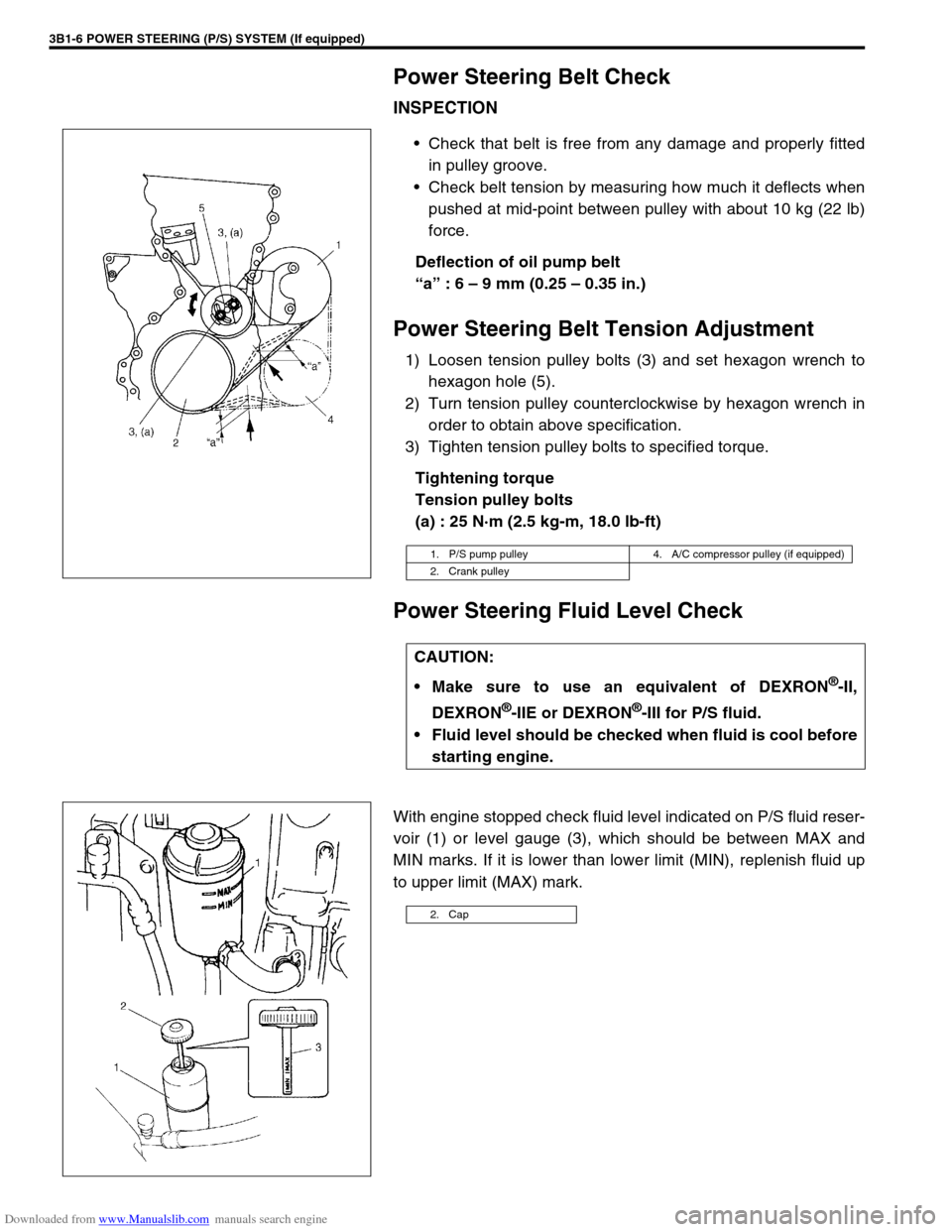
Power Steering Belt Check
INSPECTION
Check that belt is free from any damage and properly fitted
in pulley groove.
Check belt tension by measuring how much it deflects when
pushed at mid-point between pulley with about 10 kg (22 lb)
force.
Deflection of oil pump belt
“a” : 6 – 9 mm (0.25 – 0.35 in.)
Power Steering Belt Tension Adjustment
1) Loosen tension pulley bolts (3) and set hexagon wrench to
hexagon hole (5).
2) Turn tension pulley counterclockwise by hexagon wrench in
order to obtain above specification.
3) Tighten tension pulley bolts to specified torque.
Tightening torque
Tension pulley bolts
(a) : 25 N·m (2.5 kg-m, 18.0 lb-ft)
Power Steering Fluid Level Check
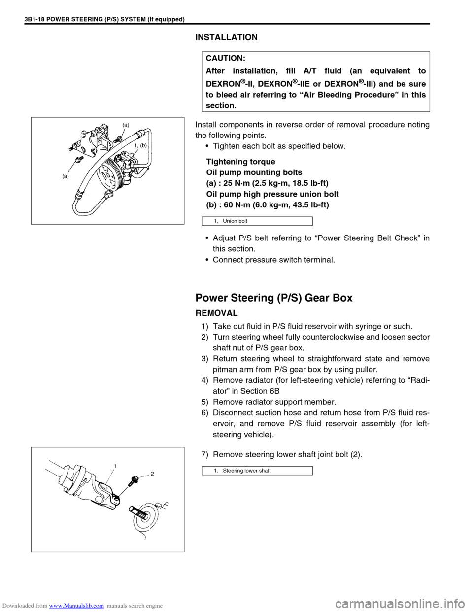
With engine stopped check fluid level indicated on P/S fluid reser-
voir (1) or level gauge (3), which should be between MAX and
MIN marks. If it is lower than lower limit (MIN), replenish fluid up
to upper limit (MAX) mark.
1. P/S pump pulley 4. A/C compressor pulley (if equipped)
2. Crank pulley
CAUTION:
Make sure to use an equivalent of DEXRON
®-II,
DEXRON
®-IIE or DEXRON®-III for P/S fluid.
Fluid level should be checked when fluid is cool before
starting engine.
2. Cap
Page 141 of 687

Downloaded from www.Manualslib.com manuals search engine 3B1-10 POWER STEERING (P/S) SYSTEM (If equipped)
Hydraulic Pressure In P/S Circuit Check
1) Clean where pipe is connected thoroughly, then disconnect
high pressure hose from high pressure pipe connector and
connect oil pressure gauge (special tool) as shown.
Special tool
(A) : 09915-77410
(B) : 09915-77420
2) Bleed air.
3) With engine running at idling speed, keep turning steering
wheel to the right and left till fluid in P/S fluid reservoir is
warmed to 50 to 60 °C (122 – 140 °F)
4) Back pressure check
With engine running at idling speed and hands off from
steering wheel, check hydraulic pressure.
If back pressure exceeds 980 kPa (10 kg/cm
2, 142 psi),
check control valve and pipes for obstruction.
Back pressure : 980 kPa (10 kg/cm
2, 142 psi)
1. To gear box 4. Union bolt
2. Attachment 5. Pressure hose
3. Washer
1. P/S fluid reservoir 5. Low pressure side
2. P/S pump 6. High pressure side
3. Steering gear box 7. Valve (open)
4. Oil pump pressure gauge
Page 142 of 687

Downloaded from www.Manualslib.com manuals search engine POWER STEERING (P/S) SYSTEM (If equipped) 3B1-11
5) Relief pressure check
a) Increase engine speed to about 1,500 to 1,600 rpm.
Close valve (6) gradually while watching pressure increase
indicated on gauge (4) and take reading of relief pressure
(maximum hydraulic pressure).
If higher than 8,400 kPa (85 kg/cm
2, 1208 psi), malfunction
of relief valve.
If lower than 6,400 kPa (65 kg/cm
2, 925 psi), failure of P/S
pump or settling of relief valve spring.
Relief pressure
6,400 – 8,400 kPa (65 – 85 kg/cm
2, 925 – 1208 psi)
b) Next, open gauge valve (6) fully and increase engine speed
to about 1,500 to 1,600 r/min. Then turn steering wheel to
the left or right fully and take reading of relief pressure.
If lower than 6,400 kPa (65 kg/cm
2, 1280 psi), failure in
steering gear.
Relief pressure
6,400 – 8,400 kPa (65 – 85 kg/cm
2, 925 – 1208 psi) CAUTION:
Be sure not to keep gauge valve closed for longer than
10 seconds.
Never keep steering wheel turned fully for longer than
10 seconds.
1. P/S fluid reservoir 3. Steering gear box
2. P/S pump 5. High pressure side
1. P/S fluid reservoir 4. Oil pressure gauge
2. P/S pump 5. High pressure side
3. Steering gear box
Page 144 of 687

Downloaded from www.Manualslib.com manuals search engine POWER STEERING (P/S) SYSTEM (If equipped) 3B1-13
5) Remove P/S pump (1) removing 3 mounting bolts (3).
DISASSEMBLY
1) Clean its exterior thoroughly.
2) With aluminum plates placed on vise first, grip pump case
with it.
3) Remove suction connector (10) and O-ring from pump body
(1).
4) Remove power steering pressure switch (3) from pump body
(1).
5) Remove relief valve (flow control valve) (2) and spring from
pump body (1).
6) Remove pump cover (11), O-ring and cam ring (6) from
pump body (1).
7) Remove vanes (9) from rotor (5).
8) Remove snap ring (8) from pump shaft (4) and pull out rotor
(5) and pulley (shaft) (4).
9) Remove side plate (7) and O-ring from pump body (1).
10) Remove oil seal from pump body (1).
INSPECTION
Pump body, cover and shaft
Check sliding surfaces of each part for wear and damage.
If any defect is found, replace pump assembly.CAUTION:
Clean couplers at intake and discharge ports com-
pletely before disconnection.
Plug ports of removed pump to prevent dust and any
foreign object from entering.
2. P/S pump bracket
1. Pulley 3. Pump cover
2. Pump body
Page 146 of 687

Downloaded from www.Manualslib.com manuals search engine POWER STEERING (P/S) SYSTEM (If equipped) 3B1-15
Check free length of relief valve spring (1).
Replace pump assembly if any defective is found.
Relief valve spring free length
Standard : 36.5 mm (1.44 in.)
Limit : 33.5 mm (1.32 in.)
ASSEMBLY
Reverse disassembly procedure for assembly, noting the follow-
ing.
1) Apply power steering fluid to shaft (2) outer surface and
grease to oil seal lip (1) and insert it from oil seal side.
“A” : Grease 99000-25010
2) Apply power steering fluid to O-rings and fit them to pump
body.
3) Install side plate (2) to pump body.
4) Apply power steering fluid to sliding surface of rotor (1).
5) Install rotor (1) to shaft, directing “dot” (2) marked side of
rotor toward pump cover (facing up).
6) Install new snap ring to shaft, then make sure to fit snap ring
into shaft groove securely.
NOTE:
Carefully align the dowel pins (3) on the side plate (2) at
bolt hole (1) as shown in figure.
NOTE:
Never reuse the removed snap ring.
Page 147 of 687
Downloaded from www.Manualslib.com manuals search engine 3B1-16 POWER STEERING (P/S) SYSTEM (If equipped)
7) Apply power steering fluid to sliding surface of cam ring (1).
8) Install cam ring (1) to pump body. The tapered end of cam
ring (1) should face the side plate (2).
9) Apply power steering fluid to each vane (2).
10) Install vanes (10 pipes) (2) to rotor (1).
11) Apply power steering fluid to O-ring (1) and fit it to pump
body.
12) Install O-ring (1) to pump body.
13) Apply power steering fluid to sliding surface of pump cover
(1) and rotor.
14) Match the dowel pins (2) to the holes of the cover plate as
shown and install pump cover to pump body.
15) Tighten pump cover bolts to specified torque.
Tightening torque
Oil pump cover bolts
(a) : 28 N·m (2.8 kg-m, 20.0 lb-ft)
NOTE:
After installing pump cover (1), check to make sure that
shaft can be turned by hand.
Page 149 of 687

Downloaded from www.Manualslib.com manuals search engine 3B1-18 POWER STEERING (P/S) SYSTEM (If equipped)
INSTALLATION
Install components in reverse order of removal procedure noting
the following points.
Tighten each bolt as specified below.
Tightening torque
Oil pump mounting bolts
(a) : 25 N·m (2.5 kg-m, 18.5 lb-ft)
Oil pump high pressure union bolt
(b) : 60 N·m (6.0 kg-m, 43.5 lb-ft)
Adjust P/S belt referring to “Power Steering Belt Check” in
this section.
Connect pressure switch terminal.
Power Steering (P/S) Gear Box
REMOVAL
1) Take out fluid in P/S fluid reservoir with syringe or such.
2) Turn steering wheel fully counterclockwise and loosen sector
shaft nut of P/S gear box.
3) Return steering wheel to straightforward state and remove
pitman arm from P/S gear box by using puller.
4) Remove radiator (for left-steering vehicle) referring to “Radi-
ator” in Section 6B
5) Remove radiator support member.
6) Disconnect suction hose and return hose from P/S fluid res-
ervoir, and remove P/S fluid reservoir assembly (for left-
steering vehicle).
7) Remove steering lower shaft joint bolt (2).CAUTION:
After installation, fill A/T fluid (an equivalent to
DEXRON
®-II, DEXRON®-IIE or DEXRON®-III) and be sure
to bleed air referring to “Air Bleeding Procedure” in this
section.
1. Union bolt
1. Steering lower shaft