Page 286 of 687
Downloaded from www.Manualslib.com manuals search engine BRAKES 5-25
5) Fit boot as it is in figure into boot groove in cylinder with fin-
gers.
6) Insert piston into cylinder by hand and fit boot in boot groove
in piston.
7) To confirm that boot is fitted in its groove in cylinder properly,
pull piston out of cylinder a little but do not take it all out.
8) Insert piston into cylinder by hand.
9) Install piston set ring.
INSTALLATION
1) Install caliper to caliper carrier.
2) Torque caliper pin bolts (1) to specification.
Tightening torque
Brake caliper pin bolts
(a) : 22 N·m (2.2 kg-m, 16.0 lb-ft)
NOTE:
Boot’s face “B” should be at the same level from cylin-
der’s face “A” all around.
NOTE:
Make sure that boots are fit into groove securely.
Page 289 of 687
Downloaded from www.Manualslib.com manuals search engine 5-28 BRAKES
CHECK FOR FRONT BRAKE AFTER INSTALLATION
Mount tires and make certain that they rotate smoothly, with a
force of less than 3.0 kg (6.6 Ib).
If tire rotation is heavy, check the following:
Piston, piston seal and cylinder slide bush of caliper for
installation.
Wheel bearings for breakage.
Disc for flatness (Improper flatness brings disc into contact
with lining during rotation and makes rotation heavy).
To check this, measure disc deflection.NOTE:
For above check the following must be observed.
Jack up front wheels, both right and left, off the
ground.
Shift transfer shift lever to 2H (rear wheel) position (if
equipped) and start engine for a few seconds then
stop.
Side figure shows outer periphery of tire.
Be careful not to depress brake pedal when checking
tire for rotation.
1. String
2. Spring measure
Page 290 of 687
Downloaded from www.Manualslib.com manuals search engine BRAKES 5-29
Rear Brake
Brake drum
REMOVAL
1) Hoist vehicle and pull up parking brake lever.
2) Remove wheel.
3) Release parking brake lever.
4) Loosen parking brake cable adjusting nut (1).
1. Brake back plate 5. Shoe return spring lower 9. Shoe hold down pin
2. Brake shoe 6. Adjuster lever 10. Wheel cylinder
: Apply brake fluid to piston cap
3. Spring and rod assembly 7. Adjuster spring Tightening torque
4. Parking brake shoe lever 8. Shoe hold down spring
Page 291 of 687

Downloaded from www.Manualslib.com manuals search engine 5-30 BRAKES
5) To increase clearance between brake shoe and brake drum,
remove rubber plug from brake back plate and turn adjuster
downward with flat-head screw driver.
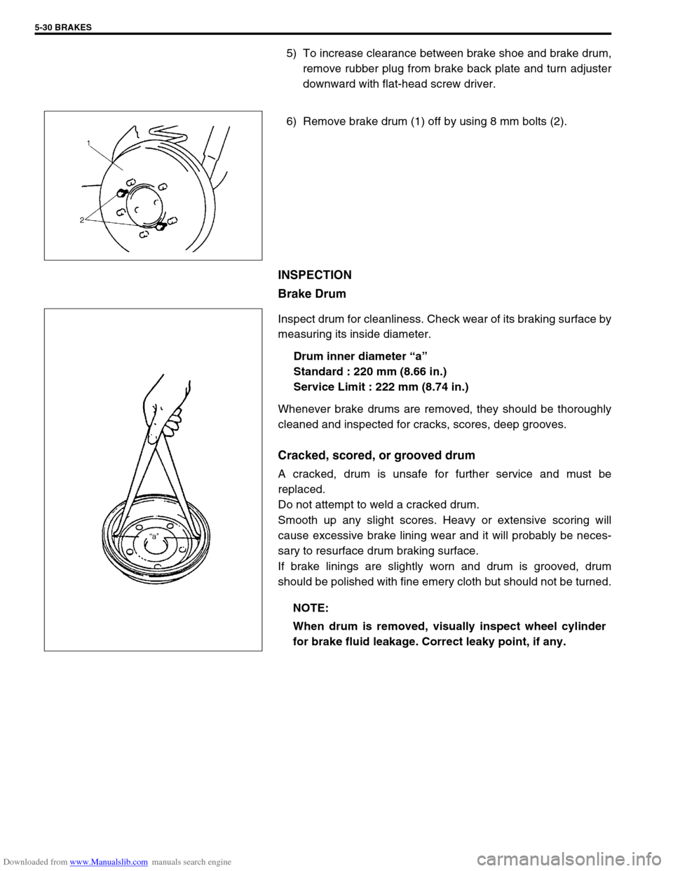
6) Remove brake drum (1) off by using 8 mm bolts (2).
INSPECTION
Brake Drum
Inspect drum for cleanliness. Check wear of its braking surface by
measuring its inside diameter.
Drum inner diameter “a”
Standard : 220 mm (8.66 in.)
Service Limit : 222 mm (8.74 in.)
Whenever brake drums are removed, they should be thoroughly
cleaned and inspected for cracks, scores, deep grooves.
Cracked, scored, or grooved drum
A cracked, drum is unsafe for further service and must be
replaced.
Do not attempt to weld a cracked drum.
Smooth up any slight scores. Heavy or extensive scoring will
cause excessive brake lining wear and it will probably be neces-
sary to resurface drum braking surface.
If brake linings are slightly worn and drum is grooved, drum
should be polished with fine emery cloth but should not be turned.
NOTE:
When drum is removed, visually inspect wheel cylinder
for brake fluid leakage. Correct leaky point, if any.
Page 294 of 687
Downloaded from www.Manualslib.com manuals search engine BRAKES 5-33
2) Install shoe hold down springs (2) by pushing them down in
place and turning hold down pins (1).
3) Install shoe return spring and parking brake shoe lever
spring.
4) For procedure hereafter, refer to “Brake Drum” in this sec-
tion.
Wheel Cylinder
REMOVAL
1) Remove brake drum referring to “Brake Drum” in this sec-
tion.
2) Remove brake shoe referring to “Brake Shoe” in this section.
3) Loosen brake pipe flare nut (or nuts) but only within the
extent that fluid does not leak.
4) Remove wheel cylinder mounting bolts. Disconnect brake
pipe (or pipes) from wheel cylinder and put wheel cylinder
breather plug cap (1) onto pipe to prevent fluid from spilling.
INSPECTION
Inspect wheel cylinder disassembled parts for wear, cracks, cor-
rosion or damage.
3. Shoe return spring lower
4. Spring and rod assembly
5. Adjuster lever
6. Adjuster spring
NOTE:
Clean wheel cylinder components with brake fluid.
Page 295 of 687

Downloaded from www.Manualslib.com manuals search engine 5-34 BRAKES
INSTALLATION
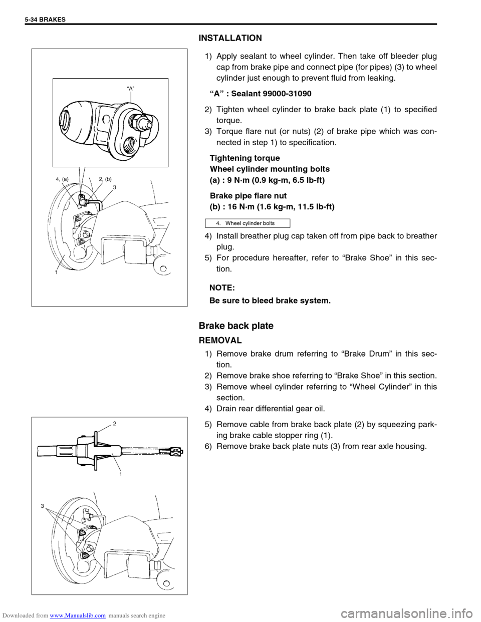
1) Apply sealant to wheel cylinder. Then take off bleeder plug
cap from brake pipe and connect pipe (for pipes) (3) to wheel
cylinder just enough to prevent fluid from leaking.
“A” : Sealant 99000-31090
2) Tighten wheel cylinder to brake back plate (1) to specified
torque.
3) Torque flare nut (or nuts) (2) of brake pipe which was con-
nected in step 1) to specification.
Tightening torque
Wheel cylinder mounting bolts
(a) : 9 N·m (0.9 kg-m, 6.5 lb-ft)
Brake pipe flare nut
(b) : 16 N·m (1.6 kg-m, 11.5 lb-ft)
4) Install breather plug cap taken off from pipe back to breather
plug.
5) For procedure hereafter, refer to “Brake Shoe” in this sec-
tion.
Brake back plate
REMOVAL
1) Remove brake drum referring to “Brake Drum” in this sec-
tion.
2) Remove brake shoe referring to “Brake Shoe” in this section.
3) Remove wheel cylinder referring to “Wheel Cylinder” in this
section.
4) Drain rear differential gear oil.
5) Remove cable from brake back plate (2) by squeezing park-
ing brake cable stopper ring (1).
6) Remove brake back plate nuts (3) from rear axle housing.
4. Wheel cylinder bolts
NOTE:
Be sure to bleed brake system.
Page 296 of 687
Downloaded from www.Manualslib.com manuals search engine BRAKES 5-35
7) Using special tools, draw out rear axle shaft with brake back
plate.
Special tool
(A) : 09943-35511
(B) : 09942-15510
8) Remove wheel bearing retainer and wheel sensor ring (if
equipped with ABS), refer to “Rear Axle Shaft and Wheel
Bearing” in Section 3E.
9) Remove brake back plate from axle shaft.
INSTALLATION
1) Install wheel cylinder, and tighten wheel cylinder bolts to
specified torque. Refer to “Wheel Cylinder” in this section.
2) Install brake back plate (2) to axle shaft (1).
3) For installation procedure here after perform “Rear Axle
Shaft and Wheel Bearing” in Section 3E.
3. Wheel bearing
4. Retainer ring
Page 297 of 687
Downloaded from www.Manualslib.com manuals search engine 5-36 BRAKES
Master Cylinder
Master Cylinder Reservoir
REMOVAL
1) Disconnect reservoir lead wire at coupler.
2) Clean outside of reservoir (1).
3) Take out fluid with syringe or such.
4) Remove reservoir connector pin (2) by using special tool.
Special tool
(A) : 09922-85811
Remove reservoir (1).
CAUTION:
Brake fluid is extremely damaging to paint.
Do not allow brake fluid to get on painted surfaces.
2. Connector pin
3. Grommets