Page 498 of 687
Downloaded from www.Manualslib.com manuals search engine ENGINE MECHANICAL (M13 ENGINE) 6A1-17
3) Install cylinder head cover to cylinder head.
4) Tighten bolts in such order as indicated in figure a little at a
time till they are tightened to specified torque.
Tightening torque
Cylinder head cover bolts (a) : 8 N·m (0.8 kg-m, 6.0 lb-ft)
5) Connect breather hose (1) and PCV hose (2).
6) Install oil level gauge (3).
7) Install ignition coil assemblies with high-tension cord.
8) Connect ignition coil couplers.
9) Install cylinder head upper cover.
10) Connect accelerator cable to clamp (For left hand steering
vehicle only).
11) Connect negative cable at battery.NOTE:
When installing cylinder head cover, use care so that cyl-
inder head cover gasket or spark plug hole gaskets will
not get out of place or fall off.
Page 505 of 687
Downloaded from www.Manualslib.com manuals search engine 6A1-24 ENGINE MECHANICAL (M13 ENGINE)
Oil Pan and Oil Pump Strainer
REMOVAL
1) Remove oil level gauge.
2) Remove air cleaner outlet No.1 (1) and No.2 (2) hoses and
breather hose (3).
3) To facilitate and ensure removal of oil pan, increase clear-
ance between engine and vehicle body according to the fol-
lowing procedure.
a) Install support device (1).
b) Loosen engine mounting bracket bolts (2), but do not
remove them.
c) Hoist engine 10 – 15 mm (0.4 – 0.6 in.).
[A] : Sealant application amount 3. O-ring 8. Oil pan nut
“a” : 3 mm (0.12 in.) 4. Gasket 9. Oil pan bolt
“b” : 2 mm (0.08 in.) 5. Drain plug Tightening torque
1. Oil pan
: Apply sealant 99000-31150 to mating surface.6. Strainer bolt Do not reuse.
2. Strainer 7. Bracket bolt
CAUTION:
Do not hoist engine more than instructed above. That
may cause trouble to engine or transmission.
Page 508 of 687
Downloaded from www.Manualslib.com manuals search engine ENGINE MECHANICAL (M13 ENGINE) 6A1-27
6) Lower engine and tighten engine mounting bracket bolts to
specified torque.
Tightening torque
Engine mounting bracket bolts
(a) : 50 N·m (5.0 kg-m, 36.5 lb-ft)
7) Install oil level gauge.
8) Refill engine with engine oil referring to “Engine Oil and Filter
Change” in Section 0B.
9) Verify that there is no engine oil leakage at each connection.
Page 580 of 687

Downloaded from www.Manualslib.com manuals search engine ENGINE COOLING 6B-3
Radiator Cap
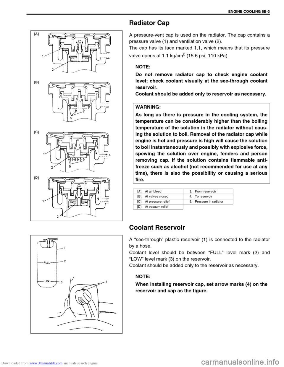
A pressure-vent cap is used on the radiator. The cap contains a
pressure valve (1) and ventilation valve (2).
The cap has its face marked 1.1, which means that its pressure
valve opens at 1.1 kg/cm
2 (15.6 psi, 110 kPa).
Coolant Reservoir
A “see-through” plastic reservoir (1) is connected to the radiator
by a hose.
Coolant level should be between “FULL” level mark (2) and
“LOW” level mark (3) on the reservoir.
Coolant should be added only to the reservoir as necessary.NOTE:
Do not remove radiator cap to check engine coolant
level; check coolant visually at the see-through coolant
reservoir.
Coolant should be added only to reservoir as necessary.
WARNING:
As long as there is pressure in the cooling system, the
temperature can be considerably higher than the boiling
temperature of the solution in the radiator without caus-
ing the solution to boil. Removal of the radiator cap while
engine is hot and pressure is high will cause the solution
to boil instantaneously and possibly with explosive force,
spewing the solution over engine, fenders and person
removing cap. If the solution contains flammable anti-
freeze such as alcohol (not recommended for use at any
time), there is also the possibility or causing a serious
fire.
[A]: At air bleed 3. From reservoir
[B]: At valves closed 4. To reservoir
[C]: At pressure relief 5. Pressure in radiator
[D]: At vacuum relief
NOTE:
When installing reservoir cap, set arrow marks (4) on the
reservoir and cap as the figure.
Page 584 of 687

Downloaded from www.Manualslib.com manuals search engine ENGINE COOLING 6B-7
Coolant Level
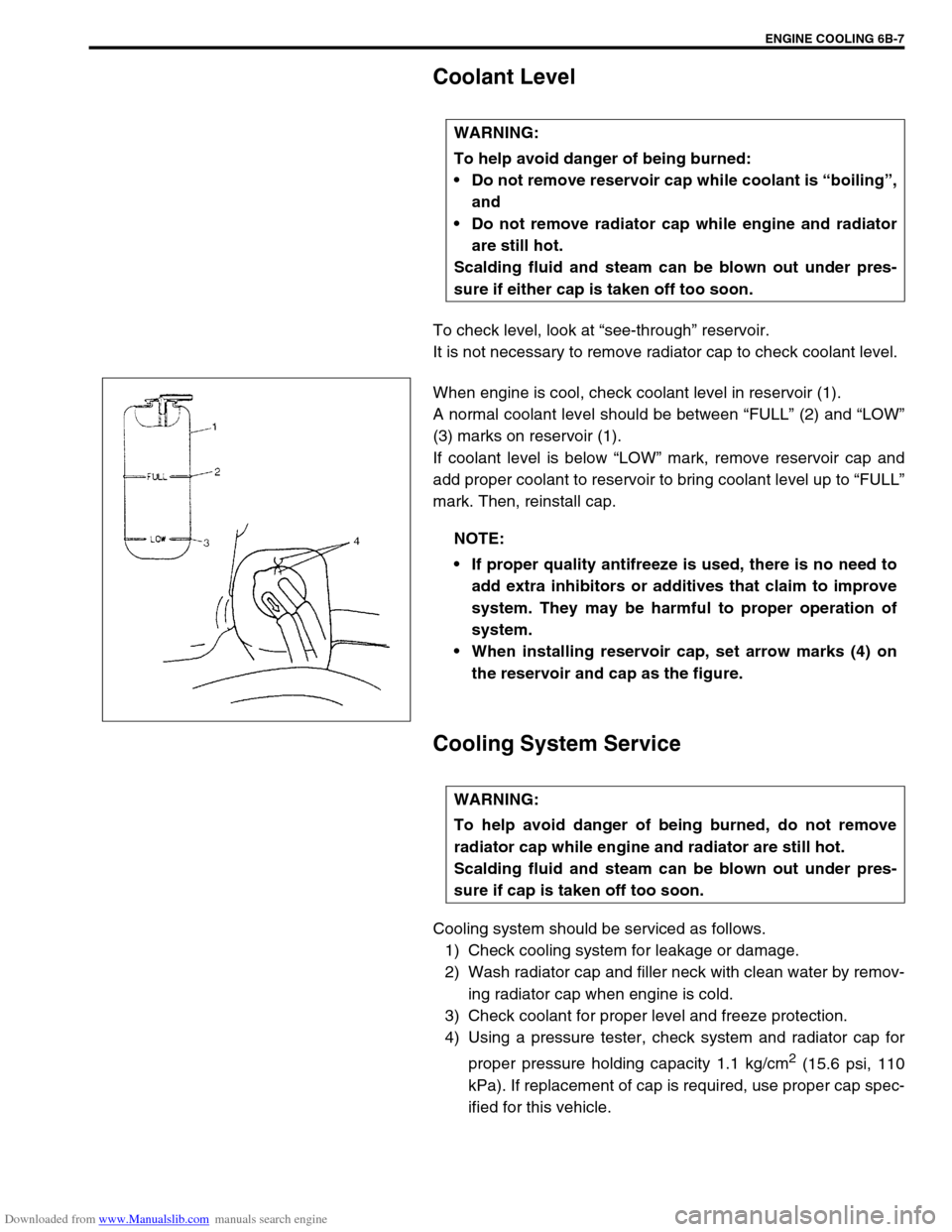
To check level, look at “see-through” reservoir.
It is not necessary to remove radiator cap to check coolant level.
When engine is cool, check coolant level in reservoir (1).
A normal coolant level should be between “FULL” (2) and “LOW”
(3) marks on reservoir (1).
If coolant level is below “LOW” mark, remove reservoir cap and
add proper coolant to reservoir to bring coolant level up to “FULL”
mark. Then, reinstall cap.
Cooling System Service
Cooling system should be serviced as follows.
1) Check cooling system for leakage or damage.
2) Wash radiator cap and filler neck with clean water by remov-
ing radiator cap when engine is cold.
3) Check coolant for proper level and freeze protection.
4) Using a pressure tester, check system and radiator cap for
proper pressure holding capacity 1.1 kg/cm
2 (15.6 psi, 110
kPa). If replacement of cap is required, use proper cap spec-
ified for this vehicle. WARNING:
To help avoid danger of being burned:
Do not remove reservoir cap while coolant is “boiling”,
and
Do not remove radiator cap while engine and radiator
are still hot.
Scalding fluid and steam can be blown out under pres-
sure if either cap is taken off too soon.
NOTE:
If proper quality antifreeze is used, there is no need to
add extra inhibitors or additives that claim to improve
system. They may be harmful to proper operation of
system.
When installing reservoir cap, set arrow marks (4) on
the reservoir and cap as the figure.
WARNING:
To help avoid danger of being burned, do not remove
radiator cap while engine and radiator are still hot.
Scalding fluid and steam can be blown out under pres-
sure if cap is taken off too soon.
Page 603 of 687
Downloaded from www.Manualslib.com manuals search engine 6C-8 ENGINE FUEL
INSPECTION
Check fuel pump assembly for damage.
Check fuel suction filter (1) for evidence of dirt and contamination.
If present, replace or clean and check for presence of dirt in fuel
tank.
For inspection of fuel pump itself, refer to “Table B – 3 Fuel Pres-
sure Check” in Section 6.
For inspection of fuel level gauge, refer to “Fuel Meter / Fuel
Gauge Unit” in Section 8.
DISASSEMBLY / REASSEMBLY
2. Fuel filter & bracket assembly
3. Fuel pump motor & level gauge assembly
“A” : Apply oil 4. Housing 8. Cushion
1. Bracket sub assembly (including fuel filter) 5. Lead wire 9. Bracket
2. Grommet 6. Fuel level gauge 10. Spacer
3. Tube 7. Fuel pump
Page 610 of 687

Downloaded from www.Manualslib.com manuals search engine ENGINE AND EMISSION CONTROL SYSTEM 6E-5
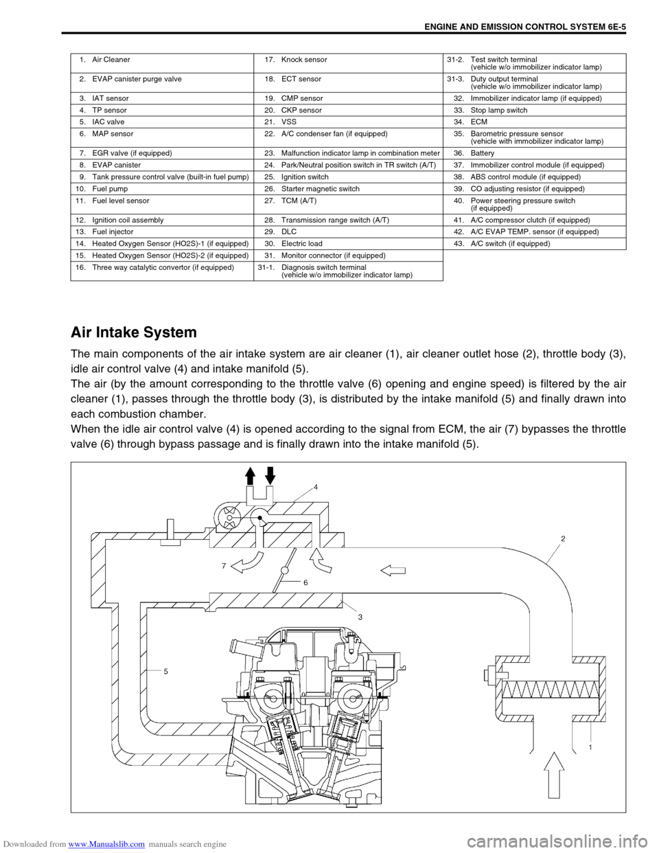
Air Intake System
The main components of the air intake system are air cleaner (1), air cleaner outlet hose (2), throttle body (3),
idle air control valve (4) and intake manifold (5).
The air (by the amount corresponding to the throttle valve (6) opening and engine speed) is filtered by the air
cleaner (1), passes through the throttle body (3), is distributed by the intake manifold (5) and finally drawn into
each combustion chamber.
When the idle air control valve (4) is opened according to the signal from ECM, the air (7) bypasses the throttle
valve (6) through bypass passage and is finally drawn into the intake manifold (5).
1. Air Cleaner 17. Knock sensor 31-2. Test switch terminal
(vehicle w/o immobilizer indicator lamp)
2. EVAP canister purge valve 18. ECT sensor 31-3. Duty output terminal
(vehicle w/o immobilizer indicator lamp)
3. IAT sensor 19. CMP sensor 32. Immobilizer indicator lamp (if equipped)
4. TP sensor 20. CKP sensor 33. Stop lamp switch
5. IAC valve 21. VSS 34. ECM
6. MAP sensor 22. A/C condenser fan (if equipped) 35. Barometric pressure sensor
(vehicle with immobilizer indicator lamp)
7. EGR valve (if equipped) 23. Malfunction indicator lamp in combination meter 36. Battery
8. EVAP canister 24. Park/Neutral position switch in TR switch (A/T) 37. Immobilizer control module (if equipped)
9. Tank pressure control valve (built-in fuel pump) 25. Ignition switch 38. ABS control module (if equipped)
10. Fuel pump 26. Starter magnetic switch 39. CO adjusting resistor (if equipped)
11. Fuel level sensor 27. TCM (A/T) 40. Power steering pressure switch
(if equipped)
12. Ignition coil assembly 28. Transmission range switch (A/T) 41. A/C compressor clutch (if equipped)
13. Fuel injector 29. DLC 42. A/C EVAP TEMP. sensor (if equipped)
14. Heated Oxygen Sensor (HO2S)-1 (if equipped) 30. Electric load 43. A/C switch (if equipped)
15. Heated Oxygen Sensor (HO2S)-2 (if equipped) 31. Monitor connector (if equipped)
16. Three way catalytic convertor (if equipped) 31-1. Diagnosis switch terminal
(vehicle w/o immobilizer indicator lamp)
Page 615 of 687

Downloaded from www.Manualslib.com manuals search engine 6E-10 ENGINE AND EMISSION CONTROL SYSTEM
1. CKP sensor 20. Power steering pressure switch
(if equipped)39. Ignition coil assembly (for No.1 and No.4 spark plugs)
2. CMP sensor 21. A/C switch 40. Ignition coil assembly (for No.2 and No.3 spark plugs)
3. VSS 22. A/C refrigerant pressure switch
(if equipped)41. Stop lamp switch
4. MAP sensor 23. Immobilizer control module (if equipped) 42. Stop lamp
5. Knock sensor 24. Data link connector 43. Lighting switch
6. TP sensor 25. Injector No.1 44. Position lamp
7. ECT sensor 26. Injector No.2 45. Rear defogger switch (if equipped)
8. IAT sensor 27. Injector No.3 46. Rear defogger (if equipped)
9. Heated oxygen sensor-1 (if equipped) 28. Injector No.4 47. A/C compressor clutch (if equipped)
10. Heated oxygen sensor-2 (if equipped) 29. IAC valve 48. Ignition switch
11. A/C evaporator temp. sensor (if equipped) 30. EVAP canister purge valve 49. Main relay
12. Speedometer 31. Fuel pump relay 50. CO adjusting register (if equipped)
13. Fuel level sensor 32. Fuel pump 51. Starting motor
14. TCM (A/T) 33. A/C condenser fan relay (if equipped) 52. 4WD controller (4WD)
15. Transmission range switch (A/T) 34. A/C condenser fan motor (if equipped) 53. ABS control module (if equipped)
16. Shift lock solenoid (A/T, if equipped) 35. EGR valve (if equipped) 54. Engine ground
17. Backup lamp 36. Malfunction indicator lamp 55. Body ground
18. Heater fan motor 37. Immobilizer indicator lamp (if equipped)
19. Heater fan switch 38. Monitor connector (vehicle without immo-
bilizer indicator lamp)