Page 137 of 687

Downloaded from www.Manualslib.com manuals search engine 3B1-6 POWER STEERING (P/S) SYSTEM (If equipped)
Power Steering Belt Check
INSPECTION
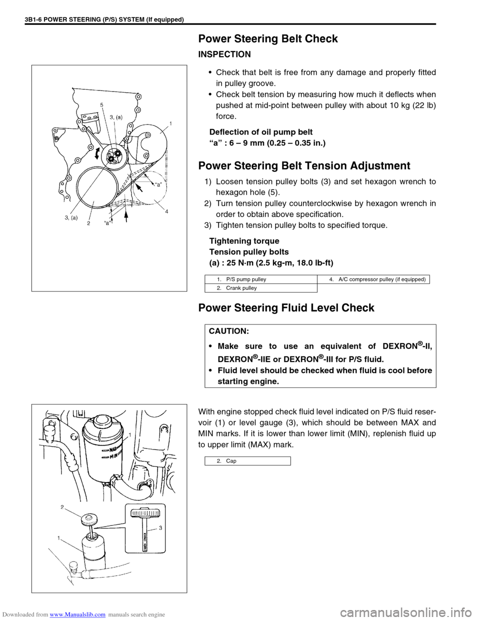
Check that belt is free from any damage and properly fitted
in pulley groove.
Check belt tension by measuring how much it deflects when
pushed at mid-point between pulley with about 10 kg (22 lb)
force.
Deflection of oil pump belt
“a” : 6 – 9 mm (0.25 – 0.35 in.)
Power Steering Belt Tension Adjustment
1) Loosen tension pulley bolts (3) and set hexagon wrench to
hexagon hole (5).
2) Turn tension pulley counterclockwise by hexagon wrench in
order to obtain above specification.
3) Tighten tension pulley bolts to specified torque.
Tightening torque
Tension pulley bolts
(a) : 25 N·m (2.5 kg-m, 18.0 lb-ft)
Power Steering Fluid Level Check
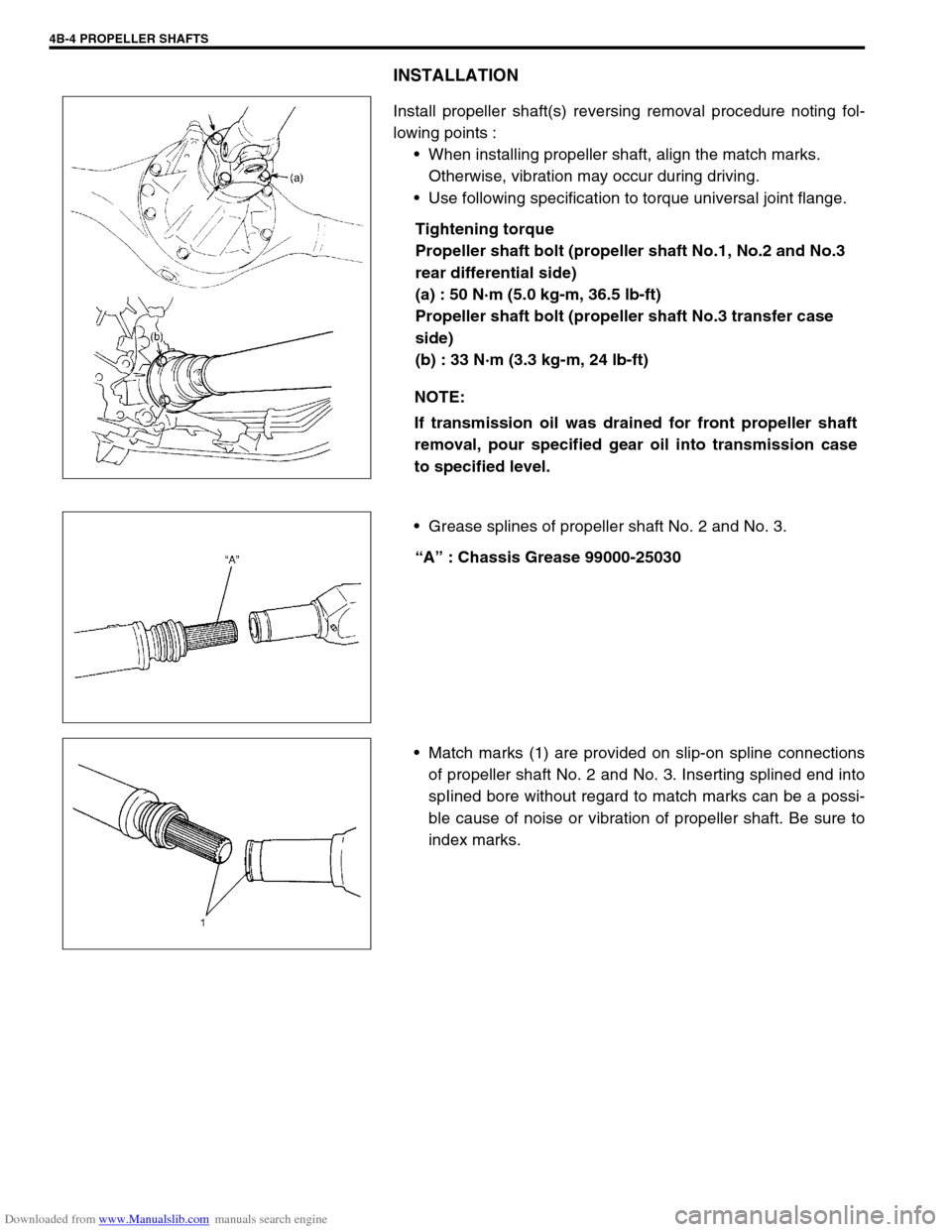
With engine stopped check fluid level indicated on P/S fluid reser-
voir (1) or level gauge (3), which should be between MAX and
MIN marks. If it is lower than lower limit (MIN), replenish fluid up
to upper limit (MAX) mark.
1. P/S pump pulley 4. A/C compressor pulley (if equipped)
2. Crank pulley
CAUTION:
Make sure to use an equivalent of DEXRON
®-II,
DEXRON
®-IIE or DEXRON®-III for P/S fluid.
Fluid level should be checked when fluid is cool before
starting engine.
2. Cap
Page 257 of 687

Downloaded from www.Manualslib.com manuals search engine 4B-4 PROPELLER SHAFTS
INSTALLATION
Install propeller shaft(s) reversing removal procedure noting fol-
lowing points :
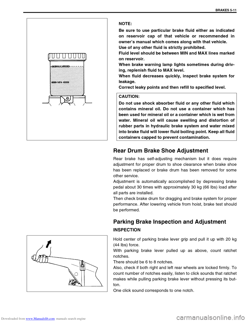
When installing propeller shaft, align the match marks.
Otherwise, vibration may occur during driving.
Use following specification to torque universal joint flange.
Tightening torque
Propeller shaft bolt (propeller shaft No.1, No.2 and No.3
rear differential side)
(a) : 50 N·m (5.0 kg-m, 36.5 lb-ft)
Propeller shaft bolt (propeller shaft No.3 transfer case
side)
(b) : 33 N·m (3.3 kg-m, 24 lb-ft)
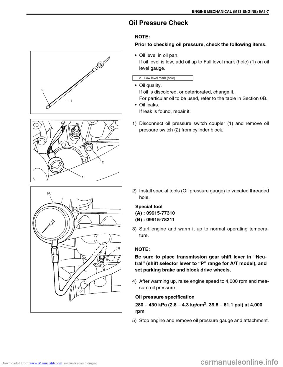
Grease splines of propeller shaft No. 2 and No. 3.
“A” : Chassis Grease 99000-25030
Match marks (1) are provided on slip-on spline connections
of propeller shaft No. 2 and No. 3. Inserting splined end into
spIined bore without regard to match marks can be a possi-
ble cause of noise or vibration of propeller shaft. Be sure to
index marks. NOTE:
If transmission oil was drained for front propeller shaft
removal, pour specified gear oil into transmission case
to specified level.
Page 265 of 687

Downloaded from www.Manualslib.com manuals search engine 5-4 BRAKES
Diagnosis
Road Testing Brakes
Brakes should be tested on dry, clean, smooth and reasonably level roadway which is not crowned. Road test
brakes by making brake applications with both light and heavy pedal forces at various speeds to determine if the
vehicle stops evenly and effectively.
Also drive vehicle to see if it leads to one side or the other without brake application. If it does, check the tire
pressure, front end alignment and front suspension attachments for looseness. See diagnosis table for other
causes.
Brake Fluid Leaks
Check the master cylinder fluid levels. While a slight drop in reservoir level does result from normal lining wear,
an abnormally low level indicates a leak in the system. In such a case, check the entire brake system for leak-
age. If even a slight evidence of leakage is noted, the cause should be corrected or defective parts should be
replaced.
If fluid level is lower than the minimum level of reservoir, refilling is necessary. Fill reservoir with specified brake
fluid.
Brake fluid: Refer to reservoir tank cap.
Substandard or Contaminated Brake Fluid
Improper brake fluid, mineral oil or water in the fluid may cause the brake fluid to boil or the rubber components
in the hydraulic system to deteriorate.
If primary piston cups are swollen, then rubber parts have deteriorated. This deterioration may also be evi-
denced by swollen wheel cylinder piston cups on the drum brake wheels.
If deterioration of rubber is evident, disassemble all hydraulic parts and wash with alcohol. Dry these parts with
compressed air before assembly to keep alcohol out of the system. Replace all rubber parts in the system,
including hoses. Also, when working on the brake mechanisms, check for fluid on the linings. If excessive fluid is
found, replace the linings.
If master cylinder piston seals are satisfactory, check for leakage or excessive heat conditions. If condition is not
found, drain fluid, flush with brake fluid, refill and bleed the system.
The system must be flushed if there is any doubt as to the grade of fluid in the system or if fluid has been used
which contained parts that have been subjected to contaminated fluid.CAUTION:
Since brake system of this vehicle is factory-filled with brake fluid indicated on reservoir tank cap, do
not use or mix different type of fluid when refilling; otherwise serious damage will occur.
Do not use old or used brake fluid, or any fluid from a unsealed container.
Page 272 of 687

Downloaded from www.Manualslib.com manuals search engine BRAKES 5-11
Rear Drum Brake Shoe Adjustment
Rear brake has self-adjusting mechanism but it does require
adjustment for proper drum to shoe clearance when brake shoe
has been replaced or brake drum has been removed for some
other service.
Adjustment is automatically accomplished by depressing brake
pedal about 30 times with approximately 30 kg (66 Ibs) load after
all parts are installed.
Then check brake drum for dragging and brake system for proper
performance. After lowering vehicle from hoist, brake test should
be performed.
Parking Brake Inspection and Adjustment
INSPECTION
Hold center of parking brake lever grip and pull it up with 20 kg
(44 Ibs) force.
With parking brake lever pulled up as above, count ratchet
notches.
There should be 6 to 8 notches.
Also, check if both right and left rear wheels are locked firmly. To
count number of notches easily, listen to click sounds that ratchet
makes while pulling parking brake lever without pressing its but-
ton.
One click sound corresponds to one notch.NOTE:
Be sure to use particular brake fluid either as indicated
on reservoir cap of that vehicle or recommended in
owner’s manual which comes along with that vehicle.
Use of any other fluid is strictly prohibited.
Fluid level should be between MIN and MAX lines marked
on reservoir.
When brake warning lamp lights sometimes during driv-
ing, replenish fluid to MAX level.
When fluid decreases quickly, inspect brake system for
leakage.
Correct leaky points and then refill to specified level.
CAUTION:
Do not use shock absorber fluid or any other fluid which
contains mineral oil. Do not use a container which has
been used for mineral oil or a container which is wet from
water. Mineral oil will cause swelling and distortion of
rubber parts in hydraulic brake system and water mixed
into brake fluid will lower fluid boiling point. Keep all fluid
containers capped to prevent contamination.
Page 304 of 687
Downloaded from www.Manualslib.com manuals search engine BRAKES 5-43
LSPV Assembly
INSPECTION AND ADJUSTMENT
1) Confirm the following before inspection and adjustment.
Fuel tank is filled with fuel fully.
Vehicle is equipped with spare tire, tools, jack and jack han-
dle.
Vehicle is free from any other load.
Place it on level floor.
2) Push up LSPV lever with finger till it stops and measure
length of coil spring (“a” in figure).
3) Spring length “a” should be as specified.
Spring length “a”
147 mm (5.79 in.)
4) If it isn’t, adjust it to specification by changing stay position
as shown in figure. After adjustment, tighten bolt to specified
torque.
Tightening torque
LSPV adjust bolt
(a) : 25 N·m (2.5 kg-m, 18.0 lb-ft)
NOTE:
Check to make sure that LSPV body and brake pipe joints
are free from fluid leakage. Replace defective parts, if
any.
Page 377 of 687

Downloaded from www.Manualslib.com manuals search engine 6-20 ENGINE GENERAL INFORMATION AND DIAGNOSIS
Visual inspection
Visually check following parts and systems.
INSPECTION ITEM REFERRING SECTION
Engine oil – level, leakage Section 0B
Engine coolant – level, leakage Section 0B
Fuel – level, leakage Section 0B
A/T fluid – level, leakage Section 0B
Air cleaner element – dirt, clogging Section 0B
Battery – fluid level, corrosion of terminal
Water pump belt – tension, damage Section 0B
Throttle cable – play, installation
Section 6E Vacuum hoses of air intake system – disconnection, looseness,
deterioration, bend
Connectors of electric wire harness – disconnection, friction
Fuses – burning Section 8
Parts – installation, bolt – looseness
Parts – deformation
Other parts that can be checked visually
Also check following items at engine start, if possible
Malfunction indicator lamp – operation Section 6
Charge warning lamp – operation Section 6H
Engine oil pressure warning lamp – operation Section 8 (Section 6 for pressure check)
Engine coolant temp. meter – operation Section 8
Fuel level meter – operation Section 8
Tachometer, if equipped – operation
Abnormal air being inhaled from air intake system
Exhaust system – leakage of exhaust gas, noise
Other parts that can be checked visually
Page 488 of 687

Downloaded from www.Manualslib.com manuals search engine ENGINE MECHANICAL (M13 ENGINE) 6A1-7
Oil Pressure Check
Oil level in oil pan.
If oil level is low, add oil up to Full level mark (hole) (1) on oil
level gauge.
Oil quality.
If oil is discolored, or deteriorated, change it.
For particular oil to be used, refer to the table in Section 0B.
Oil leaks.
If leak is found, repair it.
1) Disconnect oil pressure switch coupler (1) and remove oil
pressure switch (2) from cylinder block.
2) Install special tools (Oil pressure gauge) to vacated threaded
hole.
Special tool
(A) : 09915-77310
(B) : 09915-78211
3) Start engine and warm it up to normal operating tempera-
ture.
4) After warming up, raise engine speed to 4,000 rpm and mea-
sure oil pressure.
Oil pressure specification
280 – 430 kPa (2.8 – 4.3 kg/cm
2, 39.8 – 61.1 psi) at 4,000
rpm
5) Stop engine and remove oil pressure gauge and attachment.NOTE:
Prior to checking oil pressure, check the following items.
2. Low level mark (hole)
NOTE:
Be sure to place transmission gear shift lever in “Neu-
tral” (shift selector lever to “P” range for A/T model), and
set parking brake and block drive wheels.
Page 496 of 687
Downloaded from www.Manualslib.com manuals search engine ENGINE MECHANICAL (M13 ENGINE) 6A1-15
Cylinder Head Cover
REMOVAL
1) Disconnect negative cable at battery.
2) Disconnect accelerator cable (1) from clamp (2) (For left
hand steering vehicle only).
3) Remove cylinder head upper cover (3).
4) Disconnect ignition coil couplers (1).
5) Remove ignition coil assemblies (2) with high-tension cord
(3).
6) Remove oil level gauge (1).
7) Disconnect breather hose (2) from cylinder head cover (3)
and PCV hose (4) from PCV valve (5).
8) Remove cylinder head cover mounting bolts in such order as
indicated in figure.
9) Remove cylinder head cover (1) with cylinder head cover
gasket (2) and spark plug hole gasket (3).