Page 581 of 687

Downloaded from www.Manualslib.com manuals search engine 6B-4 ENGINE COOLING
Water Pump
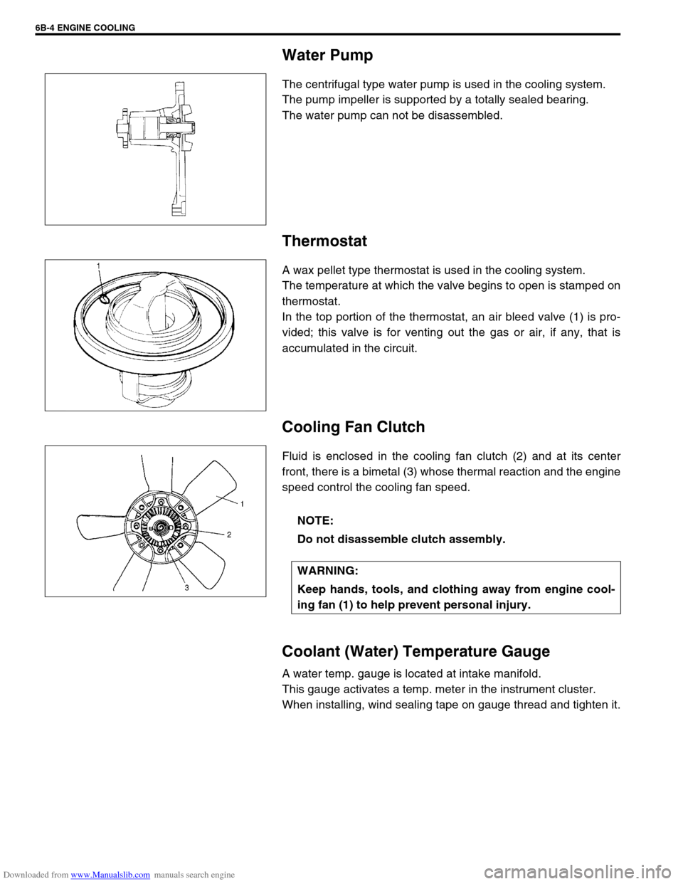
The centrifugal type water pump is used in the cooling system.
The pump impeller is supported by a totally sealed bearing.
The water pump can not be disassembled.
Thermostat
A wax pellet type thermostat is used in the cooling system.
The temperature at which the valve begins to open is stamped on
thermostat.
In the top portion of the thermostat, an air bleed valve (1) is pro-
vided; this valve is for venting out the gas or air, if any, that is
accumulated in the circuit.
Cooling Fan Clutch
Fluid is enclosed in the cooling fan clutch (2) and at its center
front, there is a bimetal (3) whose thermal reaction and the engine
speed control the cooling fan speed.
Coolant (Water) Temperature Gauge
A water temp. gauge is located at intake manifold.
This gauge activates a temp. meter in the instrument cluster.
When installing, wind sealing tape on gauge thread and tighten it.
NOTE:
Do not disassemble clutch assembly.
WARNING:
Keep hands, tools, and clothing away from engine cool-
ing fan (1) to help prevent personal injury.
Page 671 of 687

Downloaded from www.Manualslib.com manuals search engine 6H-4 CHARGING SYSTEM
When keeping battery on vehicle over a long period of time, follow
instructions given below.
Weekly, start the engine and run it until it reaches normal
operating temperature with engine speed of 2,000 to 3,000
rpm. Make sure all electric switches are off before storing the
vehicle.
Recharge the battery twice a month to prevent it from dis-
charging excessively. This is especially important when
ambient temperature is low.
The battery discharges even when it is not used, while vehi-
cles are being stored. Battery electrolyte can freeze and bat-
tery case can crack at cold ambient condition if battery is not
properly charged.
2) Keep the battery cable connections clean.
The cable connections, particularly at the positive (+) termi-
nal post, tend to become corroded. The product of corrosion,
or rust, on the mating faces of conductors resists the flow of
current.
Clean the terminals and fittings periodically to ensure good
metal-to-metal contact, and grease the connections after
each cleaning to protect them against rusting.
3) Be always in the know as to the state of charge of the bat-
tery. The simplest way to tell the state of charge is to carry
out a hydrometer test. The hydrometer is an instrument for
measuring the specific gravity (S.G.) of the battery electro-
lyte. The S.G. of the electrolyte is indicative of the state of
charge. Refer to “HYDROMETER TEST” in this section.
Generator
The generator is a small and high performance type with an IC regulator incorporated.
The internal components are connected electrically as shown below figure.
The generator features are as follows:
Solid state regulator is mounted inside the generator.
All regulator components are enclosed into a solid mold.
This unit along with the brush holder assembly is attached to the rear housing.
The IC regulator uses integrated circuits and controls the voltage produced by the generator, and the volt-
age setting cannot be adjusted.
The generator rotor bearings contain enough grease to eliminate the need for periodic lubrication. Two
brushes carry current through the two slip rings to the field coil mounted on the rotor, and under normal con-
ditions will provide long period of attention-free service.
The stator windings are assembled on the inside of a laminated core that forms part of the generator frame.
A condenser mounted in the rear housing suppresses radio noise.
Page 673 of 687

Downloaded from www.Manualslib.com manuals search engine 6H-6 CHARGING SYSTEM
Diagnosis
Battery
COMMON CAUSES OF FAILURE
A battery is not designed to last indefinitely; however, with proper
care, it will provide many years of service. If the battery performs
satisfactorily during test but fails to operate properly for no appar-
ent reason, the followings are some factors that may point to the
cause of trouble:
Accessories left on overnight or for an extended period with-
out the generator operating.
Slow average driving speeds for short periods.
Electrical load exceeding generator output particularly with
addition of after market equipment.
Defects in charging system such as high resistance, slipping
drive belt, loose generator output terminal, faulty generator
or voltage regulator. Refer to “Generator” in this “Diagnosis”
section.
Battery abuse, including failure to keep battery cable termi-
nals clean and tight or loose battery hold down.
Mechanical problems in electrical system such as shorted or
pinched wires.
VISUAL INSPECTION
Check for obvious damage, such as cracked or broken case or
cover, that could permit loss of electrolyte. If obvious damage is
noted, replace battery. Determine cause of damage and correct
as needed.
HYDROMETER TEST
The direct method of checking the battery for state of charge is to
carry out a high rate discharge test, which involves a special pre-
cise voltmeter and an expensive instrument used in the service
shops, but not recommendable to the user of the vehicle.
At 20 °C of battery temperature (electrolyte temperature):
The battery is in FULLY CHARGED STATE if the electrolyte
S.G. is 1.280.
The battery is in HALF CHARGED STATE if the S.G. is
1.220.
The battery is in NEARLY DISCHARGED STATE if the S.G.
is 1.150 and is in danger of freezing.
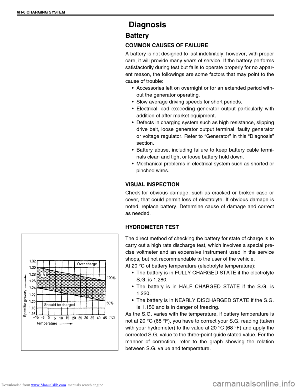
As the S.G. varies with the temperature, if battery temperature is
not at 20 °C (68 °F), you have to correct your S.G. reading (taken
with your hydrometer) to the value at 20 °C (68 °F) and apply the
corrected S.G. value to the three-point guide stated value. For the
manner of correction, refer to the graph showing the relation
between S.G. value and temperature.