Page 216 of 687
Downloaded from www.Manualslib.com manuals search engine FRONT SUSPENSION 3D-43
17) Tighten lateral rod (1) mounting bolt and nut to specified
torque.
Tightening torque
Lateral rod bolt and nut
(a) : 90 N·m (9.0 kg-m, 65.0 lb-ft)
18) Tighten right and left shock absorber lower mounting nuts
and leading arm mounting nuts to specified torque.
Tightening torque
Shock absorber lower nuts and leading arm nuts
(a) : 90 N·m (9.0 kg-m, 65.0 lb-ft)
19) Refill front axle (differential) housing with new specified gear
oil. Refer to “Maintenance Service” in Section 7E for refill.
20) Confirm front end (wheel) alignment referring to “Preliminary
Checks Prior to Adjusting Front Alignment” in Section 3A. NOTE:
When tightening bolt and nut, be sure that vehicle is off
hoist and in non loaded condition.
NOTE:
When tightening these nuts, be sure that vehicle is off
hoist and in non loaded condition.
1. Shock absorber
2. Leading arm
Page 217 of 687

Downloaded from www.Manualslib.com manuals search engine 3D-44 FRONT SUSPENSION
Tightening Torque Specifications
Required Service Material
Fastening partTightening torque
Nm kg-m lb-ft
Stabilizer mount bracket bolt 20 2.0 14.5
Stabilizer ball joint nut 50 5.0 36.5
Shock absorber lock nut 29 2.9 21.0
Shock absorber lower nut 90 9.0 65.0
Brake caliper carrier bolt 85 8.5 61.5
Wheel bearing lock nut 220 22.0 160.0
Wheel bearing lock washer screw 1.5 0.15 1.0
Air locking hub bolt 48 4.8 35.0
Wheel spindle bolt 50 5.0 36.5
Kingpin bolt 25 2.5 18.0
Knuckle seal cover bolt 10 1.0 7.5
Tie-rod end nut
43 4.3 31.5
Drag-rod end nut (Knuckle side)
Lateral rod bolt and nut
90 9.0 65.0
Leading arm nut
Front differential carrier bolt 23 2.3 17.0
Front propeller shaft flange bolt 50 5.0 36.5
Wheel nut 95 9.5 69.0
Vacuum pipe clamp bolt 5.5 0.55 4.0
MaterialRecommended SUZUKI product
(Part Number)Use
Lithium grease SUZUKI SUPER GREASE (A)
(99000-25010)Knuckle seal / axle shaft oil seal
Recess of wheel spindles
Wheel hub oil seal
Wheel bearing
Spindle thrust washer
Spindle bush (inside and flange
part)
Spindle oil seal
SUZUKI SUPER GREASE (C)
(99000-25030)Kingpin bearing
Axle shaft joint (for 4WD)
Sealant SUZUKI BOND NO. 1215
(99000-31110)Mating surfaces of wheel spindle
and knuckle
Mating surface of differential carrier
and axle housing
Sealing compound SUZUKI SEALING COMPOUND
366E
(99000-31090)Mating surface of wheel spindle and
knuckle
Kingpin
Mating surfaces of hub cap and
wheel hub
Page 241 of 687

Downloaded from www.Manualslib.com manuals search engine 3E-22 REAR SUSPENSION
Tightening Torque Specifications
Required Service Materials
Fastening portionTightening torque
Nm kg-m lb-ft
Shock absorber upper and lower bolt 85 8.5 61.5
Bump stopper 50 5.0 36.5
Lateral rod bolt and nut
90 9.0 65.0
Trailing arm nut (Front and Rear)
Brake back plate nut 23 2.3 17.0
Brake pipe flare nut 16 1.6 11.5
Rear differential carrier bolt 23 2.3 17.0
Rear propeller shaft bolt (Differential case side) 50 5.0 36.5
Rear propeller shaft bolt (Shaft No.3 transfer case side) 33 3.3 24.0
Wheel nut 95 9.5 69.0
Wheel speed sensor bolt and harness clamp bolt 10 1.0 7.5
MaterialRecommended SUZUKI product
(Part Number)Use
Lithium greaseSUZUKI SUPER GREASE A
(99000-25010)Oil seal lip
SealantSUZUKI BOND NO. 1215
(99000-31110)Joint seam of differential carrier and
axle housing
Water tight sealantSEALING COMPOUND 366E
(99000-31090)To apply to mating surfaces of brake
back plate and rear axle.
Gear oilFor gear oil information, refer to “Mainte-
nance Service” in Section 7E of this manual.Differential gear
(Rear axle housing)
Page 257 of 687

Downloaded from www.Manualslib.com manuals search engine 4B-4 PROPELLER SHAFTS
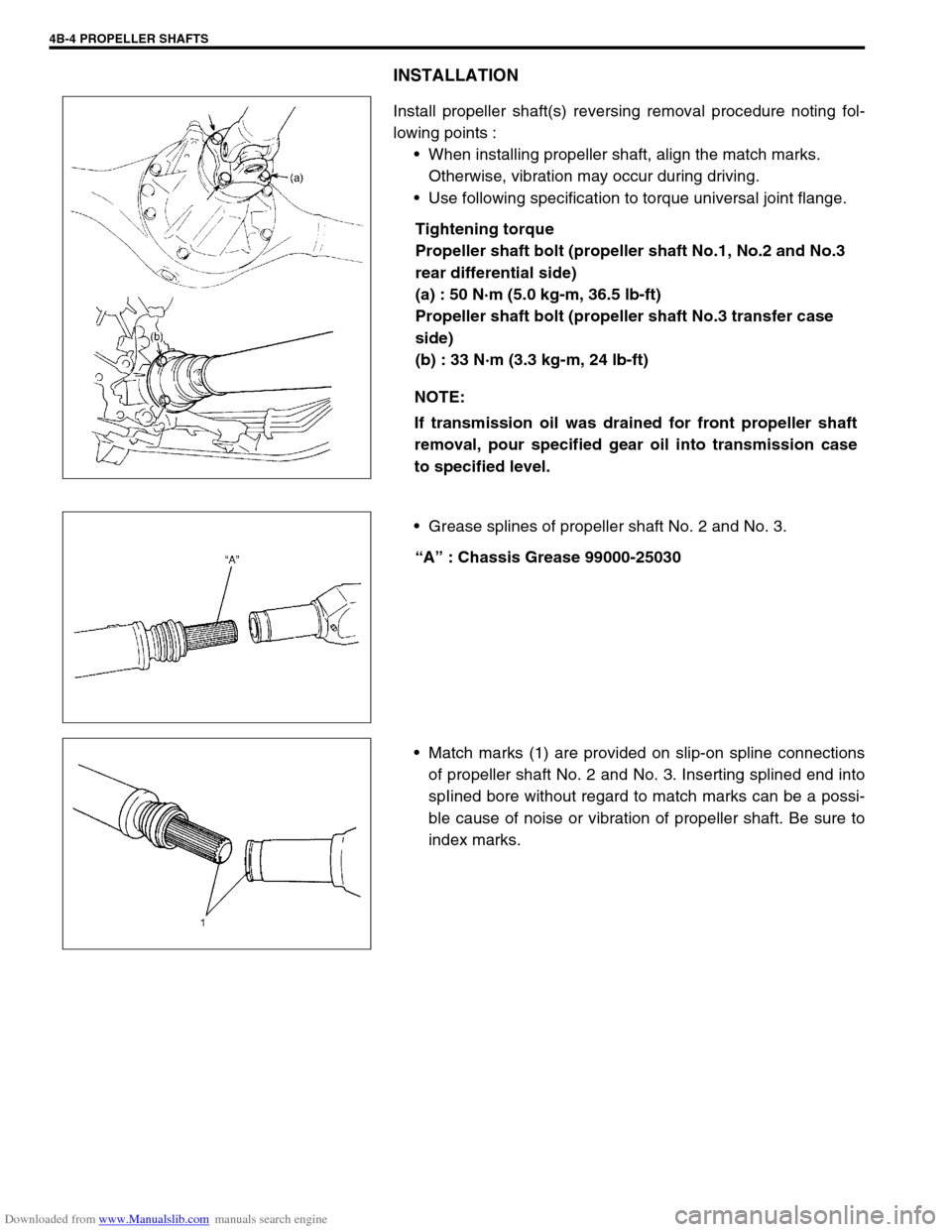
INSTALLATION
Install propeller shaft(s) reversing removal procedure noting fol-
lowing points :
When installing propeller shaft, align the match marks.
Otherwise, vibration may occur during driving.
Use following specification to torque universal joint flange.
Tightening torque
Propeller shaft bolt (propeller shaft No.1, No.2 and No.3
rear differential side)
(a) : 50 N·m (5.0 kg-m, 36.5 lb-ft)
Propeller shaft bolt (propeller shaft No.3 transfer case
side)
(b) : 33 N·m (3.3 kg-m, 24 lb-ft)
Grease splines of propeller shaft No. 2 and No. 3.
“A” : Chassis Grease 99000-25030
Match marks (1) are provided on slip-on spline connections
of propeller shaft No. 2 and No. 3. Inserting splined end into
spIined bore without regard to match marks can be a possi-
ble cause of noise or vibration of propeller shaft. Be sure to
index marks. NOTE:
If transmission oil was drained for front propeller shaft
removal, pour specified gear oil into transmission case
to specified level.