2005 SUZUKI JIMNY camshaft
[x] Cancel search: camshaftPage 392 of 687

Downloaded from www.Manualslib.com manuals search engine ENGINE GENERAL INFORMATION AND DIAGNOSIS 6-35
For TYPE B (See NOTE)
E1926 Manifold absolute pressure sensor 3.3 – 4.0 VIgnition switch ON
Barometric pressure : 100 kPa
(760 mmHg)
27 A/C evaporator temp. sensor 2.0 – 2.3 VIgnition switch ON A/C evaporation temp.
sensor at 25 °C (77 °F)
28EGR valve (stepper motor coil 4, if
equipped)10 – 14 VIgnition switch ON position leaving engine
OFF
29EGR valve (stepper motor coil 2, if
equipped)10 – 14 VIgnition switch ON position leaving engine
OFF
30–– –
31 Fuel injector NO.3 10 – 14 V Ignition switch ON TERMINAL
NO.CIRCUIT NORMAL
VOLTAGECONDITION
NOTE:
See NOTE in “ECM TERMINAL VOLTAGE VALUES TABLE” for applicable model.
TERMINAL
NO.CIRCUIT NORMAL
VOLTAGECONDITION
E191 Ground––
2 Ground––
3 Ground––
4 EVAP canister purge valve 10 – 14 V Ignition switch ON
5Power steering pressure switch
(if equipped)0 – 1.3 VWhile engine running at idle speed, turn
steering wheel to right or left as far as it
stops
10 – 14 V Ignition switch ON
6 Idle air control valve 0 – 13 VAt specified idle speed after engine
warmed up
7 Heater of HO2S-1 10 – 14 V Ignition switch ON
8 Fuel injector NO.4 10 – 14 V Ignition switch ON
9 Fuel injector NO.1 10 – 14 V Ignition switch ON
10 Sensor ground––
11 Camshaft position sensor0 – 0.8 V and
4 – 6 VIgnition switch ON
12–– –
13Heater oxygen sensor-1 Refer to DTC P0130 diag. flow table
CO adjusting resistor (w/o HO2S) 0 – 5 V Ignition switch ON position
14 Engine coolant temp. sensor 0.55 - 0.95 VIgnition switch ON
Engine coolant temp. : 80 °C (176 °F)
15 Intake air temp. sensor 2.0 – 2.7 VIgnition switch ON
Intake air temp. : 20 °C (68 °F)
16 Throttle opening signal0.2 – 1.0 VIgnition switch ON position and throttle
valve at idle position
2.8 – 4.8 VIgnition switch ON position and throttle
valve fully open
17EGR valve (stepper motor coil 3, if
equipped)10 – 14 VIgnition switch ON position leaving engine
OFF
Page 429 of 687

Downloaded from www.Manualslib.com manuals search engine 6-72 ENGINE GENERAL INFORMATION AND DIAGNOSIS
DTC P0300 Random Misfire Detected (Misfire Detected at 2 or More Cylinders)
DTC P0301 Cylinder 1 Misfire Detected
DTC P0302 Cylinder 2 Misfire Detected
DTC P0303 Cylinder 3 Misfire Detected
DTC P0304 Cylinder 4 Misfire Detected
CIRCUIT DESCRIPTION
ECM monitors crankshaft revolution speed and engine speed via the crankshaft position sensor and cylinder No.
via the camshaft position sensor. Then it calculates the change in the crankshaft revolution speed and from how
many times such change occurred in every 200 or 1000 engine revolutions, it detects occurrence of misfire.
When ECM detects a misfire (misfire rate per 200 revolutions) which can cause overheat and damage to the
three way catalytic converter, it makes the malfunction indicator lamp (MIL) flash as long as misfire occurs at
that rate.
After that, however, when the misfire rate drops, MIL remains ON until it has been judged as normal 3 times
under the same driving conditions.
Also, when ECM detects a misfire (misfire rate per 1000 revolutions) which will not cause damage to three way
catalytic converter but can cause exhaust emission to be deteriorated, it makes MIL light according to the 2 driv-
ing cycle detection logic.
1. Ignition coil assembly (for No.1 and No.4 cylinder)
2. Ignition coil assembly (for No.2 and No.3 cylinder)
3. Fuel injector
4. CKP sensor
5. CMP sensor
Page 439 of 687

Downloaded from www.Manualslib.com manuals search engine 6-82 ENGINE GENERAL INFORMATION AND DIAGNOSIS
DTC P0340 (DTC No.15) Camshaft Position (CMP) Sensor Circuit Malfunction
CIRCUIT DESCRIPTION
REFERENCE
Connect oscilloscope between terminals E19-11 of ECM connector connected to ECM and body ground and
check CMP sensor signal.
DTC CONFIRMATION PROCEDURE
1) Clear DTC.
2) Start engine and keep it at idle for 1 min.
3) Select “DTC” mode on scan tool and check DTC.
DTC DETECTING CONDITION POSSIBLE CAUSE
The number of CMP sensor signal pulses is incor-
rect during 8 revolution of crankshaft.CMP sensor circuit open or short.
Signal rotor teeth damaged.
CMP sensor malfunction, foreign material being
attached or improper installation.
ECM malfunction.
CMP sensor phase lag.
1. No.1 cylinder 3. No.3 cylinder [A] : Oscilloscope Waveforms [C] : CKP sensor waveform
2. No.2 cylinder 4. No.4 cylinder [B] : Waveforms at specified idle speed [D] : CMP sensor waveform
Page 482 of 687

Downloaded from www.Manualslib.com manuals search engine ENGINE MECHANICAL (M13 ENGINE) 6A1-1
6F1
6G
6H
6K
7A
7A1
7B1
7C1
7D
7E
7F
8A
8C
6A1
8E
9
9
10B
SECTION 6A1
ENGINE MECHANICAL (M13 ENGINE)
CONTENTS
General Description ......................................6A1-2
Engine ......................................................... 6A1-2
Engine Lubrication ...................................... 6A1-3
Diagnosis .......................................................6A1-4
Diagnosis Table .......................................... 6A1-4
Compression Check .................................... 6A1-4
Engine Vacuum Check ................................ 6A1-6
Oil Pressure Check ..................................... 6A1-7
Valve Lash (Clearance) ............................... 6A1-9
On-Vehicle Service......................................6A1-13
Air Cleaner Element .................................. 6A1-13
Air Cleaner Assembly ................................ 6A1-14
Knock Sensor ............................................ 6A1-14
Cylinder Head Cover ................................. 6A1-15
Throttle Body and Intake Manifold ............ 6A1-18
Exhaust Manifold ....................................... 6A1-21Oil Pan and Oil Pump Strainer .................. 6A1-24
Timing Chain Cover .................................. 6A1-28
Oil Pump ................................................... 6A1-33
Timing Chain and Chain Tensioner .......... 6A1-37
Camshaft, Tappet and Shim ..................... 6A1-42
Valves and Cylinder Head ........................ 6A1-48
Pistons, Piston Rings, Connecting
Rods and Cylinders................................... 6A1-62
Engine Mountings ..................................... 6A1-72
Unit Repair Overhaul .................................. 6A1-73
Engine Assembly ...................................... 6A1-73
Main Bearings, Crankshaft and Cylinder
Block ......................................................... 6A1-79
Required Service Material .......................... 6A1-93
Tightening Torque Specification ............... 6A1-93
Special Tool ................................................. 6A1-94
WARNING:
For vehicles equipped with Supplemental Restraint (Air Bag) System:
Service on and around the air bag system components or wiring must be performed only by an
authorized SUZUKI dealer. Refer to “Air Bag System Components and Wiring Location View” under
“General Description” in air bag system section in order to confirm whether you are performing ser-
vice on or near the air bag system components or wiring. Please observe all WARNINGS and “Ser-
vice Precautions” under “On-Vehicle Service” in air bag system section before performing service
on or around the air bag system components or wiring. Failure to follow WARNINGS could result in
unintentional activation of the system or could render the system inoperative. Either of these two
conditions may result in severe injury.
Technical service work must be started at least 90 seconds after the ignition switch is turned to the
“LOCK” position and the negative cable is disconnected from the battery. Otherwise, the system
may be activated by reserve energy in the Sensing and Diagnostic Module (SDM).
Page 483 of 687

Downloaded from www.Manualslib.com manuals search engine 6A1-2 ENGINE MECHANICAL (M13 ENGINE)
General Description
Engine
The engine is water-cooled, in line 4 cylinders, 4 stroke cycle gasoline unit with its DOHC (Double overhead
camshaft) valve mechanism arranged for “V” type valve configuration and 16 valves (4 valves / one cylinder).
The double overhead camshaft is mounted over the cylinder head; it is driven from crankshaft through timing
chain, and no push rods are provided in the valve train system.
Page 484 of 687

Downloaded from www.Manualslib.com manuals search engine ENGINE MECHANICAL (M13 ENGINE) 6A1-3
Engine Lubrication
The oil pump is of a trochoid type, and mounted under the crankshaft. Oil is drawn up through the oil pump
strainer and passed through the pump to the oil filter.
The filtered oil flows into 2 paths in cylinder block.
In one path, oil reaches the crankshaft journal bearings. Oil from the crankshaft journal bearings is supplied to
the connecting rod bearings by means of intersecting passages drilled in the crankshaft, and then injected from
the big end of connecting rod to lubricate piston, rings, and cylinder wall.
In other path oil goes up to the cylinder head and lubricates valves and camshafts, etc., after passing through
the internal oilway of camshafts.
An oil relief valve is provided on the oil pump. This valve starts relieving oil pressure when the pressure exceeds
about 400 kPa (4.0 kg/cm
2, 56.9 psi).
Page 490 of 687

Downloaded from www.Manualslib.com manuals search engine ENGINE MECHANICAL (M13 ENGINE) 6A1-9
Valve Lash (Clearance)
1) Remove negative cable at battery.
2) Remove cylinder head cover referring to “Cylinder Head
Cover” in this section.
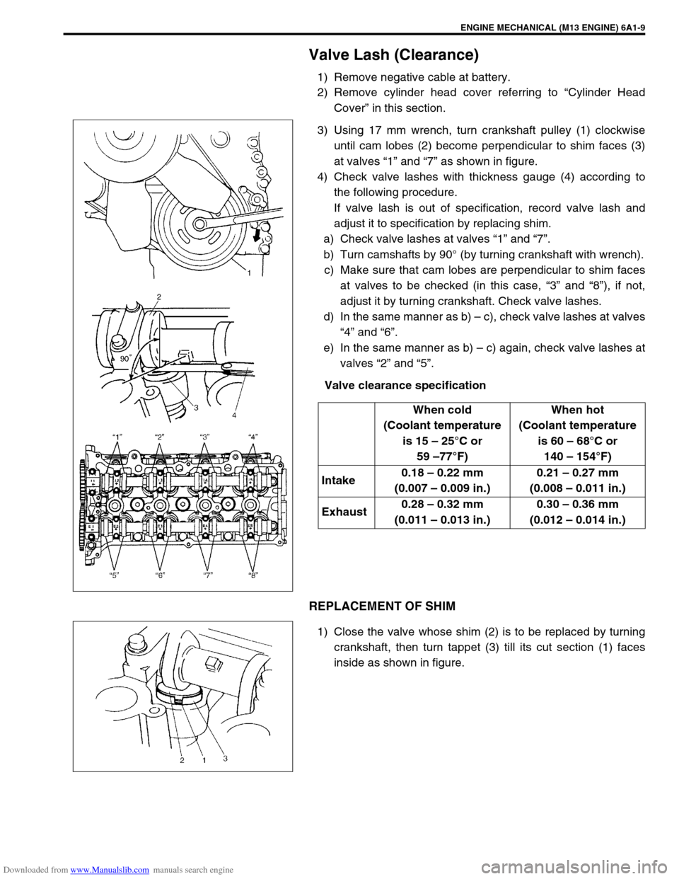
3) Using 17 mm wrench, turn crankshaft pulley (1) clockwise
until cam lobes (2) become perpendicular to shim faces (3)
at valves “1” and “7” as shown in figure.
4) Check valve lashes with thickness gauge (4) according to
the following procedure.
If valve lash is out of specification, record valve lash and
adjust it to specification by replacing shim.
a) Check valve lashes at valves “1” and “7”.
b) Turn camshafts by 90° (by turning crankshaft with wrench).
c) Make sure that cam lobes are perpendicular to shim faces
at valves to be checked (in this case, “3” and “8”), if not,
adjust it by turning crankshaft. Check valve lashes.
d) In the same manner as b) – c), check valve lashes at valves
“4” and “6”.
e) In the same manner as b) – c) again, check valve lashes at
valves “2” and “5”.
Valve clearance specification
REPLACEMENT OF SHIM
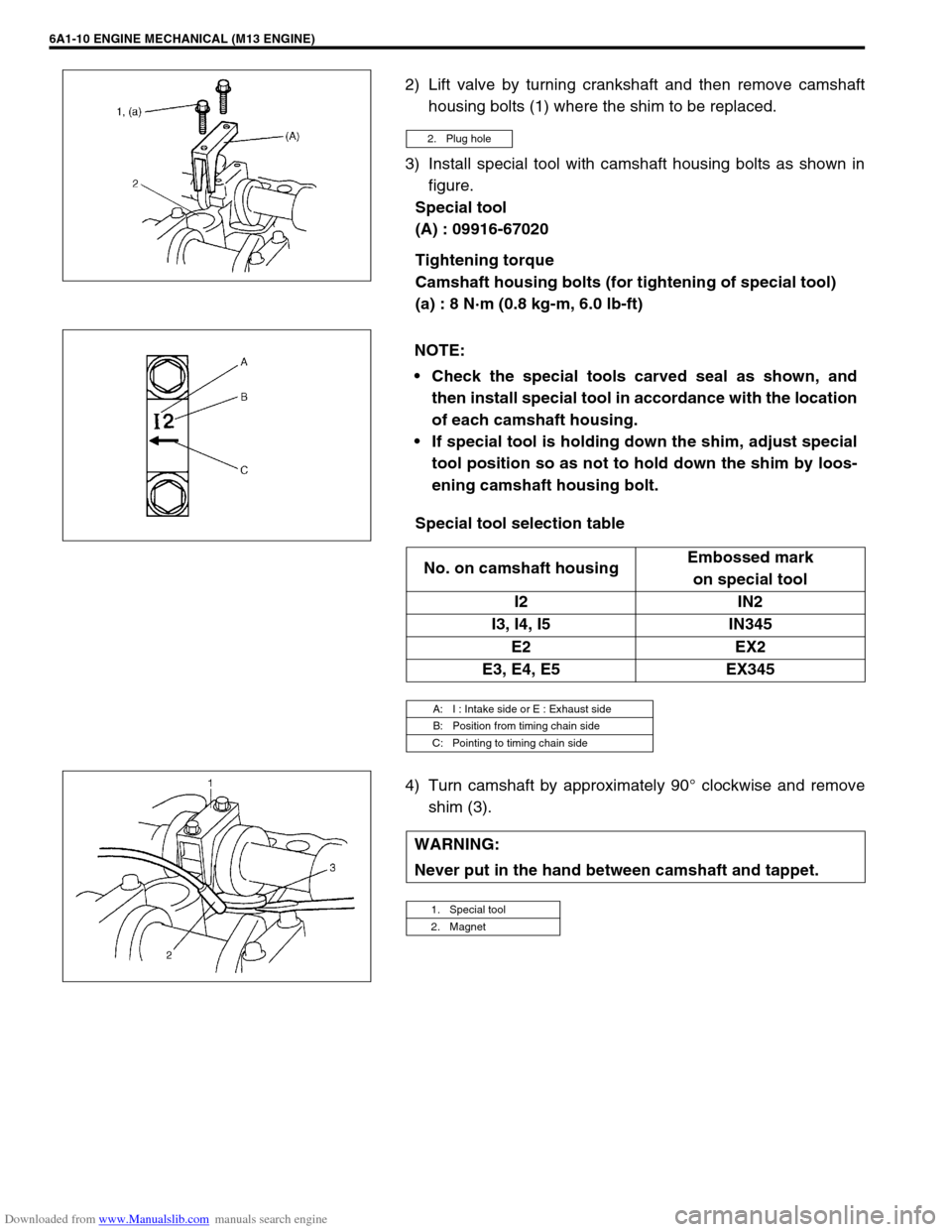
1) Close the valve whose shim (2) is to be replaced by turning
crankshaft, then turn tappet (3) till its cut section (1) faces
inside as shown in figure.When cold
(Coolant temperature
is 15 – 25°C or
59 –77°F)When hot
(Coolant temperature
is 60 – 68°C or
140 – 154°F)
Intake0.18 – 0.22 mm
(0.007 – 0.009 in.)0.21 – 0.27 mm
(0.008 – 0.011 in.)
Exhaust0.28 – 0.32 mm
(0.011 – 0.013 in.)0.30 – 0.36 mm
(0.012 – 0.014 in.)
Page 491 of 687

Downloaded from www.Manualslib.com manuals search engine 6A1-10 ENGINE MECHANICAL (M13 ENGINE)
2) Lift valve by turning crankshaft and then remove camshaft
housing bolts (1) where the shim to be replaced.
3) Install special tool with camshaft housing bolts as shown in
figure.
Special tool
(A) : 09916-67020
Tightening torque
Camshaft housing bolts (for tightening of special tool)
(a) : 8 N·m (0.8 kg-m, 6.0 lb-ft)
Special tool selection table
4) Turn camshaft by approximately 90° clockwise and remove
shim (3).
2. Plug hole
NOTE:
Check the special tools carved seal as shown, and
then install special tool in accordance with the location
of each camshaft housing.
If special tool is holding down the shim, adjust special
tool position so as not to hold down the shim by loos-
ening camshaft housing bolt.
No. on camshaft housingEmbossed mark
on special tool
I2 IN2
I3, I4, I5 IN345
E2 EX2
E3, E4, E5 EX345
A: I : Intake side or E : Exhaust side
B: Position from timing chain side
C: Pointing to timing chain side
WARNING:
Never put in the hand between camshaft and tappet.
1. Special tool
2. Magnet