Page 620 of 687
Downloaded from www.Manualslib.com manuals search engine ENGINE AND EMISSION CONTROL SYSTEM 6E-15
On-Vehicle Service
Accelerator cable adjustment
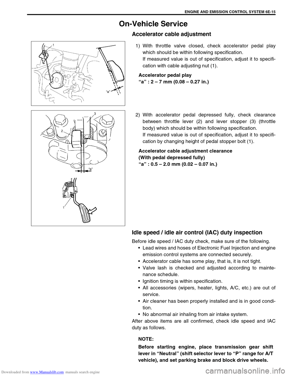
1) With throttle valve closed, check accelerator pedal play
which should be within following specification.
If measured value is out of specification, adjust it to specifi-
cation with cable adjusting nut (1).
Accelerator pedal play
“a” : 2 – 7 mm (0.08 – 0.27 in.)
2) With accelerator pedal depressed fully, check clearance
between throttle lever (2) and lever stopper (3) (throttle
body) which should be within following specification.
If measured value is out of specification, adjust it to specifi-
cation by changing height of pedal stopper bolt (1).
Accelerator cable adjustment clearance
(With pedal depressed fully)
“a” : 0.5 – 2.0 mm (0.02 – 0.07 in.)
Idle speed / idle air control (IAC) duty inspection
Before idle speed / IAC duty check, make sure of the following.
Lead wires and hoses of Electronic Fuel Injection and engine
emission control systems are connected securely.
Accelerator cable has some play, that is, it is not tight.
Valve lash is checked and adjusted according to mainte-
nance schedule.
Ignition timing is within specification.
All accessories (wipers, heater, lights, A/C, etc.) are out of
service.
Air cleaner has been properly installed and is in good condi-
tion.
No abnormal air inhaling from air intake system.
After above items are all confirmed, check idle speed and IAC
duty as follows.
NOTE:
Before starting engine, place transmission gear shift
lever in “Neutral” (shift selector lever to “P” range for A/T
vehicle), and set parking brake and block drive wheels.
Page 623 of 687
Downloaded from www.Manualslib.com manuals search engine 6E-18 ENGINE AND EMISSION CONTROL SYSTEM
Air Intake System
Throttle body
ON-VEHICLE INSPECTION
Check that throttle valve lever (1) moves smoothly.
REMOVAL
1) Disconnect negative cable at battery.
2) Drain cooling system.
3) Disconnect accelerator cable (1) from throttle valve lever.
1. Throttle body 4. Gasket 7. TP sensor screws
2. Throttle body gasket 5. Idle air control valve Tightening torque
3. TP sensor 6. IAC valve screws Do not reuse
Page 624 of 687
Downloaded from www.Manualslib.com manuals search engine ENGINE AND EMISSION CONTROL SYSTEM 6E-19
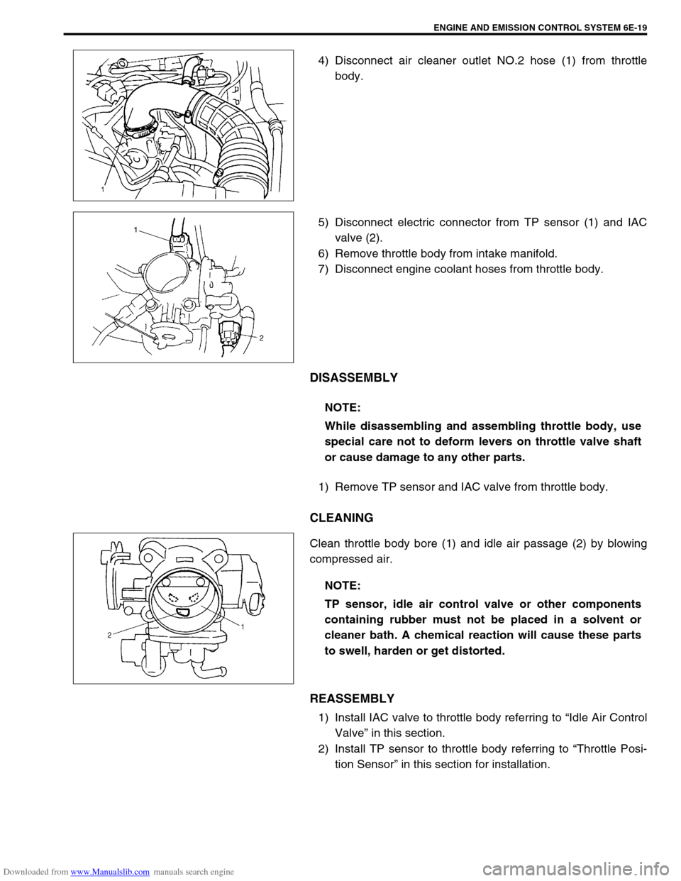
4) Disconnect air cleaner outlet NO.2 hose (1) from throttle
body.
5) Disconnect electric connector from TP sensor (1) and IAC
valve (2).
6) Remove throttle body from intake manifold.
7) Disconnect engine coolant hoses from throttle body.
DISASSEMBLY
1) Remove TP sensor and IAC valve from throttle body.
CLEANING
Clean throttle body bore (1) and idle air passage (2) by blowing
compressed air.
REASSEMBLY
1) Install IAC valve to throttle body referring to “Idle Air Control
Valve” in this section.
2) Install TP sensor to throttle body referring to “Throttle Posi-
tion Sensor” in this section for installation.
NOTE:
While disassembling and assembling throttle body, use
special care not to deform levers on throttle valve shaft
or cause damage to any other parts.
NOTE:
TP sensor, idle air control valve or other components
containing rubber must not be placed in a solvent or
cleaner bath. A chemical reaction will cause these parts
to swell, harden or get distorted.
Page 625 of 687
Downloaded from www.Manualslib.com manuals search engine 6E-20 ENGINE AND EMISSION CONTROL SYSTEM
INSTALLATION
1) Clean mating surfaces and install throttle body gasket to
intake manifold.
Use new gasket.
2) Connect engine coolant hoses.
3) Install throttle body (1) to intake manifold.
4) Connect connectors to TP sensor (2) and IAC valve (3)
securely.
5) Install air cleaner outlet No.2 hose (1) and pipe.
6) Connect accelerator cable and adjust cable play to specifica-
tion.
7) Refill cooling system.
8) Connect negative cable at battery.
Page 626 of 687
Downloaded from www.Manualslib.com manuals search engine ENGINE AND EMISSION CONTROL SYSTEM 6E-21
Idle air control valve (IAC valve)
REMOVAL
1) Remove throttle body from intake manifold referring to
“Throttle Body” in this section for removal.
2) Remove IAC valve from throttle body.
INSPECTION
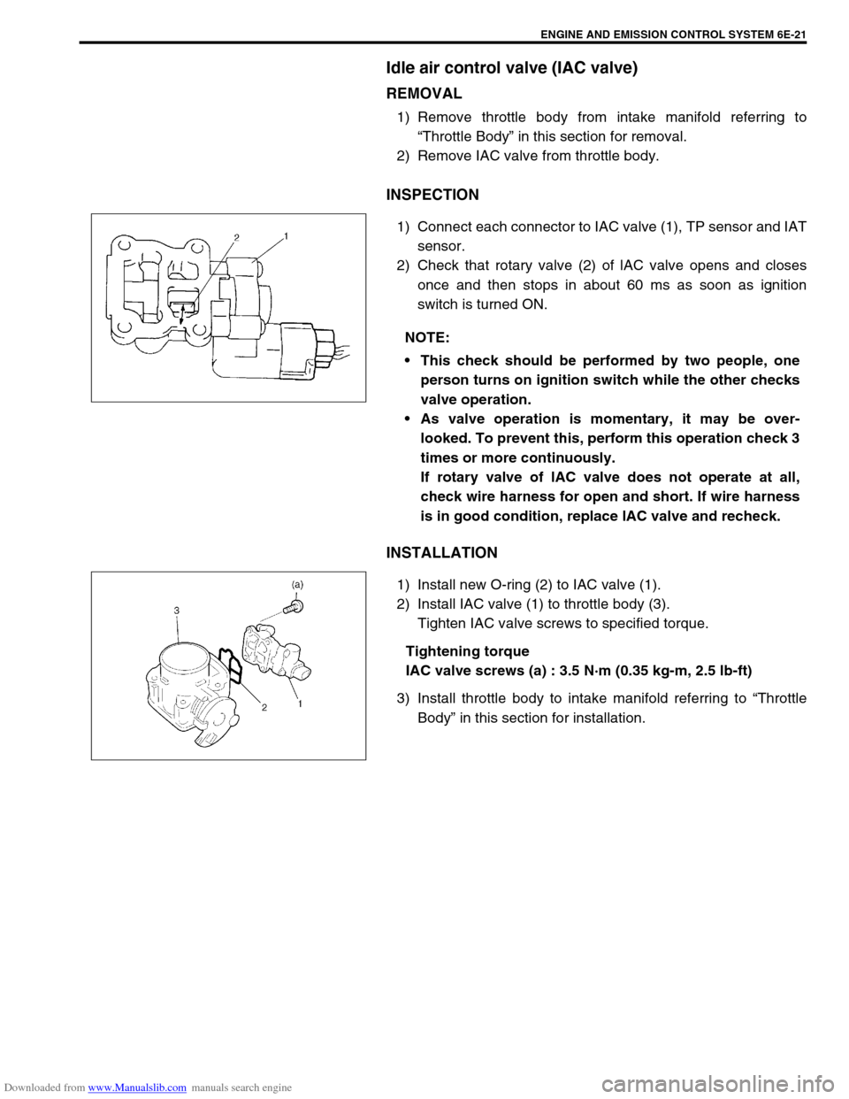
1) Connect each connector to IAC valve (1), TP sensor and IAT
sensor.
2) Check that rotary valve (2) of lAC valve opens and closes
once and then stops in about 60 ms as soon as ignition
switch is turned ON.
INSTALLATION
1) Install new O-ring (2) to IAC valve (1).
2) Install IAC valve (1) to throttle body (3).
Tighten IAC valve screws to specified torque.
Tightening torque
IAC valve screws (a) : 3.5 N·m (0.35 kg-m, 2.5 lb-ft)
3) Install throttle body to intake manifold referring to “Throttle
Body” in this section for installation. NOTE:
This check should be performed by two people, one
person turns on ignition switch while the other checks
valve operation.
As valve operation is momentary, it may be over-
looked. To prevent this, perform this operation check 3
times or more continuously.
If rotary valve of lAC valve does not operate at all,
check wire harness for open and short. If wire harness
is in good condition, replace lAC valve and recheck.
Page 635 of 687
Downloaded from www.Manualslib.com manuals search engine 6E-30 ENGINE AND EMISSION CONTROL SYSTEM
Throttle position sensor (TP sensor)
INSPECTION
1) Disconnect negative cable at battery and connector from TP
sensor.
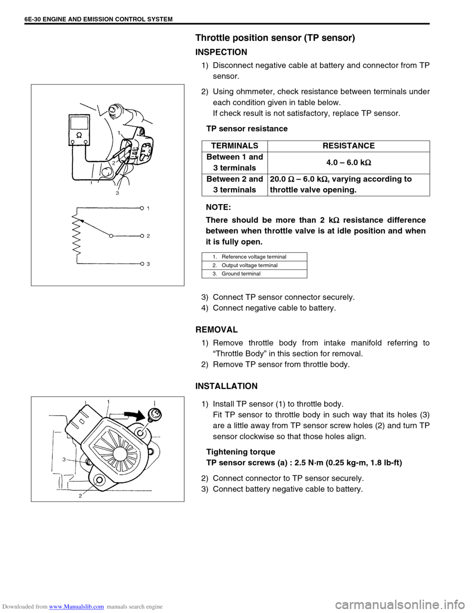
2) Using ohmmeter, check resistance between terminals under
each condition given in table below.
If check result is not satisfactory, replace TP sensor.
TP sensor resistance
3) Connect TP sensor connector securely.
4) Connect negative cable to battery.
REMOVAL
1) Remove throttle body from intake manifold referring to
“Throttle Body” in this section for removal.
2) Remove TP sensor from throttle body.
INSTALLATION
1) Install TP sensor (1) to throttle body.
Fit TP sensor to throttle body in such way that its holes (3)
are a little away from TP sensor screw holes (2) and turn TP
sensor clockwise so that those holes align.
Tightening torque
TP sensor screws (a) : 2.5 N·m (0.25 kg-m, 1.8 lb-ft)
2) Connect connector to TP sensor securely.
3) Connect battery negative cable to battery.TERMINALS RESISTANCE
Between 1 and
3 terminals4.0 – 6.0 k
Ω
ΩΩ Ω
Between 2 and
3 terminals20.0
Ω
ΩΩ Ω – 6.0 k
Ω
ΩΩ Ω, varying according to
throttle valve opening.
NOTE:
There should be more than 2 k
Ω
ΩΩ Ω resistance difference
between when throttle valve is at idle position and when
it is fully open.
1. Reference voltage terminal
2. Output voltage terminal
3. Ground terminal
Page 642 of 687
Downloaded from www.Manualslib.com manuals search engine ENGINE AND EMISSION CONTROL SYSTEM 6E-37
Fuel cut operation
INSPECTION
1) Warm up engine to normal operating temperature.
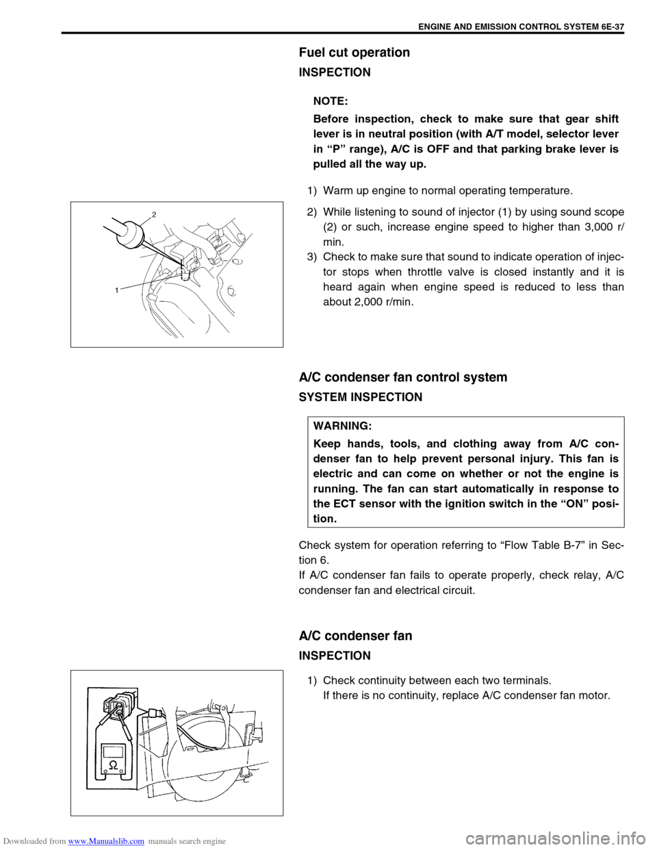
2) While listening to sound of injector (1) by using sound scope
(2) or such, increase engine speed to higher than 3,000 r/
min.
3) Check to make sure that sound to indicate operation of injec-
tor stops when throttle valve is closed instantly and it is
heard again when engine speed is reduced to less than
about 2,000 r/min.
A/C condenser fan control system
SYSTEM INSPECTION
Check system for operation referring to “Flow Table B-7” in Sec-
tion 6.
If A/C condenser fan fails to operate properly, check relay, A/C
condenser fan and electrical circuit.
A/C condenser fan
INSPECTION
1) Check continuity between each two terminals.
If there is no continuity, replace A/C condenser fan motor. NOTE:
Before inspection, check to make sure that gear shift
lever is in neutral position (with A/T model, selector lever
in “P” range), A/C is OFF and that parking brake lever is
pulled all the way up.
WARNING:
Keep hands, tools, and clothing away from A/C con-
denser fan to help prevent personal injury. This fan is
electric and can come on whether or not the engine is
running. The fan can start automatically in response to
the ECT sensor with the ignition switch in the “ON” posi-
tion.
Page 643 of 687
Downloaded from www.Manualslib.com manuals search engine 6E-38 ENGINE AND EMISSION CONTROL SYSTEM
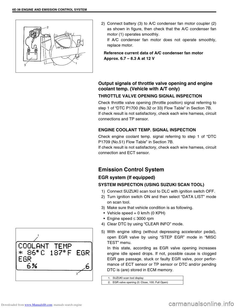
2) Connect battery (3) to A/C condenser fan motor coupler (2)
as shown in figure, then check that the A/C condenser fan
motor (1) operates smoothly.
If A/C condenser fan motor does not operate smoothly,
replace motor.
Reference current data of A/C condenser fan motor
Approx. 6.7 – 8.3 A at 12 V
Output signals of throttle valve opening and engine
coolant temp. (Vehicle with A/T only)
THROTTLE VALVE OPENING SIGNAL INSPECTION
Check throttle valve opening (throttle position) signal referring to
step 1 of “DTC P1700 (No.32 or 33) Flow Table” in Section 7B.
If check result is not satisfactory, check each wire harness, circuit
connections and TP sensor.
ENGINE COOLANT TEMP. SIGNAL INSPECTION
Check engine coolant temp. signal referring to step 1 of “DTC
P1709 (No.51) Flow Table” in Section 7B.
If check result is not satisfactory, check each wire harness, circuit
connection and ECT sensor.
Emission Control System
EGR system (If equipped)
SYSTEM INSPECTION (USING SUZUKI SCAN TOOL)
1) Connect SUZUKI scan tool to DLC with ignition switch OFF.
2) Turn ignition switch ON and then select “DATA LIST” mode
on scan tool.
3) Make sure that vehicle condition is as following.
Vehicle speed = 0 km/h (0 KPH)
Engine speed ≤ 3000 rpm
4) Clear DTC by using “CLEAR INFO” mode.
5) With engine idling (without depressing accelerator pedal),
open EGR valve by using “STEP EGR” mode in “MISC
TEST” menu.
In this state, according as EGR valve opening increases
engine idle speed drops. If not, possible cause is clogged
EGR gas passage, stuck or faulty EGR valve, poor perfor-
mance of ECT sensor or TP sensor or DTC and/or pending
DTC is (are) stored in ECM memory.
1. SUZUKI scan tool display
2. EGR valve opening (0: Close, 100: Full Open)