Page 288 of 687
Downloaded from www.Manualslib.com manuals search engine BRAKES 5-27
INSPECTION
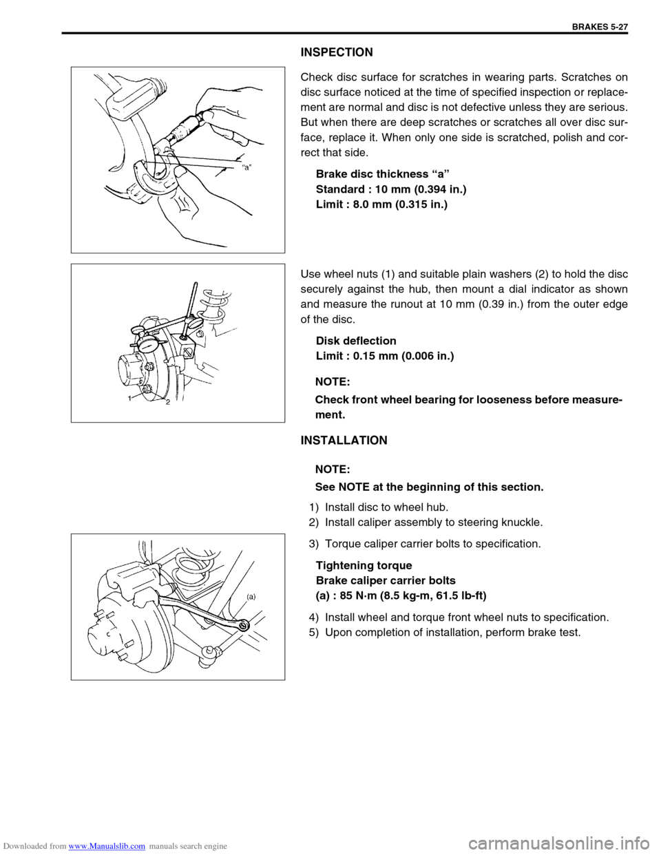
Check disc surface for scratches in wearing parts. Scratches on
disc surface noticed at the time of specified inspection or replace-
ment are normal and disc is not defective unless they are serious.
But when there are deep scratches or scratches all over disc sur-
face, replace it. When only one side is scratched, polish and cor-
rect that side.
Brake disc thickness “a”
Standard : 10 mm (0.394 in.)
Limit : 8.0 mm (0.315 in.)
Use wheel nuts (1) and suitable plain washers (2) to hold the disc
securely against the hub, then mount a dial indicator as shown
and measure the runout at 10 mm (0.39 in.) from the outer edge
of the disc.
Disk deflection
Limit : 0.15 mm (0.006 in.)
INSTALLATION
1) Install disc to wheel hub.
2) Install caliper assembly to steering knuckle.
3) Torque caliper carrier bolts to specification.
Tightening torque
Brake caliper carrier bolts
(a) : 85 N·m (8.5 kg-m, 61.5 lb-ft)
4) Install wheel and torque front wheel nuts to specification.
5) Upon completion of installation, perform brake test.
NOTE:
Check front wheel bearing for looseness before measure-
ment.
NOTE:
See NOTE at the beginning of this section.
Page 289 of 687
Downloaded from www.Manualslib.com manuals search engine 5-28 BRAKES
CHECK FOR FRONT BRAKE AFTER INSTALLATION
Mount tires and make certain that they rotate smoothly, with a
force of less than 3.0 kg (6.6 Ib).
If tire rotation is heavy, check the following:
Piston, piston seal and cylinder slide bush of caliper for
installation.
Wheel bearings for breakage.
Disc for flatness (Improper flatness brings disc into contact
with lining during rotation and makes rotation heavy).
To check this, measure disc deflection.NOTE:
For above check the following must be observed.
Jack up front wheels, both right and left, off the
ground.
Shift transfer shift lever to 2H (rear wheel) position (if
equipped) and start engine for a few seconds then
stop.
Side figure shows outer periphery of tire.
Be careful not to depress brake pedal when checking
tire for rotation.
1. String
2. Spring measure
Page 291 of 687
Downloaded from www.Manualslib.com manuals search engine 5-30 BRAKES
5) To increase clearance between brake shoe and brake drum,
remove rubber plug from brake back plate and turn adjuster
downward with flat-head screw driver.
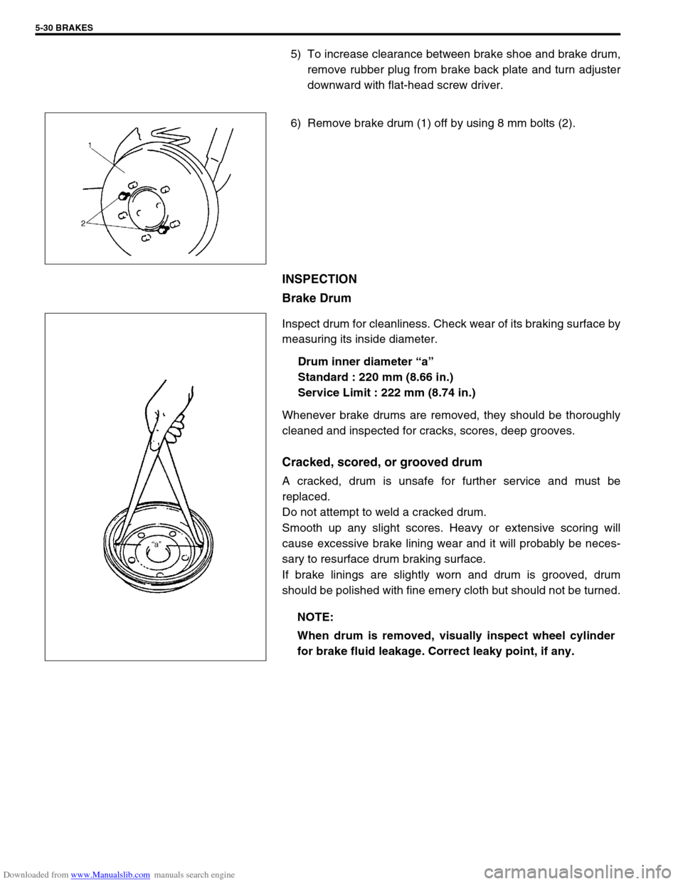
6) Remove brake drum (1) off by using 8 mm bolts (2).
INSPECTION
Brake Drum
Inspect drum for cleanliness. Check wear of its braking surface by
measuring its inside diameter.
Drum inner diameter “a”
Standard : 220 mm (8.66 in.)
Service Limit : 222 mm (8.74 in.)
Whenever brake drums are removed, they should be thoroughly
cleaned and inspected for cracks, scores, deep grooves.
Cracked, scored, or grooved drum
A cracked, drum is unsafe for further service and must be
replaced.
Do not attempt to weld a cracked drum.
Smooth up any slight scores. Heavy or extensive scoring will
cause excessive brake lining wear and it will probably be neces-
sary to resurface drum braking surface.
If brake linings are slightly worn and drum is grooved, drum
should be polished with fine emery cloth but should not be turned.
NOTE:
When drum is removed, visually inspect wheel cylinder
for brake fluid leakage. Correct leaky point, if any.
Page 292 of 687
Downloaded from www.Manualslib.com manuals search engine BRAKES 5-31
Brake Shoe
Where lining is worn out beyond service limit, replace shoe.
If one of brake linings is to service limit, all linings must be
replaced at the same time.
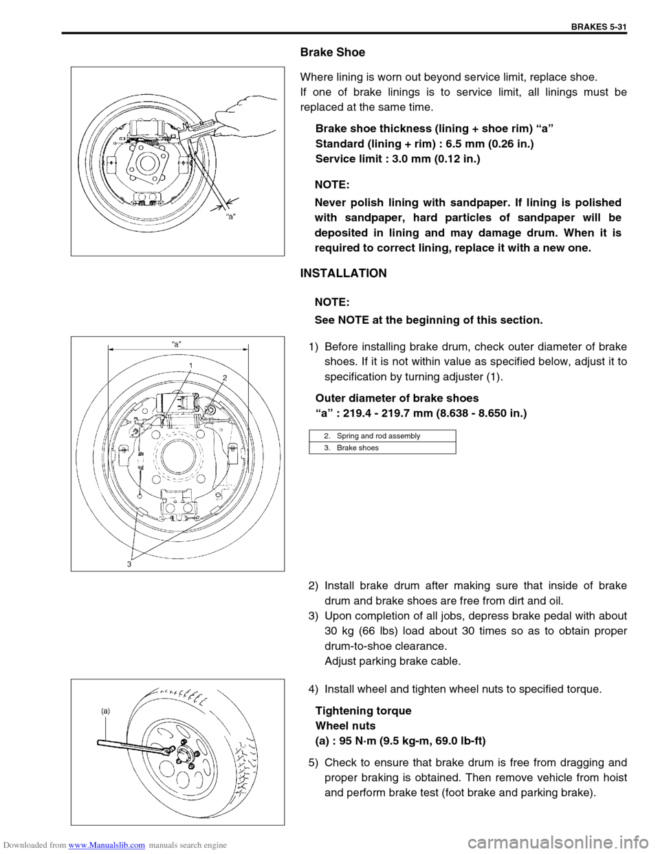
Brake shoe thickness (lining + shoe rim) “a”
Standard (lining + rim) : 6.5 mm (0.26 in.)
Service limit : 3.0 mm (0.12 in.)
INSTALLATION
1) Before installing brake drum, check outer diameter of brake
shoes. If it is not within value as specified below, adjust it to
specification by turning adjuster (1).
Outer diameter of brake shoes
“a” : 219.4 - 219.7 mm (8.638 - 8.650 in.)
2) Install brake drum after making sure that inside of brake
drum and brake shoes are free from dirt and oil.
3) Upon completion of all jobs, depress brake pedal with about
30 kg (66 lbs) load about 30 times so as to obtain proper
drum-to-shoe clearance.
Adjust parking brake cable.
4) Install wheel and tighten wheel nuts to specified torque.
Tightening torque
Wheel nuts
(a) : 95 N·m (9.5 kg-m, 69.0 lb-ft)
5) Check to ensure that brake drum is free from dragging and
proper braking is obtained. Then remove vehicle from hoist
and perform brake test (foot brake and parking brake). NOTE:
Never polish lining with sandpaper. If lining is polished
with sandpaper, hard particles of sandpaper will be
deposited in lining and may damage drum. When it is
required to correct lining, replace it with a new one.
NOTE:
See NOTE at the beginning of this section.
2. Spring and rod assembly
3. Brake shoes
Page 298 of 687
Downloaded from www.Manualslib.com manuals search engine BRAKES 5-37
INSTALLATION
1) When using new grommets, lubricate them with the same
fluid as the one to fill reservoir with. Then press-fit grommets
to master cylinder. Grommets must be seated in place.
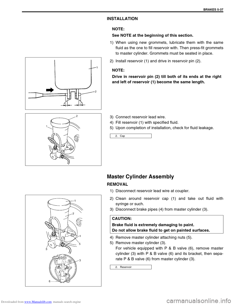
2) Install reservoir (1) and drive in reservoir pin (2).
3) Connect reservoir lead wire.
4) Fill reservoir (1) with specified fluid.
5) Upon completion of installation, check for fluid leakage.
Master Cylinder Assembly
REMOVAL
1) Disconnect reservoir lead wire at coupler.
2) Clean around reservoir cap (1) and take out fluid with
syringe or such.
3) Disconnect brake pipes (4) from master cylinder (3).
4) Remove master cylinder attaching nuts (5).
5) Remove master cylinder (3).
For vehicle equipped with P & B valve (6), remove master
cylinder (3) with P & B valve (6) and its bracket, then sepa-
rate P & B valve (6) from master cylinder (3). NOTE:
See NOTE at the beginning of this section.
NOTE:
Drive in reservoir pin (2) till both of its ends at the right
and left of reservoir (1) become the same length.
2. Cap
CAUTION:
Brake fluid is extremely damaging to paint.
Do not allow brake fluid to get on painted surfaces.
2. Reservoir
Page 299 of 687
Downloaded from www.Manualslib.com manuals search engine 5-38 BRAKES
INSTALLATION
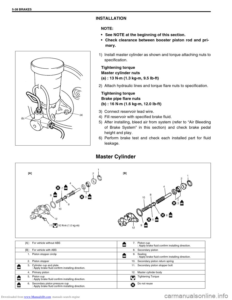
1) Install master cylinder as shown and torque attaching nuts to
specification.
Tightening torque
Master cylinder nuts
(a) : 13 N·m (1.3 kg-m, 9.5 Ib-ft)
2) Attach hydraulic lines and torque flare nuts to specification.
Tightening torque
Brake pipe flare nuts
(b) : 16 N·m (1.6 kg-m, 12.0 lb-ft)
3) Connect reservoir lead wire.
4) Fill reservoir with specified brake fluid.
5) After installing, bleed air from system (refer to “Air Bleeding
of Brake System” in this section) and check brake pedal
height and play.
6) Perform brake test and check each installed part for fluid
leakage.
Master Cylinder
NOTE:
See NOTE at the beginning of this section.
Check clearance between booster piston rod and pri-
mary.
[A] : For vehicle without ABS 7. Piston cup
: Apply brake fluid confirm installing direction.
[B] : For vehicle with ABS 8. Secondary piston
1. Piston stopper circlip 9. Sealing
: Apply brake fluid confirm installing direction.
2. Piston stopper 10. Secondary piston return spring
3. Cylinder cup and plate
: Apply brake fluid confirm installing direction.11. Secondary piston stopper bolt
4. Primary piston 12. Master cylinder body
5. Piston cup
: Apply brake fluid confirm installing direction.Tightening Torque
6. Secondary piston pressure cup
: Apply brake fluid confirm installing direction.Do not reuse
Page 303 of 687
Downloaded from www.Manualslib.com manuals search engine 5-42 BRAKES
LSPV (Load Sensing Proportioning Valve) Assembly (If Equipped)
REMOVAL
1) Clean around reservoir cap and take out fluid with syringe or
such.
2) Hoist vehicle.
3) Disconnect brake pipes from LSPV.
4) Remove LSPV assembly from vehicle.
5) Remove spring and stay from LSPV.
INSTALLATION
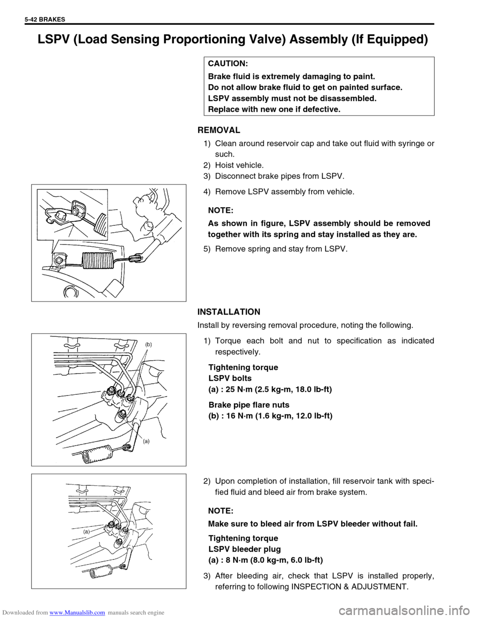
Install by reversing removal procedure, noting the following.
1) Torque each bolt and nut to specification as indicated
respectively.
Tightening torque
LSPV bolts
(a) : 25 N·m (2.5 kg-m, 18.0 lb-ft)
Brake pipe flare nuts
(b) : 16 N·m (1.6 kg-m, 12.0 lb-ft)
2) Upon completion of installation, fill reservoir tank with speci-
fied fluid and bleed air from brake system.
Tightening torque
LSPV bleeder plug
(a) : 8 N·m (8.0 kg-m, 6.0 lb-ft)
3) After bleeding air, check that LSPV is installed properly,
referring to following INSPECTION & ADJUSTMENT. CAUTION:
Brake fluid is extremely damaging to paint.
Do not allow brake fluid to get on painted surface.
LSPV assembly must not be disassembled.
Replace with new one if defective.
NOTE:
As shown in figure, LSPV assembly should be removed
together with its spring and stay installed as they are.
NOTE:
Make sure to bleed air from LSPV bleeder without fail.
Page 304 of 687
Downloaded from www.Manualslib.com manuals search engine BRAKES 5-43
LSPV Assembly
INSPECTION AND ADJUSTMENT
1) Confirm the following before inspection and adjustment.
Fuel tank is filled with fuel fully.
Vehicle is equipped with spare tire, tools, jack and jack han-
dle.
Vehicle is free from any other load.
Place it on level floor.
2) Push up LSPV lever with finger till it stops and measure
length of coil spring (“a” in figure).
3) Spring length “a” should be as specified.
Spring length “a”
147 mm (5.79 in.)
4) If it isn’t, adjust it to specification by changing stay position
as shown in figure. After adjustment, tighten bolt to specified
torque.
Tightening torque
LSPV adjust bolt
(a) : 25 N·m (2.5 kg-m, 18.0 lb-ft)
NOTE:
Check to make sure that LSPV body and brake pipe joints
are free from fluid leakage. Replace defective parts, if
any.