Page 197 of 687
Downloaded from www.Manualslib.com manuals search engine 3D-24 FRONT SUSPENSION
11) Using hydraulic press (1) and special tool remove wheel
bearing (2).
Special tool
(A) : 09913-75520
12) Remove hub bolts from hub.
INSTALLATION
1) Insert new stud in hub hole. Rotate stud slowly to assure ser-
rations are aligned with those made by original bolt.
2) Using special tool, press-fit wheel bearing (3) until its end
contacts stepped surface of wheel hub (4).
Special tool
(A) : 09944-78210
3) Install bearing circlip.
4) Drive in wheel bearing oil seal (1) by using special tools.
Special tool
(B) : 09944-66010
(C) : 09924-74510
1. Oil hydraulic press
2. Hub bolt
CAUTION:
Press-fit wheel bearing (3) vertically to hub (4).
1. Oil hydraulic press
2. Steel plate
Page 198 of 687

Downloaded from www.Manualslib.com manuals search engine FRONT SUSPENSION 3D-25
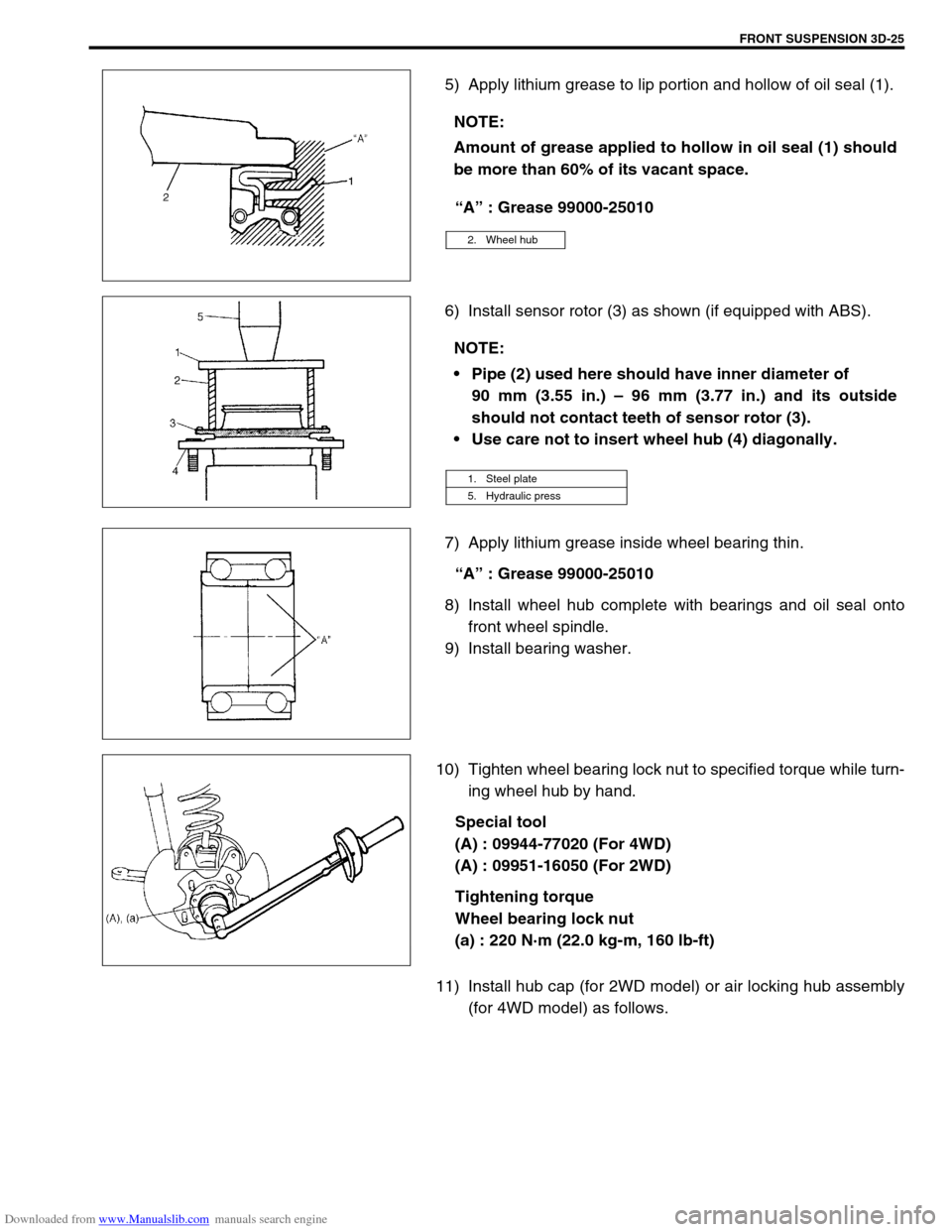
5) Apply lithium grease to lip portion and hollow of oil seal (1).
“A” : Grease 99000-25010
6) Install sensor rotor (3) as shown (if equipped with ABS).
7) Apply lithium grease inside wheel bearing thin.
“A” : Grease 99000-25010
8) Install wheel hub complete with bearings and oil seal onto
front wheel spindle.
9) Install bearing washer.
10) Tighten wheel bearing lock nut to specified torque while turn-
ing wheel hub by hand.
Special tool
(A) : 09944-77020 (For 4WD)
(A) : 09951-16050 (For 2WD)
Tightening torque
Wheel bearing lock nut
(a) : 220 N·m (22.0 kg-m, 160 lb-ft)
11) Install hub cap (for 2WD model) or air locking hub assembly
(for 4WD model) as follows. NOTE:
Amount of grease applied to hollow in oil seal (1) should
be more than 60% of its vacant space.
2. Wheel hub
NOTE:
Pipe (2) used here should have inner diameter of
90 mm (3.55 in.) – 96 mm (3.77 in.) and its outside
should not contact teeth of sensor rotor (3).
Use care not to insert wheel hub (4) diagonally.
1. Steel plate
5. Hydraulic press
Page 199 of 687

Downloaded from www.Manualslib.com manuals search engine 3D-26 FRONT SUSPENSION
For 2WD model:
a) Using lock plate (1), lock bearing lock nut. If lock screw hole
is not aligned with screw hole in lock nut, turn lock nut in
tightening direction till they align.
Tightening torque
Wheel bearing lock washer screw
(a) : 1.5 N·m (0.15 kg-m, 1.0 lb-ft)
b) Remove grease, old sealant and dusts from mating sur-
faces of hub cap (1) and wheel hub (2) to clean, apply
water tight sealant to hub cap mating surface evenly, and
install hub cap (1) to wheel hub (2).
“A” : Sealant 99000-31090
For 4WD model:
a) Caulk front wheel bearing lock nut at groove of spindle.
b) Apply lithium grease thinly to both surface, all around of
front spindle thrust washer (1).
“A” : Grease 99000-25010
NOTE:
When installing hub cap (1), hammer lightly several
locations on the collar of cap until collar comes closely
into contact with wheel hub (2).
If fitting part of cap is deformed or damaged or if it is
fitted loosely, replace with new one.
Page 203 of 687

Downloaded from www.Manualslib.com manuals search engine 3D-30 FRONT SUSPENSION
INSTALLATION
1) Set knuckle seal cover (2), knuckle seal (4) and knuckle seal
retainer (5) on front axle housing (6).
2) Apply grease within the knuckle (1). Amount of grease to be
applied within the knuckle (1) is approximately 100 g (for
4WD).
“A” : Grease 99000-25030
3) Apply grease to kingpin bearings (3) and install them to front
axle housing (6).
“A” : Grease 99000-25030
4) Apply sealant to indicated part of kingpin (1).
“A” : Sealant 99000-31090
5) Install steering knuckle (1) and king pins (2) and tighten king-
pin bolts to specified torque.
Tightening torque
Kingpin bolts
(a) : 25 N·m (2.5 kg-m, 18.0 lb-ft)
6) Apply grease to all around of knuckle seal lip.
“A” : Grease 99000-25010
7) Install knuckle seal retainer (1), knuckle seal (2) and knuckle
seal cover (3), tighten bolts to specified torque.
Tightening torque
Knuckle seal cover bolts
(a) : 10 N·m (1.0 kg-m, 7.5 lb-ft) NOTE:
When reusing bearing (3), install bearing (3) with sealing
at the top.
NOTE:
Install knuckle seal cover (3) and knuckle seal retainer (1)
so that their split section comes at the top as shown in
figure.
4. Steering knuckle 5. Split part
Page 204 of 687

Downloaded from www.Manualslib.com manuals search engine FRONT SUSPENSION 3D-31
8) Press-fit spindle bushing (2) to wheel spindle (1) by using
special tool.
Set cut part (4) of spindle bushing (2) as shown in figure
(opposite side of the groove (3) of wheel spindle).
Special tool
(A) : 09922-55131
9) Press-fit spindle oil seal (1) until it becomes flush with wheel
spindle (2) surface by using special tool, and then apply
grease to its lip.
Special tool
(A) : 09944-66020
10) Apply grease to spindle oil seal lip.
“A” : Grease 99000-25010
11) Apply grease to spindle bushing inside surface and flange
(2).
“A” : Grease 99000-25010
12) Install wheel spindle to knuckle, coat their mating surface
with sealant.
“B” : Sealant 99000-31110 or 99000-31090
13) Install wheel spindle (1) and disc dust cover (2) to steering
knuckle. Tighten wheel spindle bolts to specified torque.
Tightening torque
Wheel spindle bolts
(a) : 50 N·m (5.0 kg-m, 36.5 lb-ft)
CAUTION:
As this hole is a part of the passage of the vacuum that
activates the air locking hub, if it is clogged with grease,
the air locking hub cannot be locked or unlocked.
Therefore, be careful not to apply too much grease to
avoid clogging the vacuum passage.
Page 205 of 687

Downloaded from www.Manualslib.com manuals search engine 3D-32 FRONT SUSPENSION
14) Blow air into pipes at the top and the front of wheel spindle
and check that it comes out of the hole as shown in figure
(for 4WD).
15) Connect spindle vacuum hoses to wheel spindle (for 4WD).
16) Connect tie rod and drag rod to steering knuckle, refer to
“Tie rod and Drag Rod” in Section 3B.
17) Install wheel hub assembly, refer to “Wheel Hub / Bearing /
Oil Seal” in this section.
18) Install wheel and tighten wheel nuts to specified torque.
Tightening torque
Wheel nuts
: 95 N·m (9.5 kg-m, 69.0 lb-ft)
19) Lower hoist.
Front Axle Shaft / Oil Seal / Kingpin Bearing
Outer Race
REMOVAL
1) Hoist vehicle.
2) Drain differential gear oil from front axle housing by loosing
drain plug (for 4WD).
3) Remove steering knuckle. For details, refer to “Steering
Knuckle / Wheel Spindle” in this section.
4) Draw out axle shaft (2).CAUTION:
As this hole is a part of the passage of the vacuum that
activates the air locking hub, if it is clogged with grease,
the air locking hub cannot be locked or unlocked.
Therefore, be careful not to apply too much grease to
avoid clogging the vacuum passage.
1. Front axle housing
Page 208 of 687

Downloaded from www.Manualslib.com manuals search engine FRONT SUSPENSION 3D-35
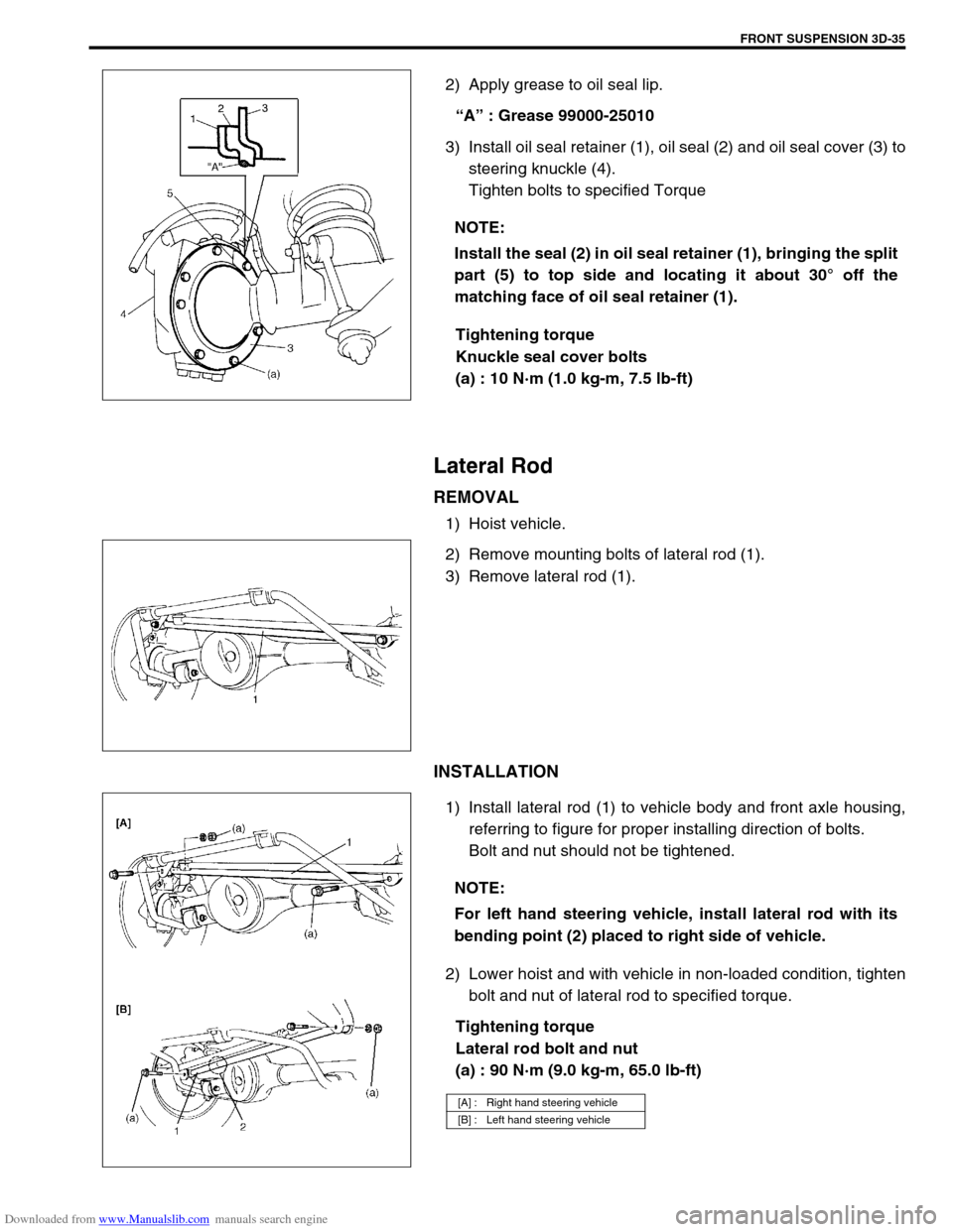
2) Apply grease to oil seal lip.
“A” : Grease 99000-25010
3) Install oil seal retainer (1), oil seal (2) and oil seal cover (3) to
steering knuckle (4).
Tighten bolts to specified Torque
Tightening torque
Knuckle seal cover bolts
(a) : 10 N·m (1.0 kg-m, 7.5 lb-ft)
Lateral Rod
REMOVAL
1) Hoist vehicle.
2) Remove mounting bolts of lateral rod (1).
3) Remove lateral rod (1).
INSTALLATION
1) Install lateral rod (1) to vehicle body and front axle housing,
referring to figure for proper installing direction of bolts.
Bolt and nut should not be tightened.
2) Lower hoist and with vehicle in non-loaded condition, tighten
bolt and nut of lateral rod to specified torque.
Tightening torque
Lateral rod bolt and nut
(a) : 90 N·m (9.0 kg-m, 65.0 lb-ft) NOTE:
Install the seal (2) in oil seal retainer (1), bringing the split
part (5) to top side and locating it about 30° off the
matching face of oil seal retainer (1).
NOTE:
For left hand steering vehicle, install lateral rod with its
bending point (2) placed to right side of vehicle.
[A] : Right hand steering vehicle
[B] : Left hand steering vehicle
Page 212 of 687

Downloaded from www.Manualslib.com manuals search engine FRONT SUSPENSION 3D-39
9) Remove knuckle seal cover bolts, take off knuckle seal cover
(1), knuckle seal and knuckle seal retainer.
10) Remove upper and lower kingpins (2) from steering knuckle.
11) Remove knuckle with hub assembly from axle housing (for
2WD model) or draw out right and left axle shafts with
knuckle and hub assembly (for 4WD model).
12) Before removing front propeller shaft (1), give match marks
(3) on joint flange (2) and front propeller shaft as shown (for
4WD).
13) Remove front differential from front axle housing (for 4WD).
14) Remove air locking hub vacuum pipe from axle housing (1)
(for 4WD).
15) Support front axle housing by using floor jack.
16) Remove lateral rod, refer to “Lateral Rod” in this section.
17) Remove stabilizer bar, refer to “Stabilizer Bar / Bushings” in
this section.
18) Loosen mounting nuts of leading arm (1) but don’t remove
bolts. NOTE:
The removed upper and lower kingpins (2) must be kept
separated so as to prevent an error when putting them
back in their place in reassembly.
NOTE:
At this time, lower kingpin bearing sometimes falls off.
So remove bearing while pulling off knuckle gradually.