Page 588 of 687
Downloaded from www.Manualslib.com manuals search engine ENGINE COOLING 6B-11
Coolant Draining
1) Remove radiator cap (1).
2) Loosen drain plug on radiator to drain coolant.
3) After draining coolant, be sure to tighten drain plug securely.
4) Fill cooling system. Refer to “Coolant” in this section.
Cooling Water Pipes or Hoses
REMOVAL
1) Drain cooling system.
2) To remove water pipes or hoses, loosen screw on each pipe
or hose clip and pull hose end off.
INSTALLATION
Install removed parts in reverse order of removal procedure, not-
ing the following.
Tighten each clamp bolt securely.
Refill cooling system with proper coolant, referring to
description on “Coolant” and “Cooling System Flush and
Refill” in this section.
Thermostat
REMOVAL
1) Drain cooling system and tighten drain plug.
2) Remove intake manifold, referring to “Throttle Body and
Intake Manifold” in Section 6A1.
3) Disconnect thermostat cap (1) from thermostat case (2).
4) Remove thermostat (3).
Page 589 of 687

Downloaded from www.Manualslib.com manuals search engine 6B-12 ENGINE COOLING
INSPECTION
1) Make sure that air bleed valve (1) of thermostat is clear.
Should this valve be clogged, engine would tend to overheat.
2) Check valve seat for some foreign matters being stuck which
prevent valve from seating tight.
3) Check thermostatic movement of wax pellet as follows:
a) Immerse thermostat (1) in water, and heat water gradually.
b) Check that valve starts to open at specification temp.
c) If valve starts to open at a temperature substantially below
or above, thermostat unit should be replaced with a new
one.
Such a unit, if re-used, will bring about overcooling or over-
heating tendency.
Thermostat functional specification
INSTALLATION
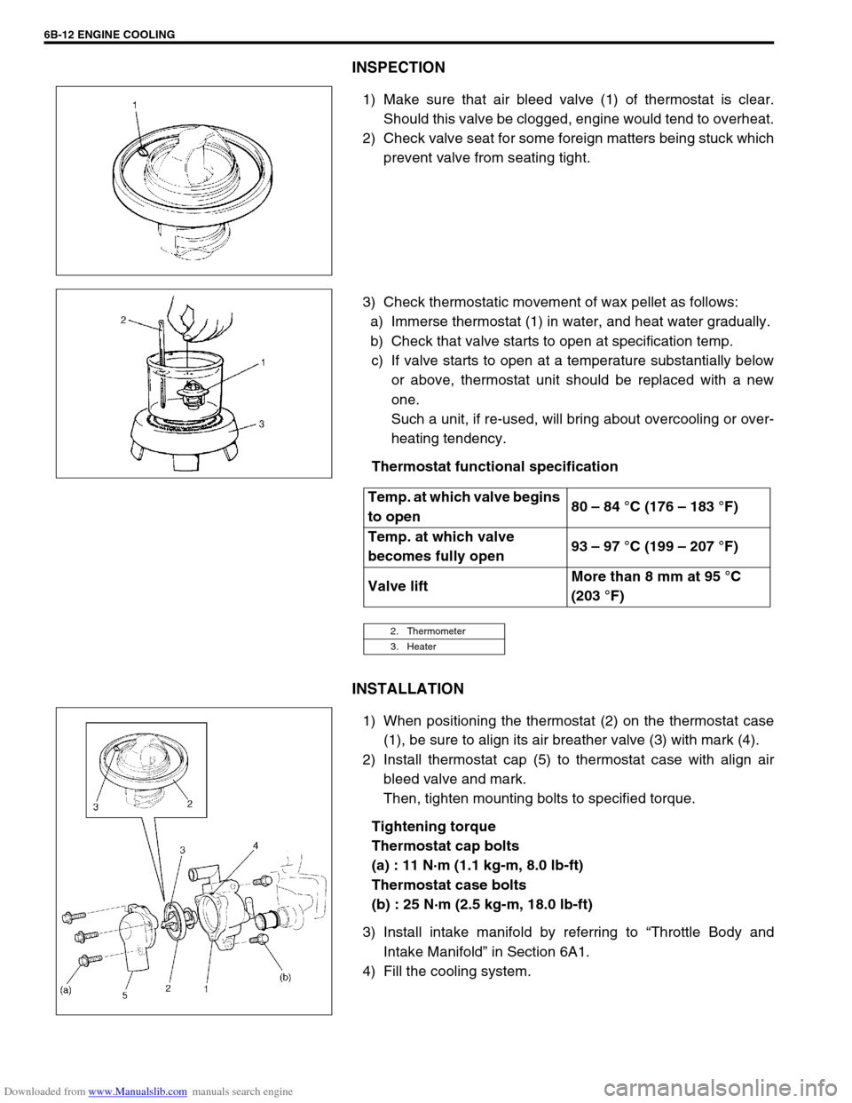
1) When positioning the thermostat (2) on the thermostat case
(1), be sure to align its air breather valve (3) with mark (4).
2) Install thermostat cap (5) to thermostat case with align air
bleed valve and mark.
Then, tighten mounting bolts to specified torque.
Tightening torque
Thermostat cap bolts
(a) : 11 N·m (1.1 kg-m, 8.0 lb-ft)
Thermostat case bolts
(b) : 25 N·m (2.5 kg-m, 18.0 lb-ft)
3) Install intake manifold by referring to “Throttle Body and
Intake Manifold” in Section 6A1.
4) Fill the cooling system.
Temp. at which valve begins
to open80 – 84 °C (176 – 183 °F)
Temp. at which valve
becomes fully open93 – 97 °C (199 – 207 °F)
Valve liftMore than 8 mm at 95 °C
(203 °F)
2. Thermometer
3. Heater
Page 641 of 687

Downloaded from www.Manualslib.com manuals search engine 6E-36 ENGINE AND EMISSION CONTROL SYSTEM
Vehicle speed sensor (VSS)
INSPECTION
Check vehicle speed sensor referring to step 7 of “DTC P0500
(No.16) Flow Table” in Section 6. If malfunction is found, replace.
Fuel level sensor (GAUGE)
INSPECTION
Refer to “Fuel Meter / Fuel Gauge Unit” in Section 8.
REMOVAL / INSTALLATION
Refer to “Fuel Pump Assembly” in Section 6C.
Knock sensor
INSPECTION
Check knock sensor referring to “DTC P0325 (No.17) Flow Table”
in Section 6. If malfunction is found, replace.
REMOVAL / INSTALLATION
Refer to “Knock Sensor” in Section 6A1.
Main relay, fuel pump relay and A/C condenser fan
control relay
INSPECTION
1) Disconnect negative cable at battery.
2) Remove main relay (1), fuel pump relay (2) and A/C con-
denser fan control relay (3) from vehicle.
3) Check that there is no continuity between terminal “A” and
“B”. If there is continuity, replace relay.
4) Connect battery positive (+) terminal to terminal “C” of relay.
Connect battery negative (–) terminal “D” of relay.
Check continuity between terminal “A” and “B”.
If there is no continuity when relay is connected to the bat-
tery, replace relay.
Page 687 of 687
Downloaded from www.Manualslib.com manuals search engine 6K-2 EXHAUST SYSTEM
On-Vehicle Service
COMPONENTS
Exhaust Manifold
REMOVAL AND INSTALLATION
Refer to “Exhaust Manifold” in Section 6A1 for removal and installation procedures of exhaust manifold.
INSPECTION
Check seals for deterioration or damage.
Exhaust Pipe
REMOVAL AND INSTALLATION
For replacement of exhaust pipe, exhaust center pipe, muffler or any parts used to mount or connect them, be
sure to hoist vehicle and observe WARNING under “Maintenance” and the following.
1. Exhaust pipe (Vehicle without TWC) 6. Gasket 11. Mounting nuts
2. Exhaust pipe (Vehicle with TWC) 7. Spring Tightening torque
3. Exhaust center pipe 8. Mounting Do not reuse.
4. Muffler 9. Oxygen sensor
5. Seal ring 10. Mounting bolts
CAUTION:
Exhaust pipe with three way catalytic converter should not be exposed to any impulse. Do not drop it
or hit it against something.