Page 574 of 687

Downloaded from www.Manualslib.com manuals search engine ENGINE MECHANICAL (M13 ENGINE) 6A1-93
Required Service Material
Tightening Torque Specification
MaterialRecommended SUZUKI product
(Part Number)Use
Sealant SUZUKI BOND NO. 1207C
(99000-31150)To apply to mating surface of cylinder block and oil
pan.
To apply to mating surface of cylinder block and
timing chain cover.
To apply to sealing surface of cylinder head cover.
To apply to mating surface to rear oil seal housing.
SUZUKI BOND NO. 1207B
(99000-31140)To apply to mating surface of cylinder block, cylin-
der head and timing chain cover.
SUZUKI BOND NO. 1215
(99000-31110)To flywheel (M/T) or drive plate (A/T) bolts.
Fastening partTightening torque
Nm kg-m lb-ft
Oil pressure switch 14.0 1.4 10.5
Camshaft housing bolts
(for replacement of shim)8.0 0.8 6.0
Camshaft housing bolts 11.0 1.1 8.0
Cylinder head cover bolts 8.0 0.8 6.0
Intake manifold bolts and nuts 25.0 2.5 18.0
Exhaust manifold bolts and nuts 55.0 5.5 40.0
Exhaust pipe bolts 50.0 5.0 36.5
Exhaust manifold stiffener bolts 50.0 5.0 36.5
Oil pump strainer bolt 11.0 1.1 8.0
Oil pump strainer bracket bolt 11.0 1.1 8.0
Oil pan bolts and nuts 11.0 1.1 8.0
Oil pan drain plug 50.0 5.0 36.5
Timing chain cover bolts and nut 23.0 2.3 17.0
Crankshaft pulley bolt 150.0 15.0 108.5
Oil pump rotor plate bolts 11.0 1.1 8.0
Timing chain No.1 guide bolts 9.0 0.9 6.5
Timing chain tensioner adjuster bolts 11.0 1.1 8.0
Venturi plug 5.0 0.5 3.5
Cylinder head bolt for M8 22.0 2.2 16.0
Cylinder head bolts for M10 a) Tighten 40 N·m
b) Turn 60°
c) Turn 60°a) Tighten 4.0 kg-m
b) Turn 60°
c) Turn 60°a) Tighten 29.0 lb-ft
b) Turn 60°
c) Turn 60°
Connecting rod bearing cap nuts a) Tighten 15 N·m
b) Turn 45°
c) Turn 45°a) Tighten 1.5 kg-m
b) Turn 45°
c) Turn 45°a) Tighten 11.0 lb-ft
b) Turn 45°
c) Turn 45°
Engine mounting bolts 50.0 5.0 36.5
Page 578 of 687

Downloaded from www.Manualslib.com manuals search engine ENGINE COOLING 6B-1
6B
SECTION 6B
ENGINE COOLING
CONTENTS
General Description ........................................6B-2
Cooling System Circulation ........................... 6B-2
Radiator Cap ................................................. 6B-3
Coolant Reservoir ......................................... 6B-3
Water Pump .................................................. 6B-4
Thermostat .................................................... 6B-4
Cooling Fan Clutch ........................................ 6B-4
Coolant (Water) Temperature Gauge............ 6B-4
Diagnosis .........................................................6B-5
Maintenance ....................................................6B-6
Coolant .......................................................... 6B-6
Coolant Level ................................................ 6B-7
Cooling System Service ................................ 6B-7Cooling System Flush and Refill ................... 6B-8
Water Pump Belt Tension ............................. 6B-9
On-Vehicle Service ....................................... 6B-10
Cooling System Component ....................... 6B-10
Coolant Draining ......................................... 6B-11
Cooling Water Pipes or Hoses .................... 6B-11
Thermostat .................................................. 6B-11
Water Pump Belt and Cooling Fan ............. 6B-13
Radiator ...................................................... 6B-14
Water Pump ................................................ 6B-15
Required Service Material ............................ 6B-17
Tightening Torque Specification ................. 6B-17
Page 584 of 687

Downloaded from www.Manualslib.com manuals search engine ENGINE COOLING 6B-7
Coolant Level
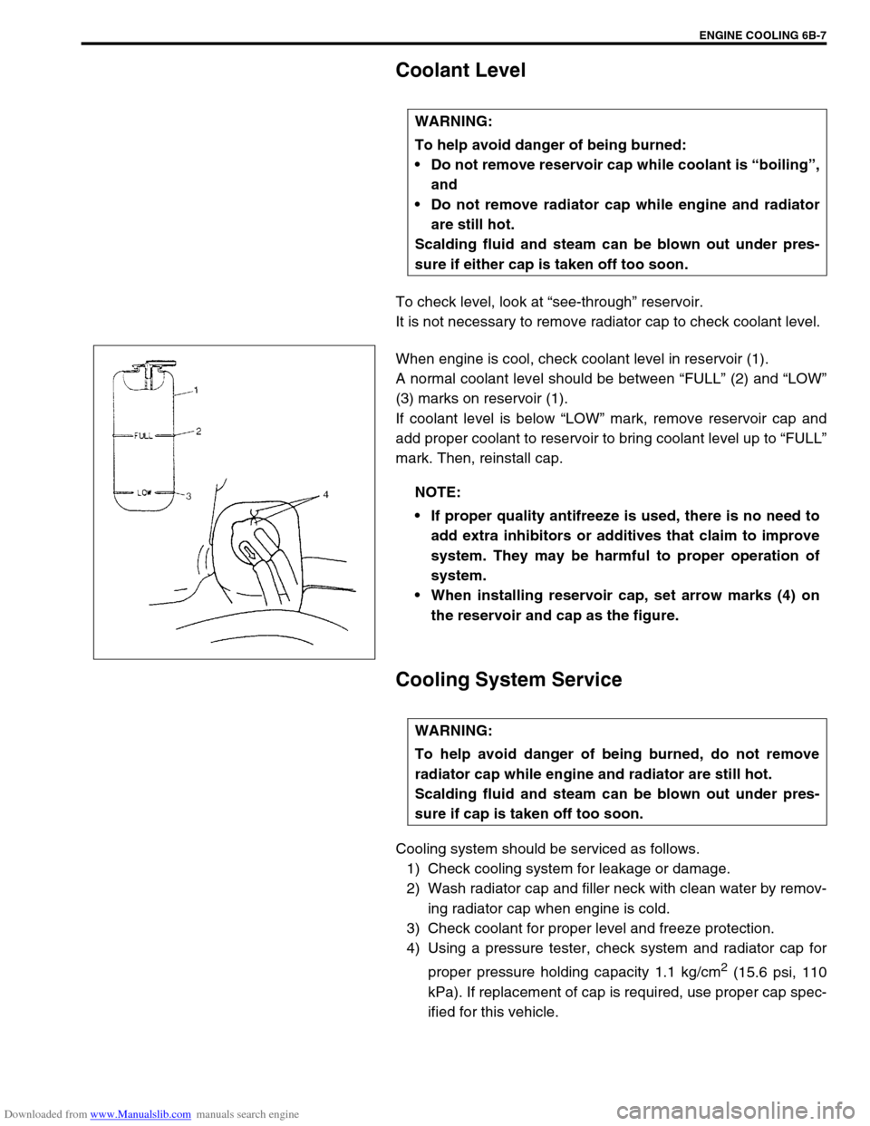
To check level, look at “see-through” reservoir.
It is not necessary to remove radiator cap to check coolant level.
When engine is cool, check coolant level in reservoir (1).
A normal coolant level should be between “FULL” (2) and “LOW”
(3) marks on reservoir (1).
If coolant level is below “LOW” mark, remove reservoir cap and
add proper coolant to reservoir to bring coolant level up to “FULL”
mark. Then, reinstall cap.
Cooling System Service
Cooling system should be serviced as follows.
1) Check cooling system for leakage or damage.
2) Wash radiator cap and filler neck with clean water by remov-
ing radiator cap when engine is cold.
3) Check coolant for proper level and freeze protection.
4) Using a pressure tester, check system and radiator cap for
proper pressure holding capacity 1.1 kg/cm
2 (15.6 psi, 110
kPa). If replacement of cap is required, use proper cap spec-
ified for this vehicle. WARNING:
To help avoid danger of being burned:
Do not remove reservoir cap while coolant is “boiling”,
and
Do not remove radiator cap while engine and radiator
are still hot.
Scalding fluid and steam can be blown out under pres-
sure if either cap is taken off too soon.
NOTE:
If proper quality antifreeze is used, there is no need to
add extra inhibitors or additives that claim to improve
system. They may be harmful to proper operation of
system.
When installing reservoir cap, set arrow marks (4) on
the reservoir and cap as the figure.
WARNING:
To help avoid danger of being burned, do not remove
radiator cap while engine and radiator are still hot.
Scalding fluid and steam can be blown out under pres-
sure if cap is taken off too soon.
Page 587 of 687
Downloaded from www.Manualslib.com manuals search engine 6B-10 ENGINE COOLING
On-Vehicle Service
Cooling System Component
CAUTION:
Check to make sure that engine coolant temperature is cold before removing any part of cooling
system.
Disconnect negative cable at battery before removing any part.
1. Radiator 6. Thermostat 11. Water outlet cap
2. Reservoir 7. Thermostat cap 12. Thermostat case outlet pipe
3. Cooling fan shroud 8. Radiator outlet pipe 13. Thermostat cap bolt
4. Water outlet pipe 9. Heater pipe 14. Thermostat case bolt
5. Thermostat case 10. ECT sensor Tightening Torque
814 25 N·m (2.5 kg-m) 10 15 N·m (1.5 kg-m)
12 5
6
7
13 11 N·m
(1.1 kg-m) 119421
3
Page 594 of 687
Downloaded from www.Manualslib.com manuals search engine ENGINE COOLING 6B-17
Required Service Material
Tightening Torque Specification
MaterialRecommended SUZUKI product
(Part Number)Use
Ethylene glycol base
coolant (Anti-freeze /
Anti-corrosion coolant)–Additive to engine cooling system for improving
cooling efficiency and for protection against
rusting.
SealantSUZUKI BOND NO.1207C
(99000 – 31150)To apply to water pump mating surface.
Fastening partTightening torque
Nm kg-m lb-ft
Water pump bolt 23 2.3 17.0
Thermostat cap bolt 11 1.1 8.0
Thermostat case bolt 25 2.5 18.0
Fun clutch bolt 11 1.1 8.0
Page 596 of 687

Downloaded from www.Manualslib.com manuals search engine ENGINE FUEL 6C-1
6F1
7A
7A1
7A
7A
7A1
7B1
7C1
7D
7E
7F
8A
8B
8C
6G
6C
6K
9
10
10A
10B
SECTION 6C
ENGINE FUEL
CONTENTS
General Description ....................................... 6C-2
Fuel System ................................................. 6C-2
Fuel Tank ..................................................... 6C-2
Fuel Pump Assembly ................................... 6C-3
Fuel Filler Cap .............................................. 6C-3
On-Vehicle Service......................................... 6C-4Fuel Lines .................................................... 6C-4
Fuel Filler Cap.............................................. 6C-4
Fuel Tank ..................................................... 6C-4
Fuel Pump Assembly ................................... 6C-7
Tightening Torque Specification ................ 6C-10
Special Tool .................................................. 6C-10
CAUTION:
For vehicles with a catalytic converter, be sure to use unleaded fuel only. Use of leaded and/or low
lead fuel can result in engine damage and reduce the effectiveness of the emission control system.
Page 599 of 687

Downloaded from www.Manualslib.com manuals search engine 6C-4 ENGINE FUEL
On-Vehicle Service
Before work, refer to “Precaution on Fuel System Service” in Sec-
tion 6.
Fuel Lines
Due to the fact that fuel feed line is under high pressure, use spe-
cial care when servicing it.
INSPECTION
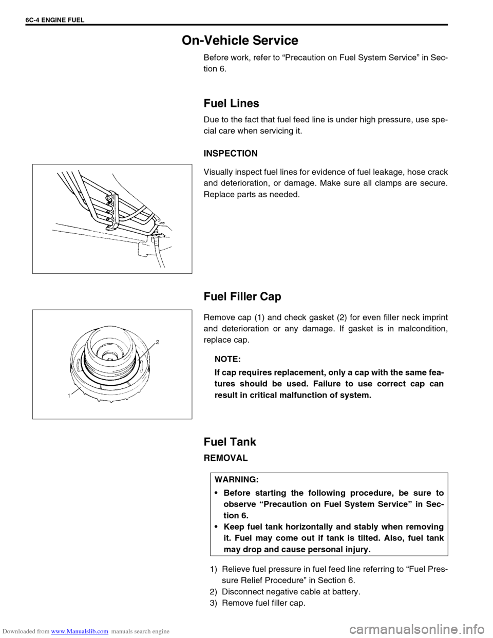
Visually inspect fuel lines for evidence of fuel leakage, hose crack
and deterioration, or damage. Make sure all clamps are secure.
Replace parts as needed.
Fuel Filler Cap
Remove cap (1) and check gasket (2) for even filler neck imprint
and deterioration or any damage. If gasket is in malcondition,
replace cap.
Fuel Tank
REMOVAL
1) Relieve fuel pressure in fuel feed line referring to “Fuel Pres-
sure Relief Procedure” in Section 6.
2) Disconnect negative cable at battery.
3) Remove fuel filler cap.
NOTE:
If cap requires replacement, only a cap with the same fea-
tures should be used. Failure to use correct cap can
result in critical malfunction of system.
WARNING:
Before starting the following procedure, be sure to
observe “Precaution on Fuel System Service” in Sec-
tion 6.
Keep fuel tank horizontally and stably when removing
it. Fuel may come out if tank is tilted. Also, fuel tank
may drop and cause personal injury.
Page 602 of 687

Downloaded from www.Manualslib.com manuals search engine ENGINE FUEL 6C-7
INSTALLATION
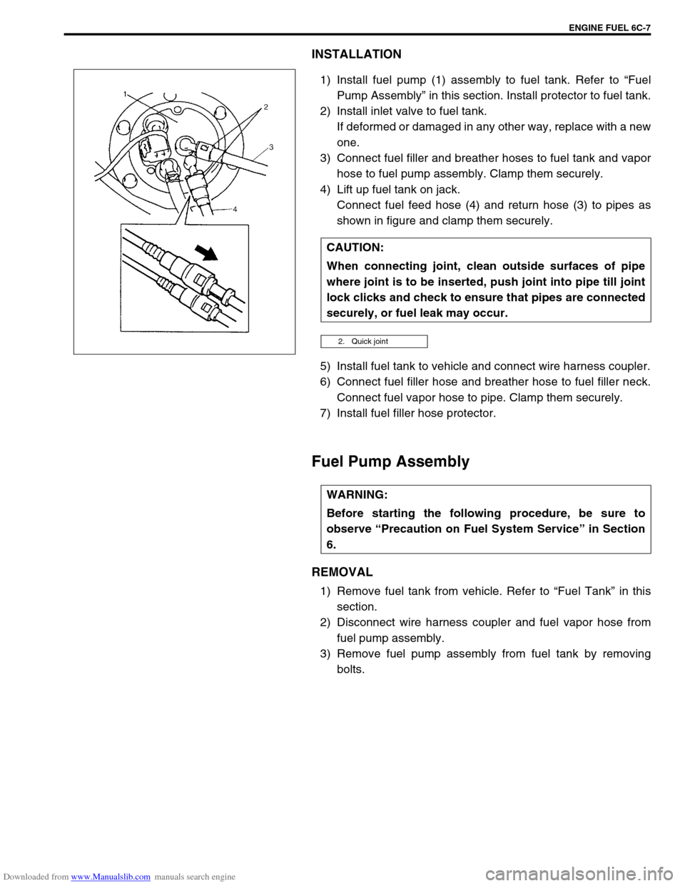
1) Install fuel pump (1) assembly to fuel tank. Refer to “Fuel
Pump Assembly” in this section. Install protector to fuel tank.
2) Install inlet valve to fuel tank.
If deformed or damaged in any other way, replace with a new
one.
3) Connect fuel filler and breather hoses to fuel tank and vapor
hose to fuel pump assembly. Clamp them securely.
4) Lift up fuel tank on jack.
Connect fuel feed hose (4) and return hose (3) to pipes as
shown in figure and clamp them securely.
5) Install fuel tank to vehicle and connect wire harness coupler.
6) Connect fuel filler hose and breather hose to fuel filler neck.
Connect fuel vapor hose to pipe. Clamp them securely.
7) Install fuel filler hose protector.
Fuel Pump Assembly
REMOVAL
1) Remove fuel tank from vehicle. Refer to “Fuel Tank” in this
section.
2) Disconnect wire harness coupler and fuel vapor hose from
fuel pump assembly.
3) Remove fuel pump assembly from fuel tank by removing
bolts. CAUTION:
When connecting joint, clean outside surfaces of pipe
where joint is to be inserted, push joint into pipe till joint
lock clicks and check to ensure that pipes are connected
securely, or fuel leak may occur.
2. Quick joint
WARNING:
Before starting the following procedure, be sure to
observe “Precaution on Fuel System Service” in Section
6.