2005 SUZUKI JIMNY crank
[x] Cancel search: crankPage 567 of 687

Downloaded from www.Manualslib.com manuals search engine 6A1-86 ENGINE MECHANICAL (M13 ENGINE)
4) From number stamped on crank web No.2 and alphabets
stamped on cylinder block, determine new standard bearing
to be installed to journal, by referring to table shown below.
For example, if number stamped on crank web No.2 is “1”
and alphabet stamped on cylinder block is “B”, install a new
standard bearing painted in “Purple” to its journal.
Specification of standard crankshaft main bearing
5) Using scale (1) on gauging plastic (2), check bearing clear-
ance with newly selected standard bearing.
If clearance still exceeds its limit, use next thicker bearing
and recheck clearance.
6) When replacing crankshaft or cylinder block due to any rea-
son, select new standard bearings to be installed by referring
to number stamped on new crankshaft or alphabets stamped
on new cylinder block.
UNDERSIZE BEARING (0.25 mm):
0.25 mm undersize bearing is available, in five kinds varying
in thickness.
To distinguish them, each bearing is painted in the following
colors at the center of bearing.
Each color represents the following thickness.
Undersize of crankshaft main bearingNumber stamped on crank web
No.2 (Journal diameter)
123
Alphabet
stamped on
cylinder block
(Cap bore dia.)APink Purple Brown
B Purple Brown Green
C Brown Green Black
New standard bearing to be
installed.
Color painted Bearing thickness
Red and Pink2.115 – 2.119 mm
(0.0833 – 0.0834 in.)
Red and Purple2.118 – 2.122 mm
(0.0834 – 0.0835 in.)
Red and Brown2.121 – 2.125 mm
(0.0835 – 0.0837 in.)
Red and Green2.124 – 2.128 mm
(0.0836 – 0.0838 in.)
Red and Black2.127 – 2.131 mm
(0.0837 – 0.0839 in.)
1. Paint
Page 568 of 687

Downloaded from www.Manualslib.com manuals search engine ENGINE MECHANICAL (M13 ENGINE) 6A1-87
If necessary, regrind crankshaft journal and select undersize
bearing to use with it as follows.
a) Regrind journal to the following finished diameter.
Finished diameter
44.732 – 44.750 mm (1.7611 – 1.7618 in.)
1) Using micrometer, measure reground journal diameter.
Measurement should be taken in two directions perpendicu-
lar to each other in order to check for out-of-round.
2) Using journal diameter measured above and alphabets
stamped on cylinder block, select an undersize bearing by
referring to table given below.
Check bearing clearance with newly selected undersize
bearing.
Specification of undersize crankshaft main bearing
Rear Oil Seal
Carefully inspect oil seal (1) for wear or damage.
If its lip is worn or damaged, replace it.
For oil seal installation, press-fit rear oil seal (1) to oil seal hous-
ing (2) by using special tool as shown in the figure.
Special tool
(A) : 09911-97820
Crank rear oil seal installing position
“a” : 3 mm (0.12 in.)
Measured journal diameter
44.744 – 44.750 mm
(1.7616 – 1.7618 in.)44.738 – 44.744 mm
(1.7613 – 1.7616 in.)44.732 – 44.738 mm
(1.7611 – 1.7613 in.)
Alphabets stamped
on cylinder blockA Red and Pink Red and Purple Red and Brown
B Red and Purple Red and Brown Red and Green
C Red and Brown Red and Green Red and Black
Undersize bearing to be installed
Page 571 of 687

Downloaded from www.Manualslib.com manuals search engine 6A1-90 ENGINE MECHANICAL (M13 ENGINE)
INSTALLATION
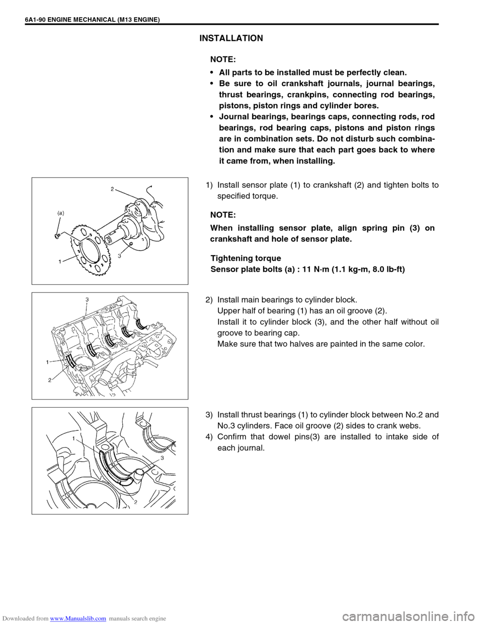
1) Install sensor plate (1) to crankshaft (2) and tighten bolts to
specified torque.
Tightening torque
Sensor plate bolts (a) : 11 N·m (1.1 kg-m, 8.0 lb-ft)
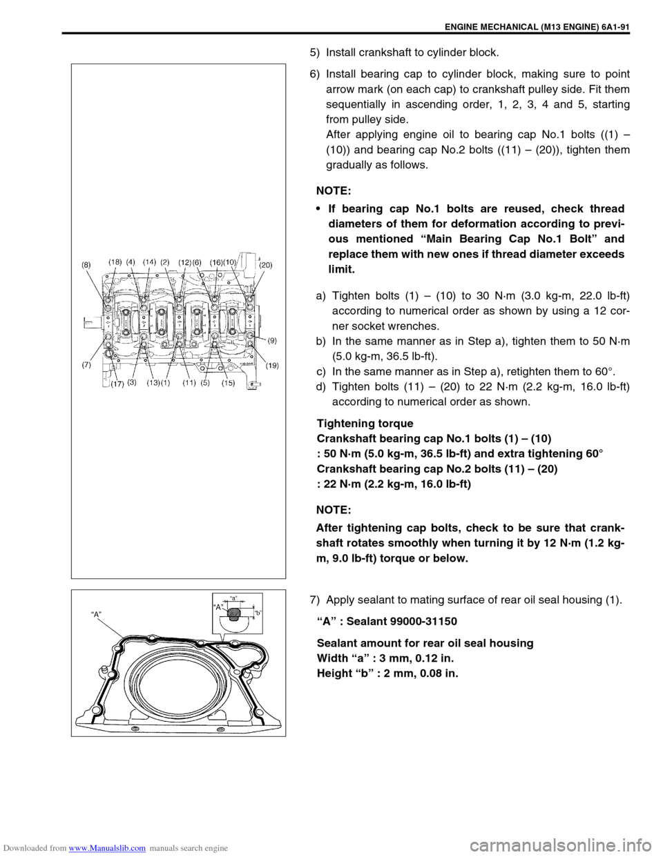
2) Install main bearings to cylinder block.
Upper half of bearing (1) has an oil groove (2).
Install it to cylinder block (3), and the other half without oil
groove to bearing cap.
Make sure that two halves are painted in the same color.
3) Install thrust bearings (1) to cylinder block between No.2 and
No.3 cylinders. Face oil groove (2) sides to crank webs.
4) Confirm that dowel pins(3) are installed to intake side of
each journal. NOTE:
All parts to be installed must be perfectly clean.
Be sure to oil crankshaft journals, journal bearings,
thrust bearings, crankpins, connecting rod bearings,
pistons, piston rings and cylinder bores.
Journal bearings, bearings caps, connecting rods, rod
bearings, rod bearing caps, pistons and piston rings
are in combination sets. Do not disturb such combina-
tion and make sure that each part goes back to where
it came from, when installing.
NOTE:
When installing sensor plate, align spring pin (3) on
crankshaft and hole of sensor plate.
Page 572 of 687

Downloaded from www.Manualslib.com manuals search engine ENGINE MECHANICAL (M13 ENGINE) 6A1-91
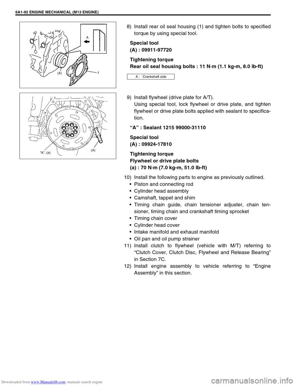
5) Install crankshaft to cylinder block.
6) Install bearing cap to cylinder block, making sure to point
arrow mark (on each cap) to crankshaft pulley side. Fit them
sequentially in ascending order, 1, 2, 3, 4 and 5, starting
from pulley side.
After applying engine oil to bearing cap No.1 bolts ((1) –
(10)) and bearing cap No.2 bolts ((11) – (20)), tighten them
gradually as follows.
a) Tighten bolts (1) – (10) to 30 N·m (3.0 kg-m, 22.0 lb-ft)
according to numerical order as shown by using a 12 cor-
ner socket wrenches.
b) In the same manner as in Step a), tighten them to 50 N·m
(5.0 kg-m, 36.5 lb-ft).
c) In the same manner as in Step a), retighten them to 60°.
d) Tighten bolts (11) – (20) to 22 N·m (2.2 kg-m, 16.0 lb-ft)
according to numerical order as shown.
Tightening torque
Crankshaft bearing cap No.1 bolts (1) – (10)
: 50 N·m (5.0 kg-m, 36.5 lb-ft) and extra tightening 60°
Crankshaft bearing cap No.2 bolts (11) – (20)
: 22 N·m (2.2 kg-m, 16.0 lb-ft)
7) Apply sealant to mating surface of rear oil seal housing (1).
“A” : Sealant 99000-31150
Sealant amount for rear oil seal housing
Width “a” : 3 mm, 0.12 in.
Height “b” : 2 mm, 0.08 in. NOTE:
If bearing cap No.1 bolts are reused, check thread
diameters of them for deformation according to previ-
ous mentioned “Main Bearing Cap No.1 Bolt” and
replace them with new ones if thread diameter exceeds
limit.
NOTE:
After tightening cap bolts, check to be sure that crank-
shaft rotates smoothly when turning it by 12 N·m (1.2 kg-
m, 9.0 lb-ft) torque or below.
Page 573 of 687

Downloaded from www.Manualslib.com manuals search engine 6A1-92 ENGINE MECHANICAL (M13 ENGINE)
8) Install rear oil seal housing (1) and tighten bolts to specified
torque by using special tool.
Special tool
(A) : 09911-97720
Tightening torque
Rear oil seal housing bolts : 11 N·m (1.1 kg-m, 8.0 lb-ft)
9) Install flywheel (drive plate for A/T).
Using special tool, lock flywheel or drive plate, and tighten
flywheel or drive plate bolts applied with sealant to specifica-
tion.
“A” : Sealant 1215 99000-31110
Special tool
(A) : 09924-17810
Tightening torque
Flywheel or drive plate bolts
(a) : 70 N·m (7.0 kg-m, 51.0 lb-ft)
10) Install the following parts to engine as previously outlined.
Piston and connecting rod
Cylinder head assembly
Camshaft, tappet and shim
Timing chain guide, chain tensioner adjuster, chain ten-
sioner, timing chain and crankshaft timing sprocket
Timing chain cover
Cylinder head cover
Intake manifold and exhaust manifold
Oil pan and oil pump strainer
11) Install clutch to flywheel (vehicle with M/T) referring to
“Clutch Cover, Clutch Disc, Flywheel and Release Bearing”
in Section 7C.
12) Install engine assembly to vehicle referring to “Engine
Assembly” in this section.
A : Crankshaft side
Page 574 of 687

Downloaded from www.Manualslib.com manuals search engine ENGINE MECHANICAL (M13 ENGINE) 6A1-93
Required Service Material
Tightening Torque Specification
MaterialRecommended SUZUKI product
(Part Number)Use
Sealant SUZUKI BOND NO. 1207C
(99000-31150)To apply to mating surface of cylinder block and oil
pan.
To apply to mating surface of cylinder block and
timing chain cover.
To apply to sealing surface of cylinder head cover.
To apply to mating surface to rear oil seal housing.
SUZUKI BOND NO. 1207B
(99000-31140)To apply to mating surface of cylinder block, cylin-
der head and timing chain cover.
SUZUKI BOND NO. 1215
(99000-31110)To flywheel (M/T) or drive plate (A/T) bolts.
Fastening partTightening torque
Nm kg-m lb-ft
Oil pressure switch 14.0 1.4 10.5
Camshaft housing bolts
(for replacement of shim)8.0 0.8 6.0
Camshaft housing bolts 11.0 1.1 8.0
Cylinder head cover bolts 8.0 0.8 6.0
Intake manifold bolts and nuts 25.0 2.5 18.0
Exhaust manifold bolts and nuts 55.0 5.5 40.0
Exhaust pipe bolts 50.0 5.0 36.5
Exhaust manifold stiffener bolts 50.0 5.0 36.5
Oil pump strainer bolt 11.0 1.1 8.0
Oil pump strainer bracket bolt 11.0 1.1 8.0
Oil pan bolts and nuts 11.0 1.1 8.0
Oil pan drain plug 50.0 5.0 36.5
Timing chain cover bolts and nut 23.0 2.3 17.0
Crankshaft pulley bolt 150.0 15.0 108.5
Oil pump rotor plate bolts 11.0 1.1 8.0
Timing chain No.1 guide bolts 9.0 0.9 6.5
Timing chain tensioner adjuster bolts 11.0 1.1 8.0
Venturi plug 5.0 0.5 3.5
Cylinder head bolt for M8 22.0 2.2 16.0
Cylinder head bolts for M10 a) Tighten 40 N·m
b) Turn 60°
c) Turn 60°a) Tighten 4.0 kg-m
b) Turn 60°
c) Turn 60°a) Tighten 29.0 lb-ft
b) Turn 60°
c) Turn 60°
Connecting rod bearing cap nuts a) Tighten 15 N·m
b) Turn 45°
c) Turn 45°a) Tighten 1.5 kg-m
b) Turn 45°
c) Turn 45°a) Tighten 11.0 lb-ft
b) Turn 45°
c) Turn 45°
Engine mounting bolts 50.0 5.0 36.5
Page 575 of 687

Downloaded from www.Manualslib.com manuals search engine 6A1-94 ENGINE MECHANICAL (M13 ENGINE)
Special Tool
Crankshaft bearing cap No.1 bolts
(for inspection of crankshaft thrust play)50.0 5.0 36.5
Crankshaft bearing cap No.2 bolts 22.0 2.2 16.0
Sensor plate bolts 11.0 1.1 8.0
Crankshaft bearing cap No.1 bolts a) Tighten 50 N·m
b) Turn 60°a) Tighten 5.0 kg-m
b) Turn 60°a) Tighten 36.5 lb-ft
b) Turn 60°
Rear oil seal housing bolts 11.0 1.1 8.0
Flywheel or drive plate bolts 70.0 7.0 51.0
Torque converter bolts 20.0 2.0 14.5
Timing chain tensioner bolt 22.0 2.2 16.0
Knock sensor 23.0 2.3 16.5
Cylinder block and transmission fasten-
ing bolts and nuts (vehicle with M/T)94.0 9.4 68.0
Cylinder block and transmission fasten-
ing bolts and nuts (vehicle with A/T)80.0 8.0 58.0 Fastening partTightening torque
Nm kg-m lb-ft
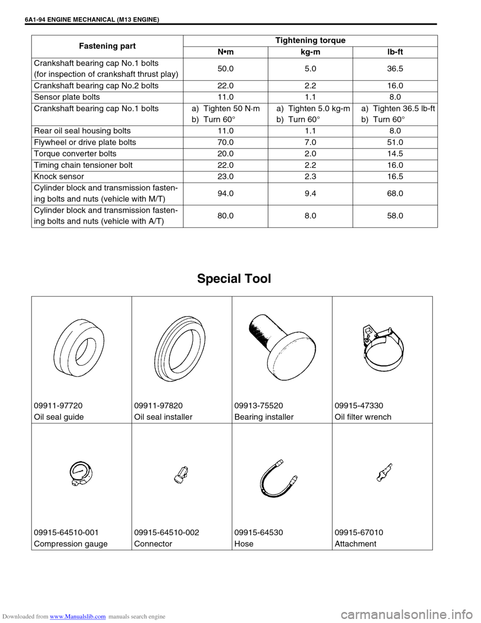
09911-97720 09911-97820 09913-75520 09915-47330
Oil seal guide Oil seal installer Bearing installer Oil filter wrench
09915-64510-001 09915-64510-002 09915-64530 09915-67010
Compression gauge Connector Hose Attachment
Page 606 of 687

Downloaded from www.Manualslib.com manuals search engine ENGINE AND EMISSION CONTROL SYSTEM 6E-1
6F1
6F2
6G
7C1
7D
7E
7A
7A1
7B1
7C1
7D
7E
7F
8A
8B
8C
8D
6H
6E
10
10A
10B
SECTION 6E
ENGINE AND EMISSION CONTROL SYSTEM
CONTENTS
General Description ....................................... 6E-3
Air Intake System ......................................... 6E-5
Fuel Delivery System ................................... 6E-6
Fuel pump ................................................ 6E-6
Electronic Control System ............................ 6E-7
Engine & emission control input / output
table.......................................................... 6E-8
On-Vehicle Service....................................... 6E-15
Accelerator cable adjustment ................. 6E-15
Idle speed / idle air control (IAC) duty
inspection ............................................... 6E-15
Idle mixture inspection / adjustment
(vehicle without heated oxygen
sensor) ................................................... 6E-17
Air Intake System ....................................... 6E-18
Throttle body .......................................... 6E-18
Idle air control valve (IAC valve)............. 6E-21
Fuel Delivery System ................................. 6E-22
Fuel pressure inspection ........................ 6E-22
Fuel pump .............................................. 6E-23
Fuel pressure regulator .......................... 6E-24
Fuel injector ............................................ 6E-25
Electronic Control System .......................... 6E-29Engine control module (ECM) ................ 6E-29
Manifold absolute pressure sensor (MAP
sensor) ................................................... 6E-29
Throttle position sensor (TP sensor) ...... 6E-30
Intake air temperature sensor
(IAT sensor) ........................................... 6E-31
Engine coolant temperature sensor
(ECT sensor) .......................................... 6E-32
Heated oxygen sensor
(Sensor-1 and sensor-2) ........................ 6E-33
Camshaft position sensor....................... 6E-34
Crankshaft position sensor..................... 6E-35
Vehicle speed sensor (VSS) .................. 6E-36
Fuel level sensor (GAUGE).................... 6E-36
Knock sensor ......................................... 6E-36
Main relay, fuel pump relay and A/C
condenser fan control relay .................... 6E-36
Fuel cut operation .................................. 6E-37
A/C condenser fan control system ......... 6E-37
A/C condenser fan ................................. 6E-37
Output signals of throttle valve opening
and engine coolant temp.
(Vehicle with A/T only) ........................... 6E-38
Emission Control System ........................... 6E-38 WARNING:
For vehicles equipped with Supplemental Restraint (Air Bag) System:
Service on and around the air bag system components or wiring must be performed only by an
authorized SUZUKI dealer. Refer to “Air Bag System Components and Wiring Location View” under
“General Description” in air bag system section in order to confirm whether you are performing ser-
vice on or near the air bag system components or wiring. Please observe all WARNINGS and “Ser-
vice Precautions” under “On-Vehicle Service” in air bag system section before performing service
on or around the air bag system components or wiring. Failure to follow WARNINGS could result in
unintentional activation of the system or could render the system inoperative. Either of these two
conditions may result in severe injury.
Technical service work must be started at least 90 seconds after the ignition switch is turned to the
“LOCK” position and the negative cable is disconnected from the battery. Otherwise, the system
may be activated by reserve energy in the Sensing and Diagnostic Module (SDM).
NOTE:
Whether following systems (parts) are used in the particular vehicle or not depends on specifications.
Be sure to bear this in mind when performing service work.
EGR valve
Heated oxygen sensor (s) or CO adjusting resistor
Three way catalytic converter (TWC) and warm up three-way catalytic converter (WU-TWC)