Page 488 of 687

Downloaded from www.Manualslib.com manuals search engine ENGINE MECHANICAL (M13 ENGINE) 6A1-7
Oil Pressure Check
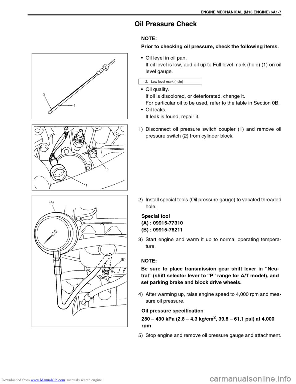
Oil level in oil pan.
If oil level is low, add oil up to Full level mark (hole) (1) on oil
level gauge.
Oil quality.
If oil is discolored, or deteriorated, change it.
For particular oil to be used, refer to the table in Section 0B.
Oil leaks.
If leak is found, repair it.
1) Disconnect oil pressure switch coupler (1) and remove oil
pressure switch (2) from cylinder block.
2) Install special tools (Oil pressure gauge) to vacated threaded
hole.
Special tool
(A) : 09915-77310
(B) : 09915-78211
3) Start engine and warm it up to normal operating tempera-
ture.
4) After warming up, raise engine speed to 4,000 rpm and mea-
sure oil pressure.
Oil pressure specification
280 – 430 kPa (2.8 – 4.3 kg/cm
2, 39.8 – 61.1 psi) at 4,000
rpm
5) Stop engine and remove oil pressure gauge and attachment.NOTE:
Prior to checking oil pressure, check the following items.
2. Low level mark (hole)
NOTE:
Be sure to place transmission gear shift lever in “Neu-
tral” (shift selector lever to “P” range for A/T model), and
set parking brake and block drive wheels.
Page 489 of 687
Downloaded from www.Manualslib.com manuals search engine 6A1-8 ENGINE MECHANICAL (M13 ENGINE)
6) Before reinstalling oil pressure switch (2), be sure to wrap its
screw threads with sealing tape (1) and tighten switch to
specified torque.
Tightening torque
Oil pressure switch (a) : 14 N.m (1.4 kg-m, 10.5 lb-ft)
7) Start engine and check oil pressure switch for oil leakage.
If oil leakage is found, repair it.
8) Connect oil pressure switch coupler (1).NOTE:
If sealing tape edge is bulged out from screw threads of
switch, cut it off.
Page 497 of 687
Downloaded from www.Manualslib.com manuals search engine 6A1-16 ENGINE MECHANICAL (M13 ENGINE)
INSTALLATION
1) Install new spark plug hole gaskets (1) and new cylinder
head cover gasket (2) to cylinder head cover (3) as shown in
figure.
2) Remove oil, old sealant, and dust from sealing surface on
cylinder head and cover. After cleaning, apply sealant “A” to
the following point.
Cylinder head gasket (1) sealing surface area (2) as shown.
“A” : Sealant 99000-31150
Timing chain cover (1) and cylinder head (2) matching sur-
face as shown.
“A” : Sealant 99000-31150 NOTE:
Be sure to check each of these parts for deterioration or
any damage before installation and replace if found
defective.
Page 512 of 687

Downloaded from www.Manualslib.com manuals search engine ENGINE MECHANICAL (M13 ENGINE) 6A1-31
INSPECTION
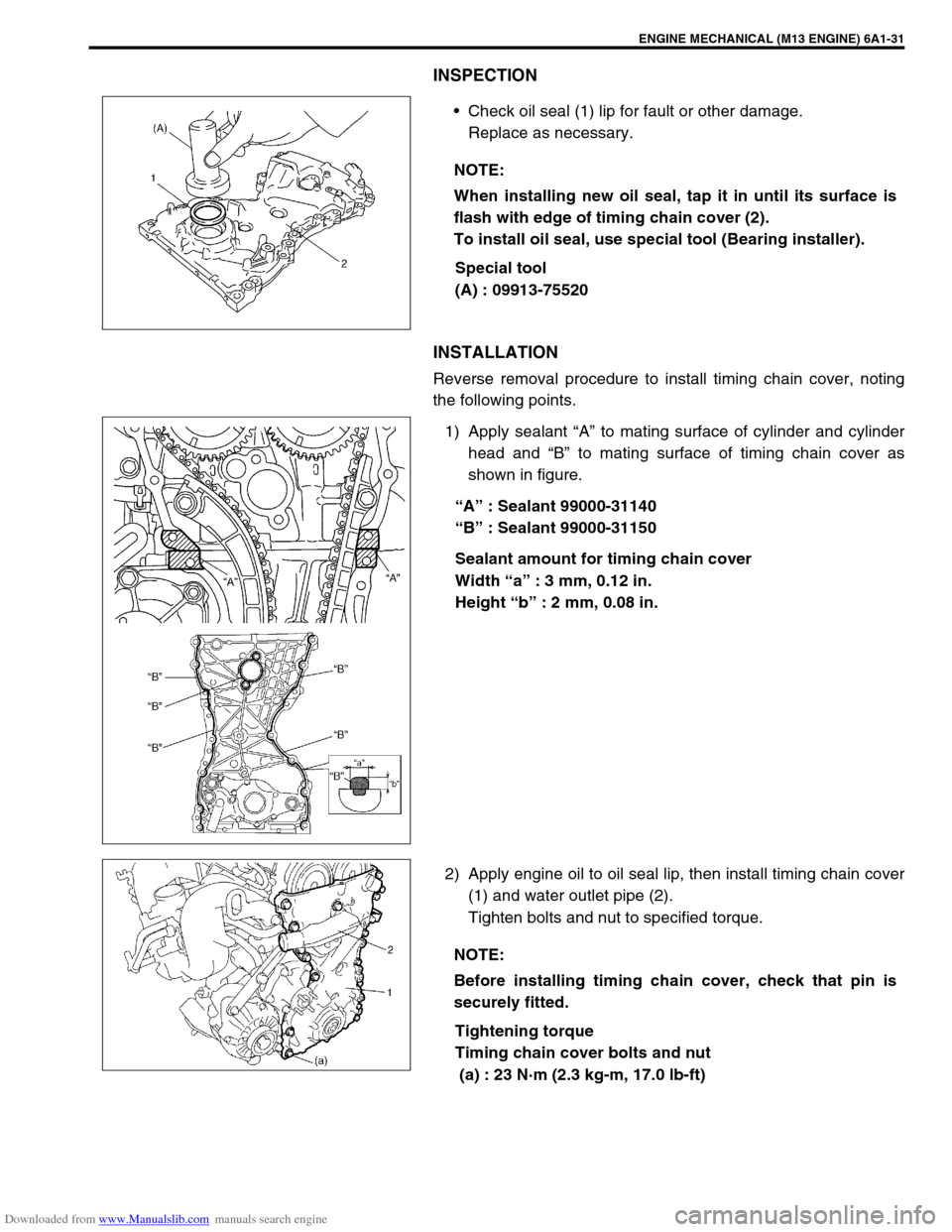
Check oil seal (1) lip for fault or other damage.
Replace as necessary.
Special tool
(A) : 09913-75520
INSTALLATION
Reverse removal procedure to install timing chain cover, noting
the following points.
1) Apply sealant “A” to mating surface of cylinder and cylinder
head and “B” to mating surface of timing chain cover as
shown in figure.
“A” : Sealant 99000-31140
“B” : Sealant 99000-31150
Sealant amount for timing chain cover
Width “a” : 3 mm, 0.12 in.
Height “b” : 2 mm, 0.08 in.
2) Apply engine oil to oil seal lip, then install timing chain cover
(1) and water outlet pipe (2).
Tighten bolts and nut to specified torque.
Tightening torque
Timing chain cover bolts and nut
(a) : 23 N·m (2.3 kg-m, 17.0 lb-ft) NOTE:
When installing new oil seal, tap it in until its surface is
flash with edge of timing chain cover (2).
To install oil seal, use special tool (Bearing installer).
NOTE:
Before installing timing chain cover, check that pin is
securely fitted.
Page 515 of 687
Downloaded from www.Manualslib.com manuals search engine 6A1-34 ENGINE MECHANICAL (M13 ENGINE)
2) Remove outer rotor (1) and inner rotor (2).
3) Remove relief valve (1), spring (2) and retainer (3) by remov-
ing circlip (4).
INSPECTION
Check oil seal lip for fault or other damage. Replace as nec-
essary.
Special tool
(A) : 09913-75520
NOTE:
When installing new oil seal (1), press-fit it till its end face
is flush with oil pump case (2) end face.
Page 516 of 687
Downloaded from www.Manualslib.com manuals search engine ENGINE MECHANICAL (M13 ENGINE) 6A1-35
Check outer (1) and inner rotors (2), rotor plate, and oil pump
case for excessive wear or damage.
Check relief valve (1) for excessive wear or damage and
operates smoothly.
MEASUREMENT
Radial clearance
Check radial clearance between outer rotor (1) and case (2),
using thickness gauge (3).
If clearance exceeds its limit, replace outer rotor or case.
Limit on radial clearance between outer rotor and case for
oil pump
0.310 mm (0.0122 in.)
Side clearance
Using straight edge (1) and thickness gauge (2), measure side
clearance.
Limit on side clearance for oil pump inner rotor
0.15 mm (0.0059 in.)
Page 517 of 687
Downloaded from www.Manualslib.com manuals search engine 6A1-36 ENGINE MECHANICAL (M13 ENGINE)
ASSEMBLY
1) Wash, clean and then dry all disassembled parts.
2) Apply thin coat of engine oil to inner and outer rotors, oil seal
lip portion, and inside surfaces of oil pump case and plate.
3) Install outer (1) and inner rotors (2) to oil pump case.
4) Install relief valve component (1) to rotor plate (2).
5) Install rotor plate and tighten all bolts to specified torque.
After installing plate, check to be sure that rotors turn
smoothly by hand (0.3 N·m (0.03 kg-m, 0.25 lb-ft) torque or
below).
Tightening torque
Oil pump rotor plate bolts (a) : 11 N·m (1.1 kg-m, 8.0 lb-ft)
INSTALLATION
For installation referring to “Timing Chain Cover” in this section.
Page 520 of 687

Downloaded from www.Manualslib.com manuals search engine ENGINE MECHANICAL (M13 ENGINE) 6A1-39
INSTALLATION
1) Check that match marks (1) on intake and exhaust camshaft
timing sprockets are in match with notches (2) on cylinder
head as shown in figure.
2) Set key (3) and turn crankshaft to position key on upside of
crankshaft.
3) Install timing chain by aligning dark blue plate (1) of timing
chain and mark (2) on camshaft timing sprocket and then
aligning dark blue plate (3) and triangle mark (4) as shown in
figure.
4) Fit crankshaft timing sprocket to timing chain by aligning gold
plate (5) of timing chain and mark (6) on crankshaft timing
sprocket. Then install crankshaft timing sprocket fitted with
chain to crankshaft.
5) Apply engine oil to sliding surface of timing chain No.1 guide
(1) and install it as shown in figure.
Tighten guide bolts to specified torque.
Tightening torque
Timing chain No.1 guide bolts
(a) : 9 N·m (0.9 kg-m, 6.5 lb-ft) CAUTION:
After timing chain is removed, never turn crankshaft and
camshafts independently more than such an extent (“a”,
“b”) as shown in figure.
If turned, interference may occur between piston and
valves and valves themselves, and parts related to piston
and valves may be damaged.
“a” :90°5. Crankshaft allowable turning range.
By key on crankshaft, within 90° from top on both right and left.
“b” :15°4. Camshaft (IN and EX) allowable turning range.
By marks on camshaft timing sprocket within 15° from notches on
cylinder head on both right and left.