Page 52 of 502
0-6RODIUS 2005.07
1491-01
CIRCUIT2) FUEL FILTER WARNING LAMP, IMMOBILIZER, SENSOR
CIRCUIT (FUEL PRESSURE, CAM SHAFT, BOOSTER
PRESSURE, CRANK SHAFT, KNOCK, COOLANT TEMP., FUEL
TEMP.)
(2) CONNECTOR IDENTIFICATION SYMBOL & PIN NUMBER POSITION (1) CONNECTOR INFORMATION
Page 156 of 502

09-10
RODIUS 2005.07
0452-01
ENGINE CONTROL SYSTEM
1) Starting Mode
When the ignition is turned ON, the ECM turns the fuel pump relay on for 1 second.
The fuel pump then builds fuel pressure.
The ECM also checks the Engine Coolant Temperature (ECT) sensor and the Throttle Position
(TP) sensor and determines the proper air/fuel ratio for starting the engine.
This ranges from1.5 to 1 at -36°C (-33°F) coolant temperature to 14.7 to 1 at 94°C
(201°F) coolant temperature.
The ECM controls the amount of fuel delivered in the starting mode by changing how long the
fuel injector is turned on and off.
This is done by ‘‘pulsing” the fuel injectors for very short times.
<007b008f008c00470099009c0095004700940096008b008c0047008f0088009a0047009b009e00960047008a00960095008b0090009b009000960095009a0047008a008800930093008c008b004702c402c400960097008c00950047009300960096009702
c9004700880095008b004702c402c4008a00930096009a008c>d loop”.
2) Run Mode
3) Open Loop
When the engine is first started and it is above 690 rpm, the system goes into “open
loop” operation. In “open loop”, the ECM ignores the signal from the O2S and calculates
the air/fuel ratio based on inputs from the ECT sensor and the MAF sensor.
The ECM stays in “open loop” until the following conditions are met:
The O2 has a varying voltage output, showing that it is hot enough to operate properly.
<007b008f008c0047006c006a007b0047009a008c0095009a0096009900470090009a0047008800890096009d008c004700880047009a0097008c008a0090008d0090008c008b0047009b008c00940097008c00990088009b009c0099008c0047004f005900
5900550047005c00b6006a00500055>
A specific amount of time has elapsed after starting the engine. -
-
-
4) Closed Loop
The specific values for the above conditions vary with different engines and are stored in the
Electronically Erasable programmable Read-Only Memory (EEPROM).
When these conditions are met, the system goes into “closed loop” operation. In “closed
loop”, the ECM calculates the air/fuel ratio (fuel injector on-time) based on the signals
from the O2 sensors.
This allows the air/fuel ratio to stay very close to 14.7 to 1.
5) Acceleration Mode
The ECM responds to rapid changes in throttle position and airflow and provides extra fuel.
The ECM responds to changes in throttle position and airflow and reduces the amount of fuel.
When deceleration is very fast, the ECM can cut off fuel completely for short periods of time.
6) Deceleration Mode
Page 164 of 502

0-3
DC 5-SPEED AUTOMATIC TRANSMISSION
RODIUS 2005.07
3650-01
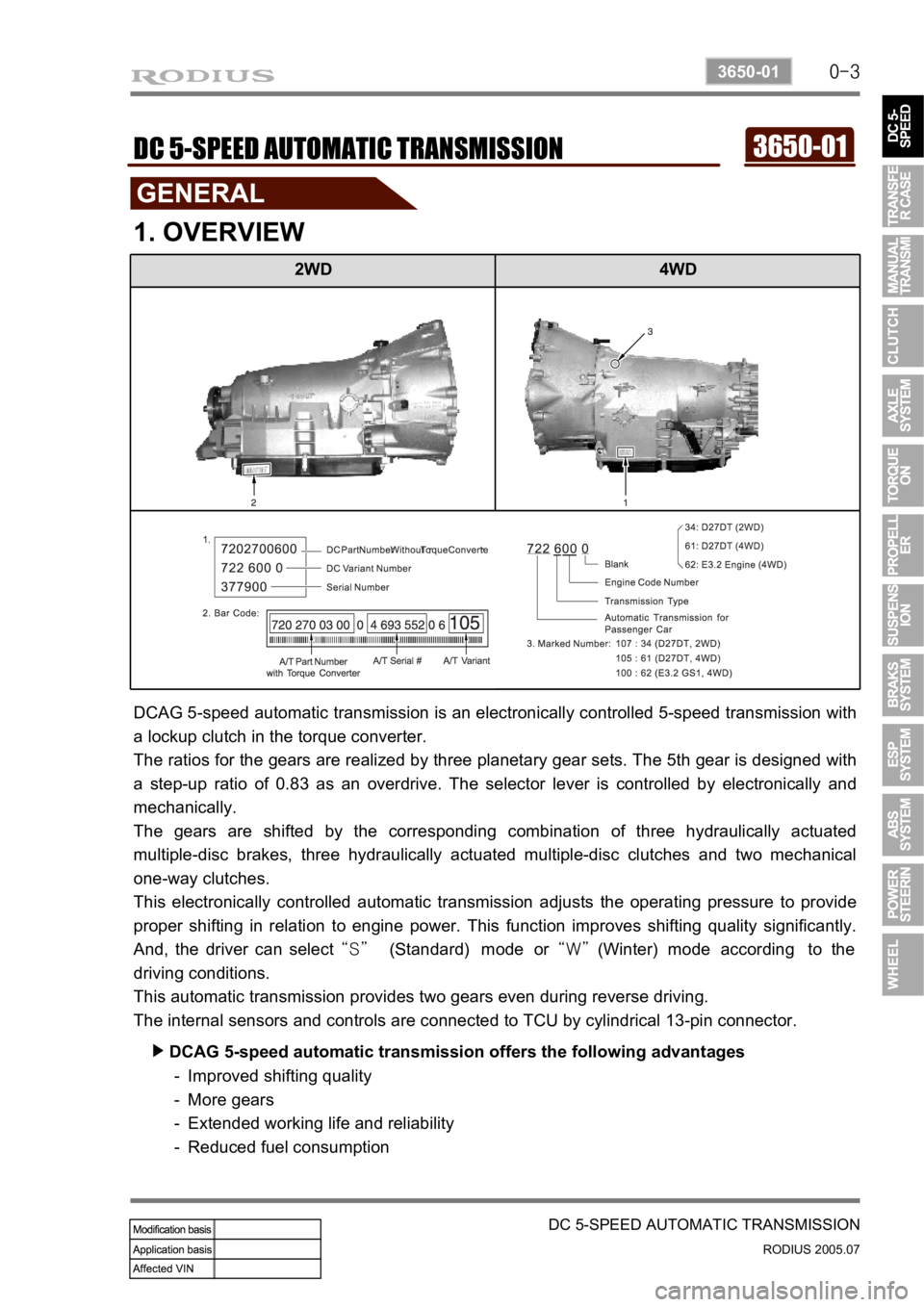
2WD 4WD
3650-01DC 5-SPEED AUTOMATIC TRANSMISSION
1. OVERVIEW
DCAG 5-speed automatic transmission is an electronically controlled 5-speed transmission with
a lockup clutch in the torque converter.
The ratios for the gears are realized by three planetary gear sets. The 5th gear is designed with
a step-up ratio of 0.83 as an overdrive. The selector lever is controlled by electronically and
mechanically.
The gears are shifted by the corresponding combination of three hydraulically actuated
multiple-disc brakes, three hydraulically actuated multiple-disc clutches and two mechanical
one-way clutches.
This electronically controlled automatic transmission adjusts the operating pressure to provide
proper shifting in relation to engine power. This function improves shifting quality significantly.
And, the driver can select “S” (Standard) mode or “W” (Winter) mode according to the
driving conditions.
This automatic transmission provides two gears even during reverse driving.
The internal sensors and controls are connected to TCU by cylindrical 13-pin connector.
DCAG 5-speed automatic transmission offers the following advantages ▶
Improved shifting quality
More gears
Extended working life and reliability
Reduced fuel consumption -
-
-
-
Page 356 of 502
0-4
RODIUS 2005.07
8010-10
CLUSTER
2. DESCRIPTIONS OF INDICATOR DISPLAY
1. Immobilizer indicator
2. Glow indicator
3. Winter mode indicator
4. Left turn signal indicator
5. Auto shift indicator (for automatic transmission)
6. Right turn signal indicator
7. Harzard indicator*
8. Engine check warning light
9. Cruise control indicator*
10. 4WD CHECK warning light
11. 4WD HIGH indicator
12. 4WD LOW indicator
13. Brake warning light14. Battery charge warning light
15. Seat belt reminder
16. Low fuel level warning light
17. Heated glass indicator
18. Door open warning light
19. High beam indicator
20. Engine oil pressure warning light
21. Air bag warning light
22. Water separator warning light
23. ABS warning light
24. EBD warning light
25. ESP warning light