2005 SSANGYONG RODIUS engine
[x] Cancel search: enginePage 201 of 502

0-4
RODIUS 2005.07
3170-01
MANUAL TRANSMISSION
1. MANUAL TRANSMISSION OVERVIEW
4WD
2WD
TSM54/52 transmission is designed to link the gear ratio, installation dimensions and shapes
with current T5 transmission and BTRA automatic transmission. It provides maximum
drivability by the optimized engine torque and gear ratio.
TSM54/52 transmission uses linkage type shift elements directly connected to the
transmission. It prevent the transmission from shifting to the reverse gear from 5th gea
r
when shifting to reverse gear. It also prevents the break and wear. 1.
2.
Page 205 of 502

0-4
RODIUS 2005.07
3010-01
CLUTCH
1. OVERVIEW
1) Driving Elements
The driving elements consist of two flat surfaces machined to a smooth finish.
One of these is the rear face of the engine flywheel and the other is the clutch cover pressure
plate. The clutch pressure plate is fitted into a clutch steel cover, which is bolted to the flywheel.
2) Driven Elements
The driven element is the clutch disc with a splined hub which is free to slide lengthwise along
the splines of the input shaft. The driving and driven elements are held in contact by spring
pressure. This pressure is exerted by a diaphragm spring in the clutch cover pressure plate
assembly.
3) Operating Elements
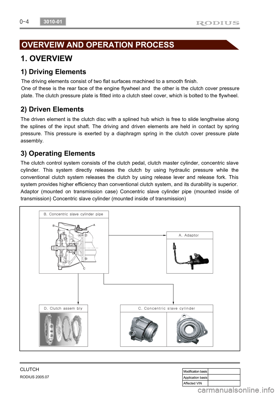
The clutch control system consists of the clutch pedal, clutch master cylinder, concentric slave
cylinder. This system directly releases the clutch by using hydraulic pressure while the
conventional clutch system releases the clutch by using release lever and release fork. This
system provides higher efficiency than conventional clutch system, and its durability is superior.
Adaptor (mounted on transmission case) Concentric slave cylinder pipe (mounted inside o
f
transmission) Concentric slave cylinder (mounted inside of transmission)
Page 206 of 502

0-5
CLUTCH
RODIUS 2005.07
3010-01
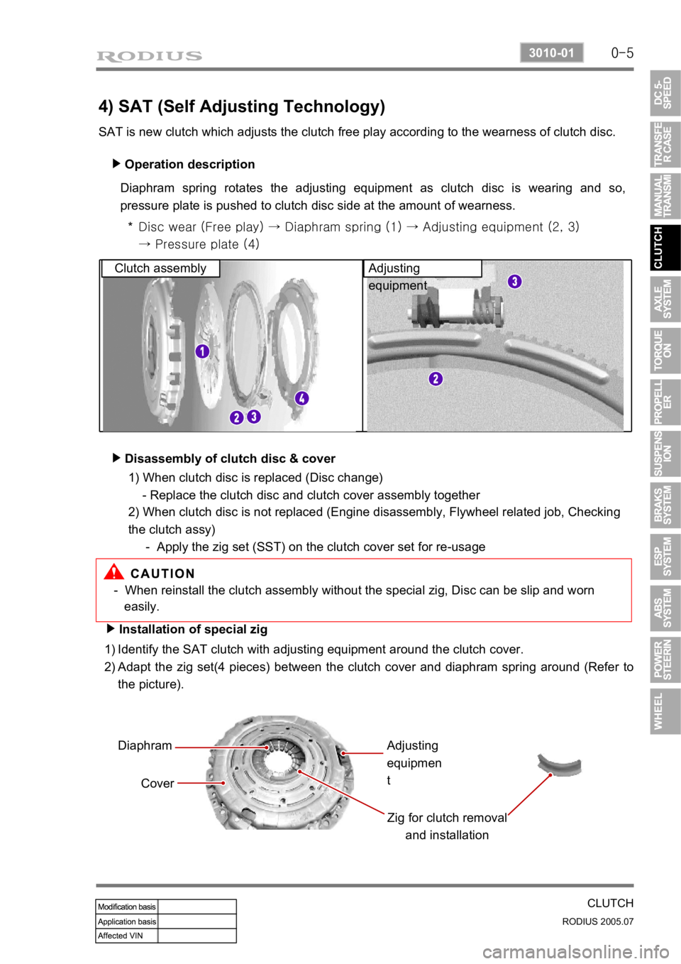
4) SAT (Self Adjusting Technology)
SAT is new clutch which adjusts the clutch free play according to the wearness of clutch disc. Operation description
▶
Diaphram spring rotates the adjusting equipment as clutch disc is wearing and so,
pressure plate is pushed to clutch disc side at the amount of wearness.
Disc wear (Free play) → Diaphram spring (1) → Adjusting equipme nt (2, 3)
→ Pressure plate (4)
*
Clutch assembly Adjusting
equipment
Disassembly of clutch disc & cover
▶
- When reinstall the clutch assembly without the special zig, Disc can be slip and worn
easily.
Installation of special zig
▶
Identify the SAT clutch with adjusting equipment around the clutch cover.
Adapt the zig set(4 pieces) between the clutch cover and diaphram spring around (Refer to
the picture).
1)
2)
Diaphram
Cover Zig for clutch removal and installationAdjusting
equipmen
t
1) When clutch disc is replaced (Disc change)
- Replace the clutch disc and clutch cover assembly together
2) When clutch disc is not replaced (Engine disassembly, Flywheel related job, Checking
the clutch assy)
- Apply the zig set (SST) on the clutch cover set for re-usage
Page 212 of 502

0-5
TORQUE ON DEMAND
RODIUS 2005.07
3240-01
2. GENERAL DESCRIPTION
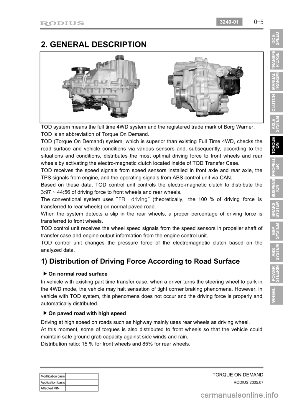
TOD system means the full time 4WD system and the registered trade mark of Borg Warner.
TOD is an abbreviation of Torque On Demand.
TOD (Torque On Demand) system, which is superior than existing Full Time 4WD, checks the
road surface and vehicle conditions via various sensors and, subsequently, according to the
situations and conditions, distributes the most optimal driving force to front wheels and rea
r
wheels by activating the electro-magnetic clutch located inside of TOD Transfer Case.
TOD receives the speed signals from speed sensors installed in front axle and rear axle, the
TPS signals from engine, and the operating signals from ABS control unit via CAN.
Based on these data, TOD control unit controls the electro-magnetic clutch to distribute the
3:97 ~ 44:56 of driving force to front wheels and rear wheels.
The conventional system uses “FR driving” (theoretically, the 100 % of driving force is
transferred to rear wheels) on normal paved road.
When the system detects a slip in the rear wheels, a proper percentage of driving force is
transferred to front wheels.
TOD control unit receives the wheel speed signals from the speed sensors in propeller shaft o
f
transfer case and engine output information from the engine control unit.
TOD control unit changes the pressure force of the electromagnetic clutch based on the
analyzed data.
1) Distribution of Driving Force According to Road Surface
On normal road surface ▶
In vehicle with existing part time transfer case, when a driver turns the steering wheel to park in
the 4WD mode, the vehicle may halt sensation of tight corner braking phenomena. However, in
vehicle with TOD system, this phenomena does not occur and the driving force is properly and
automatically distributed.
On paved road with high speed ▶
Driving at high speed on roads such as highway mainly uses rear wheels as driving wheel.
At this moment, some of torques is also distributed to front wheels so that the vehicle could
maintain safe ground grab capacity against side winds and rain.
Distribution ratio: 15 % for front wheels and 85% for rear wheels.
Page 237 of 502

0-4
RODIUS 2005.07
4892-01
ESP SYSTEM
1. COMPONENTS AND LOCATIONS
2WD vehicle has the longitudinal sensor in the HECU.
1. HECU: (Hydraulic &
Engine conrol unit) 2. Pressure sensor 3. Wheel speed sensor
4. Sensor cluster:
(Yaw rate + lateral sensor + longitudinal sensor) 5. Steering wheel angle
sensor 6. ESP off switch (Electronic
Stability Program Switch) ESP Warning lamp
Page 239 of 502

0-6
RODIUS 2005.07
4892-01
ESP SYSTEM
3. ESP SYSTEM DESCRIPTION
1) Principle of ESP
ESP (Electronic Stability Program) recognizes critical driving conditions, such as panic
reactions in dangerous situations, and stabilizes the vehicle by wheel-individual braking and
engine control intervention with no need for actuating the brake. This system is developed to
help the driver avoid the danger of losing the control of the vehicle stability due to under-
steering or over-steering during cornering.
The yaw rate sensor, lateral sensor and longitudinal sensor in the sensor cluster and the
steering wheel angle sensor under the steering column detect the spin present at any wheels
during over-steering, under-steering or cornering. The ESP ECU controls against over-steering
or under-steering during cornering by controlling the vehicle stability using the input values from
the sensors and applying the brakes independently to the corresponding wheels.
The system also controls during cornering by detecting the moment right before the spin and
automatically limiting the engine output (coupled with the ASR system).
Understeering is when the steering wheel is
steered to a certain angle during driving and
the front tires slip toward the reverse
direction of the desired direction. Generally,
vehicles are designed to have unde
r
steering. The vehicle can return back to
inside of cornering line when the steering
wheel is steered toward the inside even
when the vehicle front is slipped outward.
As
the centrifugal force increases, the tires can
easily lose the traction and the vehicle tends
to slip outward when the curve angle gets
bigger and the speed increases. Under steering
ESP controls during under steering
The ESP system recognizes the directional
angle with the steering wheel angle senso
r
and senses the slipping route that occurs
reversely against the vehicle cornering
direction during understeering with the yaw
rate sensor and the lateral sensor. Then the
ESP system applies the brake at the rea
r
inner wheel to compensate the yaw moment
value.
In this way, the vehicle does not lose its
driving direction and the driver can steer the
vehicle as driver intends.
Page 247 of 502

0-14
RODIUS 2005.07
4892-01
ESP SYSTEM
(1) System Overview
When equipped with ABS, the braking force at each wheel will be controlled with 3-channel 4-
sensor method. And when equipped with ESP, 4 wheels will be controlled independently with 4-
channel method. (When controlling ABS system only, it will be operated with 3-channel
method.) When compared to the vehicle equipped with ABS/EBD only, the internal hydraulic
circuit has a normally-open separation valve and a shuttle valve in primary circuit and in
secondary circuit. When the vehicle brakes are not applied during engine running or when
applying the non-ABS operating brakes, the normally-open separation valve and the inlet valve
are open, whereas the normally-closed shuttle valve and the outlet valve are closed. When the
ESP system is operating, the normally-open separation valve will be closed by the solenoid
valve operation and the hydraulic circuit will be established by the shuttle valve. Then, the inlet
and outlet valves will be
closed or open depending on the braking pressure increase, decrease or unchanged
conditions.
<0d96007b008f008c0047009e00880099009500900095008e004700930088009400970047008a00960094008c009a004700960095004700880095008b0047009e00880099009500900095008e00470089008c008c00970047009a0096009c0095008b009a00
47009e008f008c00950047009b008f008c0047006c007a0077> is operating
▶Driving feeling when the ESP is operating
<0d96007500960090009a008c004700880095008b0047009d0090008900990088009b0090009600950047009b008f0088009b0047008b00990090009d008c00990047009a008c0095009a008c009a0047009e008f008c00950047009b008f008c0047006c00
7a007700470090009a004700960097008c00990088009b0090>ng When the ESP operates during vehicle movement, the ESP warning lamp on the instrument
panel flickers and beep comes on every 0.1 seconds. The ESP operation shows that the
vehicle stability is extremely unstable and it is used to warn the driver. The ESP system is just a
supplementary system for the vehicle motion and it cannot control the vehicle when it exceeds
the physical limits. Do not solely rely on the system but be advised to drive the vehicle safely.
When the ESP system activates, the driving feeling can be different depending on vehicle
driving conditions. For example, you will feel differently when the ESP system is activated
during when ABS is operating with the brakes applied and when brakes are not applied on a
curve. Thus, the ESP system would make the driver feel more abruptly when the brakes are
applied during the ESP system activation.
The ESP system may transfer noise and vibration to the driver due to the pressure changes
caused by the motor and valve operations in a very short period of time. Extreme cornering will
trigger the ESP operation and this will make the driver feel noise and vibration due to sudden
brake application. Also, the ESP system controls the engine output. So, the driver may notice
the engine output decrease even when the accelerator pedal is being applied.
Page 265 of 502

0-13
ABS SYSTEM
RODIUS 2005.07
4892-01
1) System Fuse
2) Indicators
The ABS/TCS system fuse and SB2 is
located at the fuse box in engine
compartment.
The ABS and TCS indicators are in
instrument cluster.