Page 3234 of 4555
ATC-56
TROUBLE DIAGNOSIS
20 L/W Power supply for IGN2 ON - Battery voltage
21 GY Water temperature sensor ONAt idle [after warming up,
approx. 80°C (176°F)]
CAUTION:
The waveforms vary depend-
ing on coolant temperature
22 LG/BRear window defogger ON
signalONRear window defogger: ON Approx. 0
Rear window defogger: OFF Approx. 12
23 B/WRear window defogger feed
back signalONRear window defogger: ON Approx. 12
Rear window defogger: OFF Approx. 0
24 B/Y Sensor ground ON - Approx. 0
25 BR/Y Intake sensor - - -
28 YPower supply for ambient
temperature displayON - Approx. 5
30 PU Compressor feed back signal ON-Approx. 0
When refrigerant pressure sen-
sor connector is disconnectedApprox. 5 Te r m i -
nal No.Wire
colorItemIgnition
switchConditionVoltage
(V)
SKIA0056J
Page 3266 of 4555
ATC-88
TROUBLE DIAGNOSIS
Magnet Clutch CircuitEJS004YO
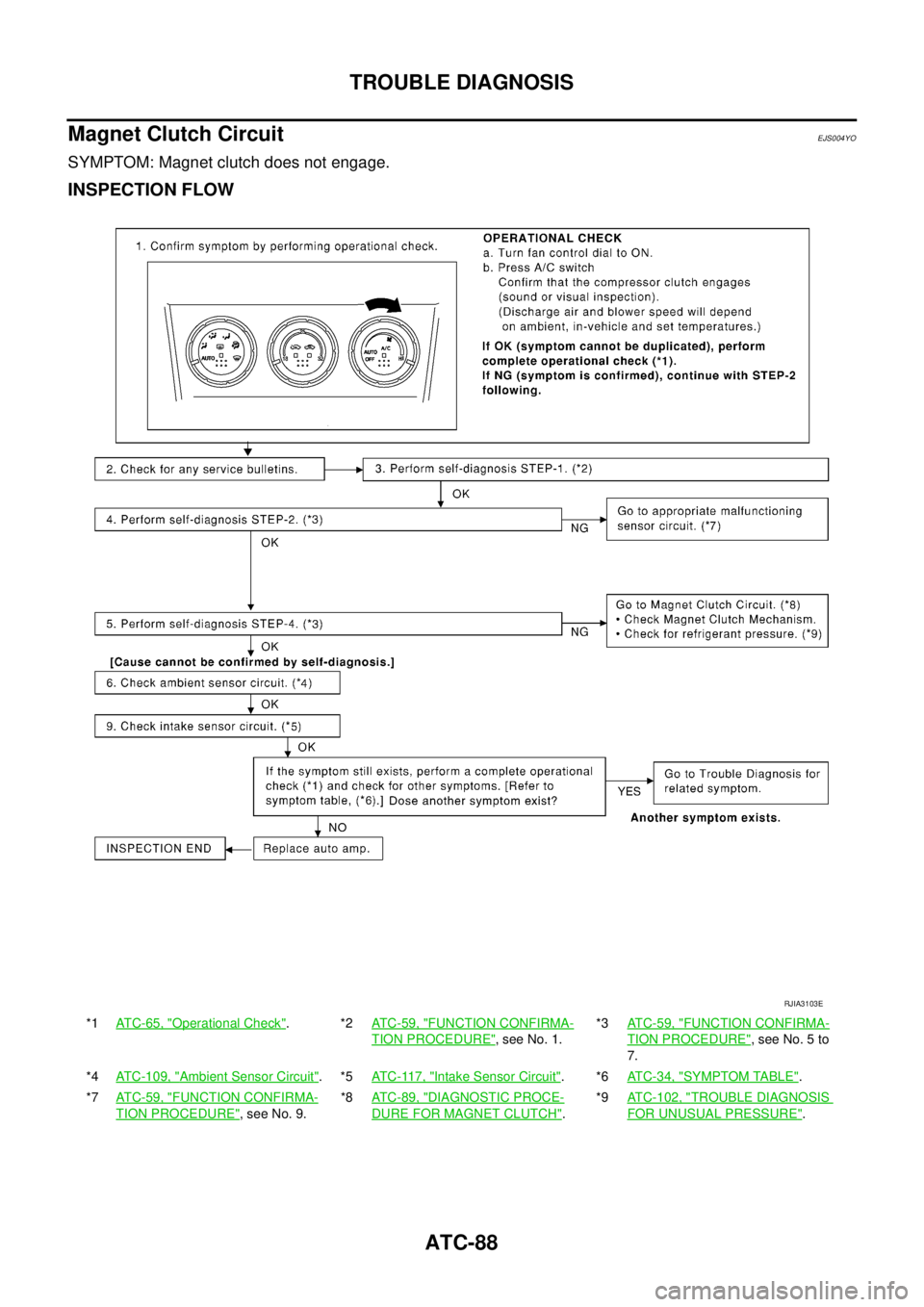
SYMPTOM: Magnet clutch does not engage.
INSPECTION FLOW
*1AT C - 6 5 , "Operational Check".*2ATC-59, "FUNCTION CONFIRMA-
TION PROCEDURE", see No. 1.*3ATC-59, "
FUNCTION CONFIRMA-
TION PROCEDURE", see No. 5 to
7.
*4ATC-109, "
Ambient Sensor Circuit".*5ATC-117, "Intake Sensor Circuit".*6ATC-34, "SYMPTOM TABLE".
*7AT C - 5 9 , "
FUNCTION CONFIRMA-
TION PROCEDURE", see No. 9.*8ATC-89, "
DIAGNOSTIC PROCE-
DURE FOR MAGNET CLUTCH".*9ATC-102, "
TROUBLE DIAGNOSIS
FOR UNUSUAL PRESSURE".
RJIA3103E
Page 3269 of 4555
TROUBLE DIAGNOSIS
ATC-91
C
D
E
F
G
H
I
K
L
MA
B
AT C
4. CHECK POWER SUPPLY FOR A/C RELAY
1. Turn ignition switch ON.
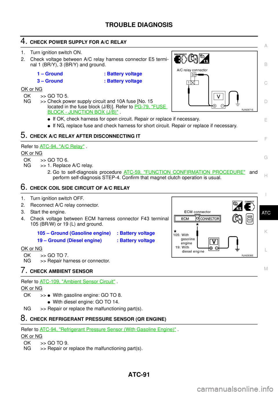
2. Check voltage between A/C relay harness connector E5 termi-
nal 1 (BR/Y), 3 (BR/Y) and ground.
OK or NG
OK >> GO TO 5.
NG >> Check power supply circuit and 10A fuse [No. 15
located in the fuse block (J/B)]. Refer to PG-79, "
FUSE
BLOCK - JUNCTION BOX (J/B)" .
�If OK, check harness for open circuit. Repair or replace if necessary.
�If NG, replace fuse and check harness for short circuit. Repair or replace if necessary.
5. CHECK A/C RELAY AFTER DISCONNECTING IT
Refer to AT C - 9 4 , "
A/C Relay" .
OK or NG
OK >> GO TO 6.
NG >> 1. Replace A/C relay.
2. Go to self-diagnosis procedure AT C - 5 9 , "
FUNCTION CONFIRMATION PROCEDURE" and
perform self-diagnosis STEP-4. Confirm that magnet clutch operation is usual.
6. CHECK COIL SIDE CIRCUIT OF A/C RELAY
1. Turn ignition switch OFF.
2. Reconnect A/C relay connector.
3. Start the engine.
4. Check voltage between ECM harness connector F43 terminal
105 (BR/W) or 19 (L) and ground.
OK or NG
OK >> GO TO 7.
NG >> Repair harness or connector.
7. CHECK AMBIENT SENSOR
Refer to ATC-109, "
Ambient Sensor Circuit" .
OK or NG
OK >>�With gasoline engine: GO TO 8.
�With diesel engine: GO TO 14.
NG >> Repair or replace the malfunctioning part(s).
8. CHECK REFRIGERANT PRESSURE SENSOR (QR ENGINE)
Refer to AT C - 9 4 , "
Refrigerant Pressure Sensor (With Gasoline Engine)" .
OK or NG
OK >> GO TO 9.
NG >> Repair or replace the malfunctioning part(s).1 – Ground : Battery voltage
3 – Ground : Battery voltage
RJIA2871E
105 – Ground (Gasoline engine) : Battery voltage
19 – Ground (Diesel engine) : Battery voltage
RJIA2836E
Page 3272 of 4555
ATC-94
TROUBLE DIAGNOSIS
16. CHECK CIRCUIT CONTINUITY BETWEEN DUAL-PRESSURE SWITCH AND COMBINATION
METER
1. Disconnect the combination meter connector.
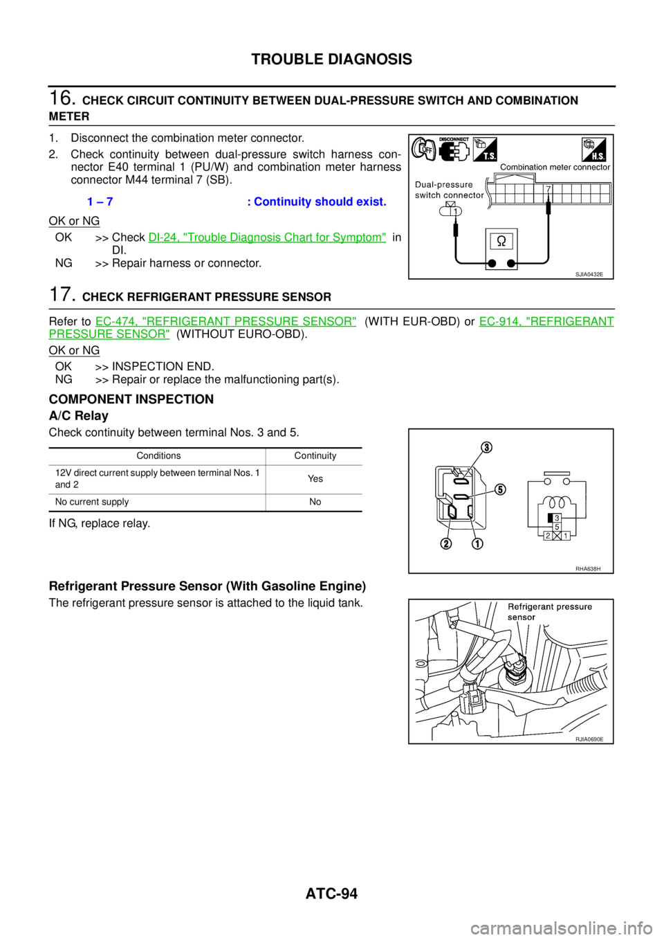
2. Check continuity between dual-pressure switch harness con-
nector E40 terminal 1 (PU/W) and combination meter harness
connector M44 terminal 7 (SB).
OK or NG
OK >> Check DI-24, "Trouble Diagnosis Chart for Symptom" in
DI.
NG >> Repair harness or connector.
17. CHECK REFRIGERANT PRESSURE SENSOR
Refer to EC-474, "
REFRIGERANT PRESSURE SENSOR" (WITH EUR-OBD) or EC-914, "REFRIGERANT
PRESSURE SENSOR" (WITHOUT EURO-OBD).
OK or NG
OK >> INSPECTION END.
NG >> Repair or replace the malfunctioning part(s).
COMPONENT INSPECTION
A/C Relay
Check continuity between terminal Nos. 3 and 5.
If NG, replace relay.
Refrigerant Pressure Sensor (With Gasoline Engine)
The refrigerant pressure sensor is attached to the liquid tank.1 – 7 : Continuity should exist.
SJIA0432E
Conditions Continuity
12V direct current supply between terminal Nos. 1
and 2Ye s
No current supply No
RHA638H
RJIA0690E
Page 3281 of 4555
TROUBLE DIAGNOSIS
ATC-103
C
D
E
F
G
H
I
K
L
MA
B
AT C
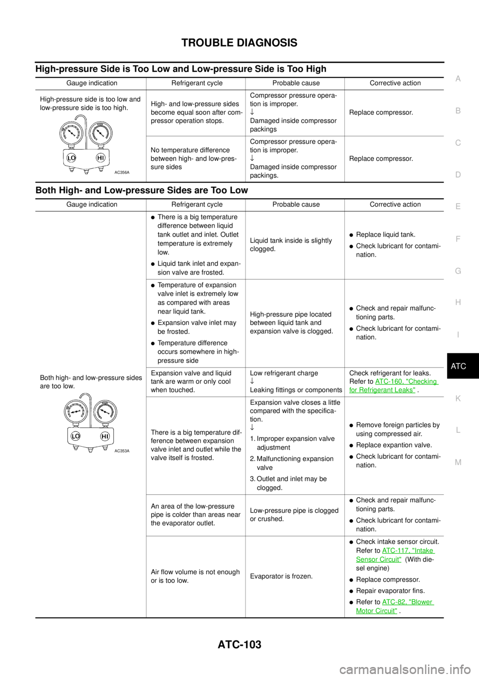
High-pressure Side is Too Low and Low-pressure Side is Too High
Both High- and Low-pressure Sides are Too Low
Gauge indication Refrigerant cycle Probable cause Corrective action
High-pressure side is too low and
low-pressure side is too high.High- and low-pressure sides
become equal soon after com-
pressor operation stops.Compressor pressure opera-
tion is improper.
↓
Damaged inside compressor
packingsReplace compressor.
No temperature difference
between high- and low-pres-
sure sidesCompressor pressure opera-
tion is improper.
↓
Damaged inside compressor
packings.Replace compressor.
AC356A
Gauge indication Refrigerant cycle Probable cause Corrective action
Both high- and low-pressure sides
are too low.
�There is a big temperature
difference between liquid
tank outlet and inlet. Outlet
temperature is extremely
low.
�Liquid tank inlet and expan-
sion valve are frosted.Liquid tank inside is slightly
clogged.
�Replace liquid tank.
�Check lubricant for contami-
nation.
�Temperature of expansion
valve inlet is extremely low
as compared with areas
near liquid tank.
�Expansion valve inlet may
be frosted.
�Temperature difference
occurs somewhere in high-
pressure sideHigh-pressure pipe located
between liquid tank and
expansion valve is clogged.
�Check and repair malfunc-
tioning parts.
�Check lubricant for contami-
nation.
Expansion valve and liquid
tank are warm or only cool
when touched.Low refrigerant charge
↓
Leaking fittings or componentsCheck refrigerant for leaks.
Refer to ATC-160, "
Checking
for Refrigerant Leaks" .
There is a big temperature dif-
ference between expansion
valve inlet and outlet while the
valve itself is frosted.Expansion valve closes a little
compared with the specifica-
tion.
↓
1. Improper expansion valve
adjustment
2. Malfunctioning expansion
valve
3. Outlet and inlet may be
clogged.
�Remove foreign particles by
using compressed air.
�Replace expantion valve.
�Check lubricant for contami-
nation.
An area of the low-pressure
pipe is colder than areas near
the evaporator outlet.Low-pressure pipe is clogged
or crushed.
�Check and repair malfunc-
tioning parts.
�Check lubricant for contami-
nation.
Air flow volume is not enough
or is too low.Evaporator is frozen.
�Check intake sensor circuit.
Refer to AT C - 11 7 , "
Intake
Sensor Circuit" (With die-
sel engine)
�Replace compressor.
�Repair evaporator fins.
�Refer to AT C - 8 2 , "Blower
Motor Circuit" .
AC353A
Page 3289 of 4555
TROUBLE DIAGNOSIS
ATC-111
C
D
E
F
G
H
I
K
L
MA
B
AT C
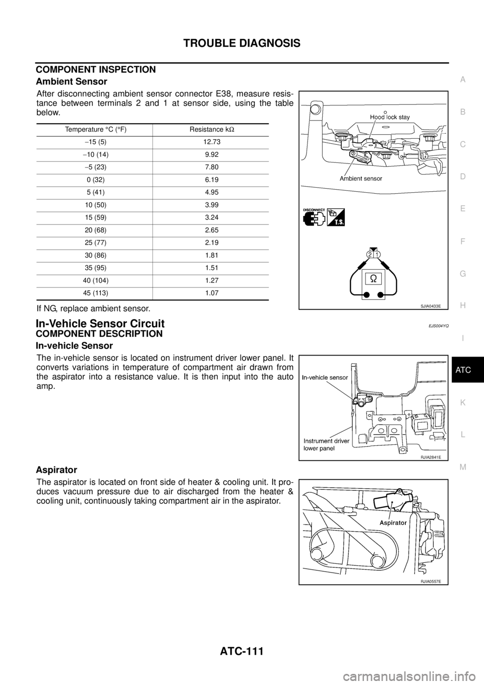
COMPONENT INSPECTION
Ambient Sensor
After disconnecting ambient sensor connector E38, measure resis-
tance between terminals 2 and 1 at sensor side, using the table
below.
If NG, replace ambient sensor.
In-Vehicle Sensor CircuitEJS004YQ
COMPONENT DESCRIPTION
In-vehicle Sensor
The in-vehicle sensor is located on instrument driver lower panel. It
converts variations in temperature of compartment air drawn from
the aspirator into a resistance value. It is then input into the auto
amp.
Aspirator
The aspirator is located on front side of heater & cooling unit. It pro-
duces vacuum pressure due to air discharged from the heater &
cooling unit, continuously taking compartment air in the aspirator.
Temperature °C (°F) Resistance kΩ
−15 (5) 12.73
−10 (14) 9.92
−5 (23) 7.80
0 (32) 6.19
5 (41) 4.95
10 (50) 3.99
15 (59) 3.24
20 (68) 2.65
25 (77) 2.19
30 (86) 1.81
35 (95) 1.51
40 (104) 1.27
45 (113) 1.07
SJIA0433E
RJIA2841E
RJIA0557E
Page 3334 of 4555
ATC-156
REFRIGERANT LINES
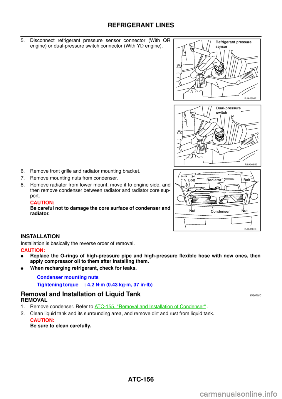
5. Disconnect refrigerant pressure sensor connector (With QR
engine) or dual-pressure switch connector (With YD engine).
6. Remove front grille and radiator mounting bracket.
7. Remove mounting nuts from condenser.
8. Remove radiator from lower mount, move it to engine side, and
then remove condenser between radiator and radiator core sup-
port.
CAUTION:
Be careful not to damage the core surface of condenser and
radiator.
INSTALLATION
Installation is basically the reverse order of removal.
CAUTION:
�Replace the O-rings of high-pressure pipe and high-pressure flexible hose with new ones, then
apply compressor oil to them after installing them.
�When recharging refrigerant, check for leaks.
Removal and Installation of Liquid TankEJS0028C
REMOVAL
1. Remove condenser. Refer to ATC-155, "Removal and Installation of Condenser" .
2. Clean liquid tank and its surrounding area, and remove dirt and rust from liquid tank.
CAUTION:
Be sure to clean carefully.
RJIA0690E
RJIA0691E
RJIA0081E
Condenser mounting nuts
Tightening torque : 4.2 N·m (0.43 kg-m, 37 in-lb)
Page 3335 of 4555
REFRIGERANT LINES
ATC-157
C
D
E
F
G
H
I
K
L
MA
B
AT C
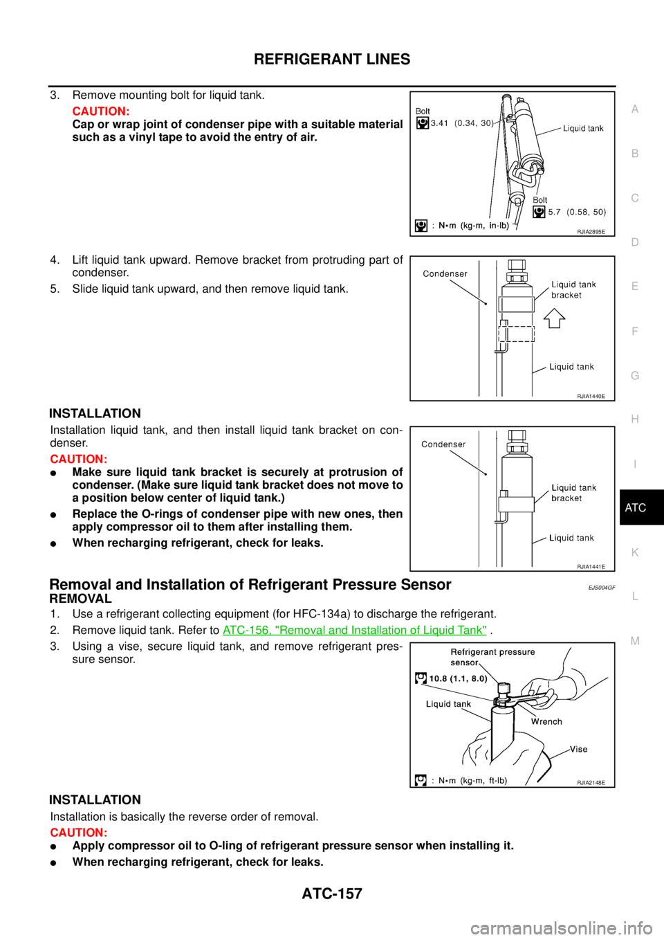
3. Remove mounting bolt for liquid tank.
CAUTION:
Cap or wrap joint of condenser pipe with a suitable material
such as a vinyl tape to avoid the entry of air.
4. Lift liquid tank upward. Remove bracket from protruding part of
condenser.
5. Slide liquid tank upward, and then remove liquid tank.
INSTALLATION
Installation liquid tank, and then install liquid tank bracket on con-
denser.
CAUTION:
�Make sure liquid tank bracket is securely at protrusion of
condenser. (Make sure liquid tank bracket does not move to
a position below center of liquid tank.)
�Replace the O-rings of condenser pipe with new ones, then
apply compressor oil to them after installing them.
�When recharging refrigerant, check for leaks.
Removal and Installation of Refrigerant Pressure SensorEJS004GF
REMOVAL
1. Use a refrigerant collecting equipment (for HFC-134a) to discharge the refrigerant.
2. Remove liquid tank. Refer to ATC-156, "
Removal and Installation of Liquid Tank" .
3. Using a vise, secure liquid tank, and remove refrigerant pres-
sure sensor.
INSTALLATION
Installation is basically the reverse order of removal.
CAUTION:
�Apply compressor oil to O-ling of refrigerant pressure sensor when installing it.
�When recharging refrigerant, check for leaks.
RJIA2895E
RJIA1440E
RJIA1441E
RJIA2148E
![NISSAN X-TRAIL 2005 Service Repair Manual ATC-56
TROUBLE DIAGNOSIS
20 L/W Power supply for IGN2 ON - Battery voltage
21 GY Water temperature sensor ONAt idle [after warming up,
approx. 80°C (176°F)]
CAUTION:
The waveforms vary depend-
in](/manual-img/5/57403/w960_57403-3233.png "NISSAN X-TRAIL 2005 Service Repair Manual ATC-56
TROUBLE DIAGNOSIS
20 L/W Power supply for IGN2 ON - Battery voltage
21 GY Water temperature sensor ONAt idle [after warming up,
approx. 80°C (176°F)]
CAUTION:
The waveforms vary depend-
in")