Page 377 of 4555
![NISSAN X-TRAIL 2005 Service Repair Manual WATER PUMP
CO-21
[QR]
C
D
E
F
G
H
I
J
K
L
MA
CO
WAT E R P U MPPFP:21020
Removal and InstallationEBS00KON
REMOVAL
1. Drain engine coolant. Refer to CO-9, "Changing Engine Coolant" .
CAUTION:
�Perfor](/manual-img/5/57403/w960_57403-376.png "NISSAN X-TRAIL 2005 Service Repair Manual WATER PUMP
CO-21
[QR]
C
D
E
F
G
H
I
J
K
L
MA
CO
WAT E R P U MPPFP:21020
Removal and InstallationEBS00KON
REMOVAL
1. Drain engine coolant. Refer to CO-9, \"Changing Engine Coolant\" .
CAUTION:
�Perfor")
WATER PUMP
CO-21
[QR]
C
D
E
F
G
H
I
J
K
L
MA
CO
WAT E R P U MPPFP:21020
Removal and InstallationEBS00KON
REMOVAL
1. Drain engine coolant. Refer to CO-9, "Changing Engine Coolant" .
CAUTION:
�Perform this step when engine is cold.
�Do not spill engine coolant on drive belt.
2. Remove the following parts.
�RH undercover
�Drive belt; Refer to EM-13, "DRIVE BELTS" .
�Drive belt auto-tensioner; Refer to EM-14, "Removal and Installation of Drive Belt Auto-Tensioner" .
3. Remove water pump.
�Engine coolant will leak from cylinder block, so have a receptacle ready below.
CAUTION:
�Handle water pump vane so that it does not contact any other parts.
�Water pump cannot be disassembled and should be replaced as a unit.
4. Remove water pump housing with the following procedure;
a. Remove alternator. Refer to SC-13, "
CHARGING SYSTEM" .
b. Remove oil level gauge and oil level gauge guide. Refer to EM-27, "
OIL PAN AND OIL STRAINER" .
CAUTION:
Plug the oil level gauge guide opening to prevent oil pan from entering foreign materials.
c. Remove mounting bolts for water pipe.
d. Remove water pump housing.
5. Remove exhaust manifold and three way catalyst assembly. Refer to EM-25, "
EXHAUST MANIFOLD
AND THREE WAY CATALYST" .
6. Remove water pipe.
1. Water pump 2. Gasket 3. Gasket
4. Water pump housing 5. Gasket 6. Water pipe
7. O-ring
PBIC2253E
Page 378 of 4555
CO-22
[QR]
WATER PUMP
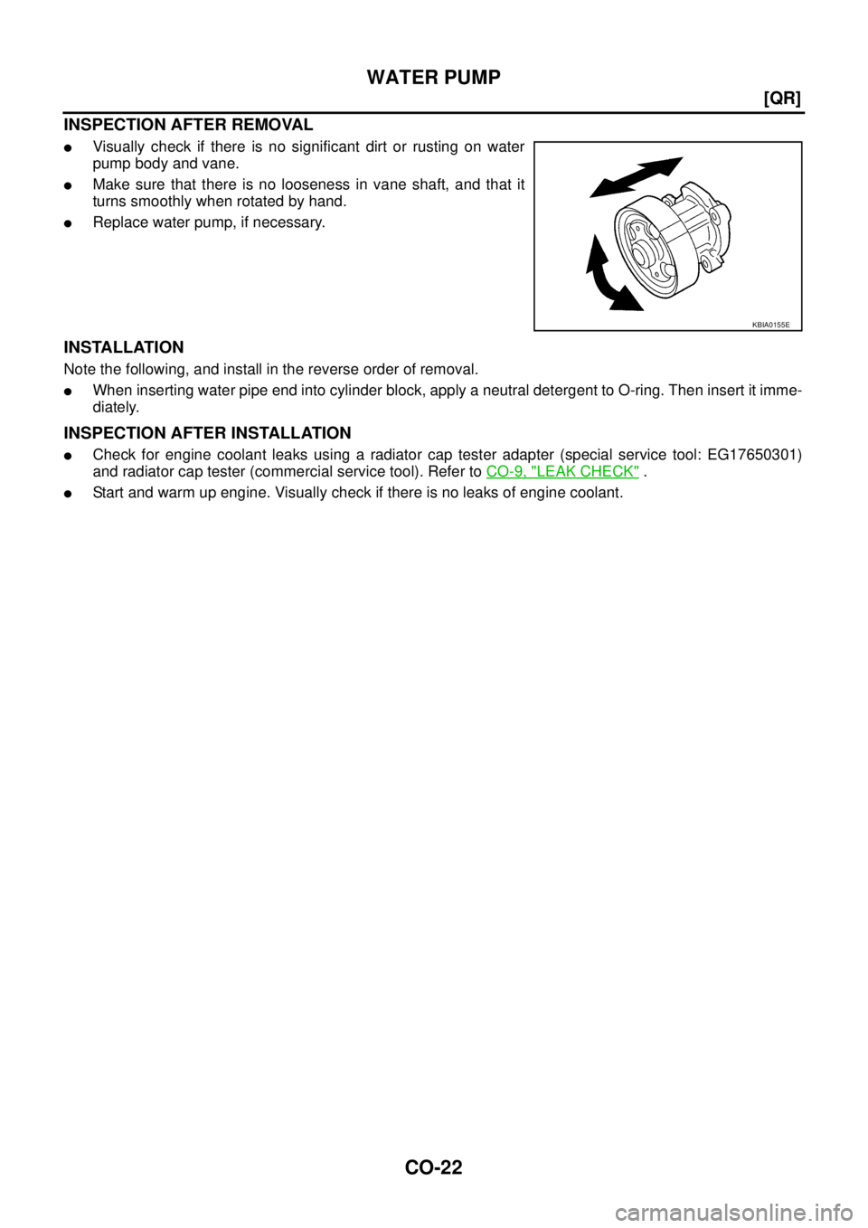
INSPECTION AFTER REMOVAL
�Visually check if there is no significant dirt or rusting on water
pump body and vane.
�Make sure that there is no looseness in vane shaft, and that it
turns smoothly when rotated by hand.
�Replace water pump, if necessary.
INSTALLATION
Note the following, and install in the reverse order of removal.
�When inserting water pipe end into cylinder block, apply a neutral detergent to O-ring. Then insert it imme-
diately.
INSPECTION AFTER INSTALLATION
�Check for engine coolant leaks using a radiator cap tester adapter (special service tool: EG17650301)
and radiator cap tester (commercial service tool). Refer to CO-9, "
LEAK CHECK" .
�Start and warm up engine. Visually check if there is no leaks of engine coolant.
KBIA0155E
Page 381 of 4555
![NISSAN X-TRAIL 2005 Service Repair Manual SERVICE DATA AND SPECIFICATIONS (SDS)
CO-25
[QR]
C
D
E
F
G
H
I
J
K
L
MA
CO
SERVICE DATA AND SPECIFICATIONS (SDS)PFP:00030
Standard and LimitEBS00KOP
CAPACITY
Unit: (lmp qt)
RADIATOR
Unit: kPa (bar](/manual-img/5/57403/w960_57403-380.png "NISSAN X-TRAIL 2005 Service Repair Manual SERVICE DATA AND SPECIFICATIONS (SDS)
CO-25
[QR]
C
D
E
F
G
H
I
J
K
L
MA
CO
SERVICE DATA AND SPECIFICATIONS (SDS)PFP:00030
Standard and LimitEBS00KOP
CAPACITY
Unit: (lmp qt)
RADIATOR
Unit: kPa (bar")
SERVICE DATA AND SPECIFICATIONS (SDS)
CO-25
[QR]
C
D
E
F
G
H
I
J
K
L
MA
CO
SERVICE DATA AND SPECIFICATIONS (SDS)PFP:00030
Standard and LimitEBS00KOP
CAPACITY
Unit: (lmp qt)
RADIATOR
Unit: kPa (bar, kg/cm2 , psi)
THERMOSTAT
WATER CONTROL VALVE
*: Reference data
Tightening TorqueEBS00KOQ
Unit: N·m (kg-m, ft-lb)
Unit: N·m (kg-m, in-lb)*
Engine coolant capacity (With reservoir tank at “MAX” level) Approx. 7.1 (6-1/4)
Reservoir tank0.7 (5/8)
Cap relief pressureStandard 78 - 98 (0.78 - 0.98, 0.8 - 1.0, 11- 14)
Limit 59 (0.59, 0.6, 9)
Leakage test pressure 157 (1.57, 1.6, 23)
Valve opening temperature 80.5 - 83.5°C (177 - 182°F)
Maximum valve lift 8 mm/ 95°C (0.315 in/ 203°F)
Valve closing temperature 77°C (171°F)
Valve opening temperature 93.5 - 96.5°C (200 - 206°F)
Maximum valve lift 8 mm/ 108°C (0.315 in/ 226°F)*
Valve closing temperature 90°C (194°F)
Radiator mounting bracket 5.5 (0.56, 49)*
Radiator cooling fan assembly 5.5 (0.56, 49)*
Cooling fan3.43 (0.35, 30)*
Fan motor4.41 (0.45, 39)*
Water pump24.5 (2.5, 18)
Water pump housing28.0 (2.9, 21)
Water pipe28.0 (2.9, 21)
Water inlet28.0 (2.9, 21)
Water control valve housing (water outlet) 28.0 (2.9, 21)
Hater pipe28.0 (2.9, 21)
Engine coolant temperature sensor 24.5 (2.5, 18)
Page 384 of 4555
![NISSAN X-TRAIL 2005 Service Repair Manual CO-28
[YD22DDTi]
OVERHEATING CAUSE ANALYSIS
OVERHEATING CAUSE ANALYSISPFP:00012
Troubleshooting ChartEBS00BAW
Symptom Check items
Cooling sys-
tem parts
malfunctionPoor heat transferWater pump malf](/manual-img/5/57403/w960_57403-383.png "NISSAN X-TRAIL 2005 Service Repair Manual CO-28
[YD22DDTi]
OVERHEATING CAUSE ANALYSIS
OVERHEATING CAUSE ANALYSISPFP:00012
Troubleshooting ChartEBS00BAW
Symptom Check items
Cooling sys-
tem parts
malfunctionPoor heat transferWater pump malf")
CO-28
[YD22DDTi]
OVERHEATING CAUSE ANALYSIS
OVERHEATING CAUSE ANALYSISPFP:00012
Troubleshooting ChartEBS00BAW
Symptom Check items
Cooling sys-
tem parts
malfunctionPoor heat transferWater pump malfunction Worn or loose drive belt
— Thermostat stuck closed —
Damaged finsDust contamination or
paper clogging
Physical damage
Clogged radiator cooling
tubeExcess foreign material
(rust, dirt, sand, etc.)
Reduced air flowCooling fan does not oper-
ateRefer to DTC in EC1217
(cooling system)
— High resistance to fan rota-
tion
Fan assembly
Damaged fan blades
Damaged radiator shroud — — —
Improper engine coolant
mixture ratio—— —
Poor engine coolant quality — Engine coolant density —
Insufficient engine coolantEngine coolant leaksCooling hoseLoose clamp
Cracked hose
Water pump Poor sealing
Radiator capLoose
Poor sealing
RadiatorO-ring for damage, deterio-
ration or improper fitting
Cracked radiator tank
Cracked radiator core
Reservoir tank Cracked reservoir tank
Overflowing reservoir tankExhaust gas leaks into
cooling systemCylinder head deterioration
Cylinder head gasket dete-
rioration
Page 399 of 4555
![NISSAN X-TRAIL 2005 Service Repair Manual WATER PUMP
CO-43
[YD22DDTi]
C
D
E
F
G
H
I
J
K
L
MA
CO
WAT E R P U MPPFP:21020
Removal and InstallationEBS00BB4
WARNING:
Do not remove radiator cap when the engine is hot. Serious burns could occur](/manual-img/5/57403/w960_57403-398.png "NISSAN X-TRAIL 2005 Service Repair Manual WATER PUMP
CO-43
[YD22DDTi]
C
D
E
F
G
H
I
J
K
L
MA
CO
WAT E R P U MPPFP:21020
Removal and InstallationEBS00BB4
WARNING:
Do not remove radiator cap when the engine is hot. Serious burns could occur")
WATER PUMP
CO-43
[YD22DDTi]
C
D
E
F
G
H
I
J
K
L
MA
CO
WAT E R P U MPPFP:21020
Removal and InstallationEBS00BB4
WARNING:
Do not remove radiator cap when the engine is hot. Serious burns could occur from high pressure
engine coolant escaping from the radiator.
REMOVAL
1. Remove RH engine undercover.
2. Remove drive belt. Refer to EM-140, "
DRIVE BELTS" .
3. Drain engine coolant. Refer to CO-32, "
DRAINING ENGINE COOLANT" .
CAUTION:
Perform when engine is cold.
4. Support the bottom of oil pan (lower) with a floor jack etc, and remove RH engine mounting insulator (front
side of engine). Refer to EM-222, "
ENGINE ASSEMBLY" .
5. Remove water pump pulley.
�Loosen the pulley bolts after fixing the pulley using a screwdriver etc.
6. Remove RH engine mounting bracket.
7. Remove water pump.
�Engine coolant will leak from cylinder block, so have a receptacle ready below.
CAUTION:
�Handle the water pump vane so that it does not contact any other parts.
�Water pump cannot be disassembled and should be replaced as a unit.
1. Gasket 2. Water pump 3. RH engine mounting bracket
4. Water pump pulley
PBIC2384E
Page 400 of 4555
CO-44
[YD22DDTi]
WATER PUMP
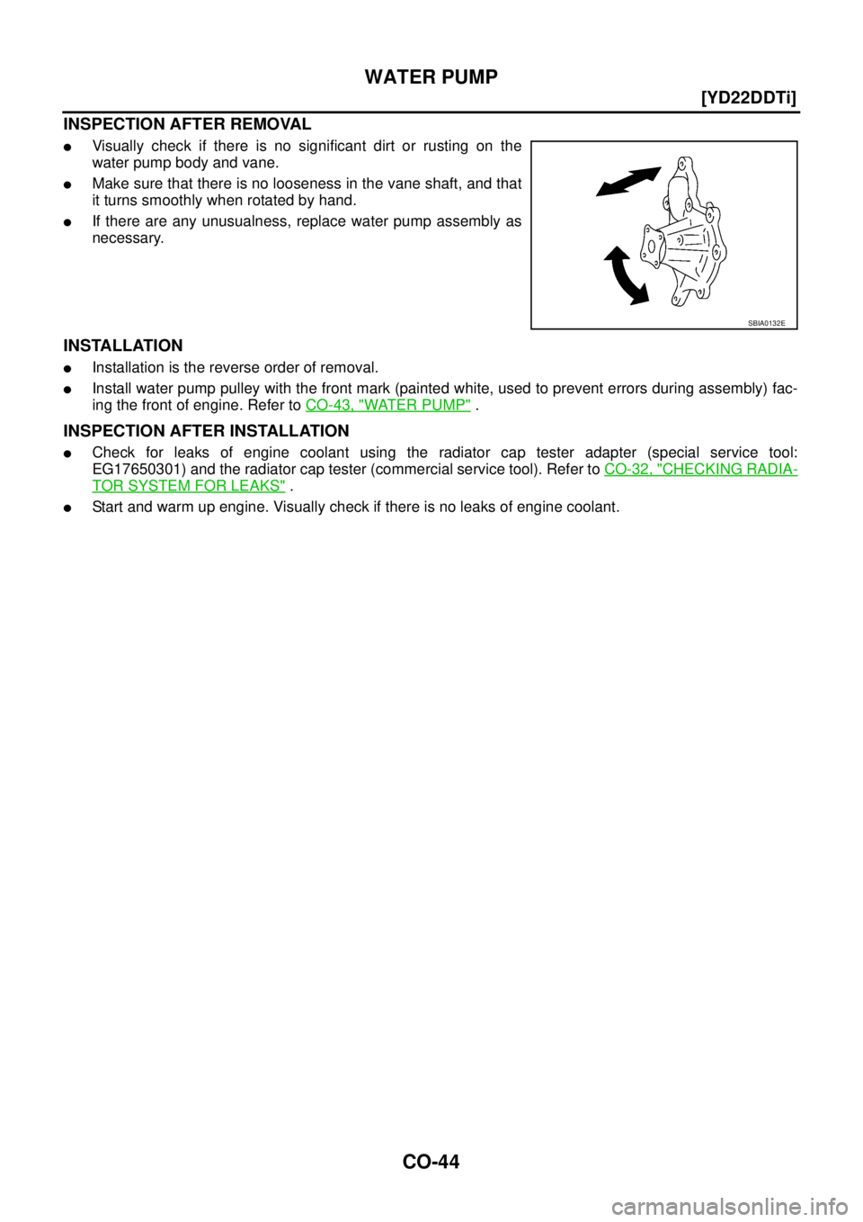
INSPECTION AFTER REMOVAL
�Visually check if there is no significant dirt or rusting on the
water pump body and vane.
�Make sure that there is no looseness in the vane shaft, and that
it turns smoothly when rotated by hand.
�If there are any unusualness, replace water pump assembly as
necessary.
INSTALLATION
�Installation is the reverse order of removal.
�Install water pump pulley with the front mark (painted white, used to prevent errors during assembly) fac-
ing the front of engine. Refer to CO-43, "
WATER PUMP" .
INSPECTION AFTER INSTALLATION
�Check for leaks of engine coolant using the radiator cap tester adapter (special service tool:
EG17650301) and the radiator cap tester (commercial service tool). Refer to CO-32, "
CHECKING RADIA-
TOR SYSTEM FOR LEAKS" .
�Start and warm up engine. Visually check if there is no leaks of engine coolant.
SBIA0132E
Page 403 of 4555
![NISSAN X-TRAIL 2005 Service Repair Manual SERVICE DATA AND SPECIFICATIONS (SDS)
CO-47
[YD22DDTi]
C
D
E
F
G
H
I
J
K
L
MA
CO
SERVICE DATA AND SPECIFICATIONS (SDS)PFP:00030
Standard and LimitEBS00CU0
CAPACITY
Unit: (lmp qt)
THERMOSTAT
RADIAT](/manual-img/5/57403/w960_57403-402.png "NISSAN X-TRAIL 2005 Service Repair Manual SERVICE DATA AND SPECIFICATIONS (SDS)
CO-47
[YD22DDTi]
C
D
E
F
G
H
I
J
K
L
MA
CO
SERVICE DATA AND SPECIFICATIONS (SDS)PFP:00030
Standard and LimitEBS00CU0
CAPACITY
Unit: (lmp qt)
THERMOSTAT
RADIAT")
SERVICE DATA AND SPECIFICATIONS (SDS)
CO-47
[YD22DDTi]
C
D
E
F
G
H
I
J
K
L
MA
CO
SERVICE DATA AND SPECIFICATIONS (SDS)PFP:00030
Standard and LimitEBS00CU0
CAPACITY
Unit: (lmp qt)
THERMOSTAT
RADIATOR
Unit: kPa (bar, kg/cm2 , psi)
Tightening TorqueEBS00BKE
Unit: N·m (kg-m, ft-lb)
Unit: N·m (kg-m, in-lb)*
Engine coolant capacity (With reservoir tank at “MAX” level) Approx 9.5 (8-3/8)
Reservoir tank0.7 (5/8)
Valve opening temperature 80 - 84°C (176 - 183°F)
Full open lift amount More than 10 mm/ 95°C (0.39 in/203°F)
Valve closing temperature More than 77°C (171°F)
Cap relief pressureStandard 78 - 98 (0.78 - 0.98, 0.8 - 1.0, 11 - 14)
Limit 59 (0.59, 0.6, 9)
Leakage test pressure 157 (1.57, 1.6, 23)
Air relief plug7.4 (0.75, 65)*
Radiator mounting bracket
Cooling fan assembly
Cooling fan
Cooling fan motor (RH and LH)5.5 (0.56, 49)*
5.5 (0.56, 49)*
3.43 (0.35, 30)*
4.41 (0.45, 39)*
Water pump
Water pump pulley
Water inlet
Thermostat housing
Water inlet pipe
Heater return pipe26.5 (2.7, 20)
8.5 (0.86, 75)*
25 (2.6, 18)
25 (2.6, 18)
25 (2.6, 18)
25 (2.6, 18)
Page 488 of 4555
![NISSAN X-TRAIL 2005 Service Repair Manual EC-84
[QR (WITH EURO-OBD)]
TROUBLE DIAGNOSIS
17. DETECT MALFUNCTIONING PART
Check the following.
�Check camshaft position sensor (PHASE) and circuit. Refer to EC-257, "DTC P0340 CMP SENSOR
(PHASE)"](/manual-img/5/57403/w960_57403-487.png "NISSAN X-TRAIL 2005 Service Repair Manual EC-84
[QR (WITH EURO-OBD)]
TROUBLE DIAGNOSIS
17. DETECT MALFUNCTIONING PART
Check the following.
�Check camshaft position sensor (PHASE) and circuit. Refer to EC-257, \"DTC P0340 CMP SENSOR
(PHASE)\"")
EC-84
[QR (WITH EURO-OBD)]
TROUBLE DIAGNOSIS
17. DETECT MALFUNCTIONING PART
Check the following.
�Check camshaft position sensor (PHASE) and circuit. Refer to EC-257, "DTC P0340 CMP SENSOR
(PHASE)" .
�Check crankshaft position sensor (POS) and circuit. Refer to EC-250, "DTC P0335 CKP SENSOR (POS)"
.
OK or NG
OK >> GO TO 18.
NG >> 1. Repair or replace.
2. GO TO 4.
18. CHECK ECM FUNCTION
1. Substitute another known-good ECM to check ECM function. (ECM may be the cause of an incident, but
this is a rare case.)
2. Perform initialization of NATS system and registration of all NATS ignition key IDs. Refer to BL-108,
"NATS (NISSAN ANTI-THEFT SYSTEM)" .
>> GO TO 4.
Symptom Matrix ChartEBS010LT
SYSTEM — BASIC ENGINE CONTROL SYSTEM
SYMPTOM
Reference
page
HARD/NO START/RESTART (EXCP. HA)
ENGINE STALL
HESITATION/SURGING/FLAT SPOT
SPARK KNOCK/DETONATION
LACK OF POWER/POOR ACCELERATION
HIGH IDLE/LOW IDLE
ROUGH IDLE/HUNTING
IDLING VIBRATION
SLOW/NO RETURN TO IDLE
OVERHEATS/WATER TEMPERATURE HIGH
EXCESSIVE FUEL CONSUMPTION
EXCESSIVE OIL CONSUMPTION
BATTERY DEAD (UNDER CHARGE)
Warranty symptom code AA AB AC AD AE AF AG AH AJ AK AL AM HA
Fuel Fuel pump circuit 11232 22 3 2EC-466
Fuel pressure regulator system334444444 4EC-49
Injector circuit 11232 22 2EC-451
Evaporative emission system 334444444 4EC-522
Air Positive crankcase ventilation sys-
tem334444444 41EC-527
Incorrect idle speed adjustment 33 1111 1EC-79
Electric throttle control actuator 112332222 2 2EC-294
,
EC-296
,
EC-306
,
EC-314
IgnitionIncorrect ignition timing adjustment33111 11 1EC-79
Ignition circuit 11222 22 2EC-440
Main power supply and ground circuit 22333 33 23EC-125