Page 280 of 4555
![NISSAN X-TRAIL 2005 Service Repair Manual EM-226
[YD22DDTi]
ENGINE ASSEMBLY
Removal and Installation (4WD Models)EBS00LRY
WARNING:
�Situate vehicle on a flat and solid surface.
�Place chocks at front and back of rear wheels.
�For engines no](/manual-img/5/57403/w960_57403-279.png "NISSAN X-TRAIL 2005 Service Repair Manual EM-226
[YD22DDTi]
ENGINE ASSEMBLY
Removal and Installation (4WD Models)EBS00LRY
WARNING:
�Situate vehicle on a flat and solid surface.
�Place chocks at front and back of rear wheels.
�For engines no")
EM-226
[YD22DDTi]
ENGINE ASSEMBLY
Removal and Installation (4WD Models)EBS00LRY
WARNING:
�Situate vehicle on a flat and solid surface.
�Place chocks at front and back of rear wheels.
�For engines not equipped with engine slingers, attach proper slingers and bolts described in
PARTS CATALOG.
CAUTION:
�Always be careful to work safely, avoid forceful or uninstructed operations.
�Do not start working until exhaust system and engine coolant are cool enough.
�If items or work required are not covered by the engine main body section, refer to the applicable
sections.
�Always use the support point specified for lifting.
�Use either 2-pole lift type or separate type lift as best you can. If board-on type is used for
unavoidable reasons, support at the rear axle jacking point with transmission jack or similar tool
before starting work, in preparation for the backward shift of center of gravity.
�For supporting points for lifting and jacking point at rear axle, refer to GI-36, "Garage Jack and
Safety Stand" .
1. Rear engine mounting insulator 2. Rear engine mounting bracket 3. RH engine mounting insulator
4. RH engine mounting bracket 5. Front engine mounting bracket 6. Front engine mounting insulator
7. Grommet 8. Center member 9. LH engine mounting insulator
10. Stopper 11. LH engine mounting bracket
PBIC3902E
Page 281 of 4555
![NISSAN X-TRAIL 2005 Service Repair Manual ENGINE ASSEMBLY
EM-227
[YD22DDTi]
C
D
E
F
G
H
I
J
K
L
MA
EM
REMOVAL
Description of work
Remove engine, transaxle and transfer assembly with front suspension member from vehicle downward. Sep-
arate](/manual-img/5/57403/w960_57403-280.png "NISSAN X-TRAIL 2005 Service Repair Manual ENGINE ASSEMBLY
EM-227
[YD22DDTi]
C
D
E
F
G
H
I
J
K
L
MA
EM
REMOVAL
Description of work
Remove engine, transaxle and transfer assembly with front suspension member from vehicle downward. Sep-
arate")
ENGINE ASSEMBLY
EM-227
[YD22DDTi]
C
D
E
F
G
H
I
J
K
L
MA
EM
REMOVAL
Description of work
Remove engine, transaxle and transfer assembly with front suspension member from vehicle downward. Sep-
arate suspension member, and then separate engine and transaxle.
Preparation
1. Remove hood assembly. Refer to BL-12, "HOOD" .
2. Drain engine coolant from radiator drain plug. Refer to CO-32, "
DRAINING ENGINE COOLANT" .
3. Remove the following parts.
�LH and RH engine undercover
�LH and RH front wheels
�Battery; Refer to SC-4, "BATTERY" .
�Drive belts; Refer to EM-141, "Removal and Installation" .
�Air duct and air cleaner case assembly; Refer to EM-142, "Removal and Installation" .
�Alternator; Refer to SC-17, "Removal and Installation" .
�Radiator and cooling fan assembly; Refer to CO-35, "Removal and Installation" and CO-37, "COOL-
ING FAN" .
�Charge air cooler; Refer to EM-144, "CHARGE AIR COOLER" .
4. Disconnect engine room harness from the engine side and set it aside for easier work.
5. Disconnect all vacuum hoses and air hoses connected to vehicle side at engine side.
Engine room LH
1. Disconnect fuel hose, and plug it to prevent fuel from draining. Refer to EM-146, "INTAKE MANIFOLD" .
2. Disconnect heater hose, and install plug it to prevent engine coolant from draining. Refer to EM-146,
"INTAKE MANIFOLD" .
3. Remove clutch operating cylinder from transaxle, and move it aside. Refer to MT-19, "
TRANSAXLE
ASSEMBLY" and CL-12, "OPERATING CYLINDER" .
4. Disconnect shift cable from transaxle. Refer to MT-16, "
CONTROL LINKAGE" .
Engine room RH
1. Remove engine coolant reservoir tank. Refer to CO-35, "RADIATOR" .
2. Remove A/C compressor with piping connected from engine. Temporarily secure it on body with a rope to
avoid putting load on it. Refer to ATC-144, "
Removal and Installation of Compressor" .
Vehicle underbody
1. Remove exhaust front tube. Refer to EX-2, "Removal and Installation" .
2. Remove propeller shaft. Refer to PR-4, "
Removal and Installation" .
3. Remove steering shaft from steering gear. Refer to PS-11, "
STEERING COLUMN" .
4. Disconnect power steering fluid cooler piping at a point between body and engine. Refer to PS-37,
"HYDRAULIC LINE" .
5. Remove front wheel sensor (LH and RH) for ABS from brake caliper. Refer to BRC-46, "
WHEEL SEN-
SORS" (ABS), BRC-116, "WHEEL SENSORS" (ESP/TCS/ABS).
6. Remove brake caliper with piping connected from steering knuckle. Temporarily secure it on body with a
rope to avoid load on it. Refer to BR-27, "
FRONT DISC BRAKE" .
7. Remove lower ends of LH and RH strut from steering knuckle. Refer to FSU-5, "
FRONT SUSPENSION
ASSEMBLY" .
8. Preparation for the separation work of transaxle as follows:
a. Remove crankshaft position sensor from transmission. Refer toEM-157, "
OIL PAN AND OIL STRAINER" .
b. Remove transaxle joint bolts which pierce at oil pan lower rear side. Refer to EM-157, "
OIL PAN AND OIL
STRAINER" .
Page 285 of 4555
![NISSAN X-TRAIL 2005 Service Repair Manual CYLINDER BLOCK
EM-231
[YD22DDTi]
C
D
E
F
G
H
I
J
K
L
MA
EM
DISASSEMBLY
1. Remove engine, transaxle and transfer assembly from the vehicle, then separate engine and transaxle
and transfer assembly. R](/manual-img/5/57403/w960_57403-284.png "NISSAN X-TRAIL 2005 Service Repair Manual CYLINDER BLOCK
EM-231
[YD22DDTi]
C
D
E
F
G
H
I
J
K
L
MA
EM
DISASSEMBLY
1. Remove engine, transaxle and transfer assembly from the vehicle, then separate engine and transaxle
and transfer assembly. R")
CYLINDER BLOCK
EM-231
[YD22DDTi]
C
D
E
F
G
H
I
J
K
L
MA
EM
DISASSEMBLY
1. Remove engine, transaxle and transfer assembly from the vehicle, then separate engine and transaxle
and transfer assembly. Refer to EM-222, "
ENGINE ASSEMBLY" .
2. Remove clutch cover and disk. Refer to CL-16, "
CLUTCH DISC, CLUTCH COVER AND FLYWHEEL" .
3. Install engine to engine stand as follows:
a. Remove flywheel.
b. Secure ring gear with the ring gear stopper (special service
tool), then loosen mounting bolts with TORX socket (size: T55,
Commercial Service Tools) and remove them. As an alternative
method hold crankshaft pulley with the pulley holder (special
service tool: KV10109300) to remove flywheel.
CAUTION:
�Do not disassemble flywheel.
�Do not place flywheel with signal plate facing down.
�When handling signal plate, take care not to damage or
scratch it.
�Handle signal plate in a manner that prevents it from
becoming magnetized.
c. Install the engine sub-attachment (special service tool) to the
rear side of cylinder block.
�Align knock pins on cylinder block with pin holes on attach-
ment to install.
NOTE:
Installation bolts are part of engine sub-attachment.
d. Install the engine stand shaft (special service tool).
NOTE:
Use commercially available M12 (0.47 in) mounting bolts and
nuts (4 sets) with strength grade of 9T (minimum).
1. Rear oil seal retainer 2. Cylinder block 3. Oil pressure switch
4. Fuel pump bracket 5. Oil level gauge guide 6. Top ring
7. Second ring 8. Oil ring 9. Oil jet
10. Piston pin 11. Snap ring 12. Piston
13. Main bearing upper 14. Thrust bearing 15. Connecting rod
16. Key 17. Connecting rod bearing 18. Connecting rod cap
19. Connecting rod nut 20. Main bearing lower 21. Crankshaft
22. Main bearing cap bolt 23. Main bearing cap 24. Pilot bushing
25. Flywheel 26. Washer 27. Oil jet relief valve
28. Drain plug 29. Rear oil seal
PBIC2406E
JEM192G
Page 294 of 4555
![NISSAN X-TRAIL 2005 Service Repair Manual EM-240
[YD22DDTi]
CYLINDER BLOCK
18. Install rear oil seal retainer to cylinder block.
�Apply new engine oil to the oil and dust seal lips.
�Apply liquid gasket to rear oil seal retainer using the t](/manual-img/5/57403/w960_57403-293.png "NISSAN X-TRAIL 2005 Service Repair Manual EM-240
[YD22DDTi]
CYLINDER BLOCK
18. Install rear oil seal retainer to cylinder block.
�Apply new engine oil to the oil and dust seal lips.
�Apply liquid gasket to rear oil seal retainer using the t")
EM-240
[YD22DDTi]
CYLINDER BLOCK
18. Install rear oil seal retainer to cylinder block.
�Apply new engine oil to the oil and dust seal lips.
�Apply liquid gasket to rear oil seal retainer using the tube
presser (special service tool: WS39930000) as shown in the
figure.
Use Genuine Liquid Gasket or equivalent.
19. Press fit pilot bush into crankshaft.
�Using the drift with outer diameter of 19 mm (0.75 in), press fit
pilot bush until it stops.
20. Install fuel pump bracket.
�Align the bracket with the dowel pins on cylinder block to
install.
�The two bolts used for dowel pins have a longer shanks than
the other two.
21. Install parts to engine in the reverse order of disassembly.
22. Remove engine from engine stand in the reverse order of assembly.
23. Install flywheel.
�When installing flywheel to crankshaft, be sure to correctly
align crankshaft side dowel pin and flywheel side dowel pin
hole.
CAUTION:
If these are not aligned correctly, engine runs roughly
and “MI” turns on.
JEM233G
JEM234G
PBIC2329E
PBIC2538E
Page 321 of 4555
SERVICE DATA AND SPECIFICATIONS (SDS)
EM-267
[YD22DDTi]
C
D
E
F
G
H
I
J
K
L
MA
EM
*1 Rocker cover1)
7.8 (0.8, 69)*2
2)
7.8 (0.8, 69) *2
*1 Camshaft bracket 13 to 15 bolts 1) 2 (0.2, 1)
1 to 12 bolts 2) 2 (0.2, 1)
3) 6 (0.6, 4)
4) 12.5 (1.3, 9)
*1 Front chain case
7.9 (0.8, 70)*
2
Chain tensioner
9.6 (0.98, 85)*2
Tension guide23.5 (2.4, 18)
Slack guide23.5 (2.4, 18)
Camshaft sprocket 143 (15, 105)
*1 Oil pump housing12.5 (1.3, 9)
Power steering oil pump 53.5 (5.5, 39)
*1 Rear chain case12.5 (1.3, 9)
Engine coolant temperature sensor 13.5 (1.4, 10)
*1 Cylinder head 1) 39.2 (4.0, 29)
2) 180 degrees
3) 0 (0, 0)
4) 39.2 (4.0, 29)
5) 90 degrees (angle tightening)
6) 90 degrees (angle tightening)
Glow plug20.5 (2.1, 15)
*1 Flywheel108 (11, 80)
Oil pressure switch15 (1.5, 11)
Oil jet
8.4 (0.86, 74)*
2
Oil jet relief valve49 (5.0, 36)
Rear oil seal retainer12.5 (1.3, 9)
Page 2152 of 4555
CL-16
CLUTCH DISC, CLUTCH COVER AND FLYWHEEL
CLUTCH DISC, CLUTCH COVER AND FLYWHEELPFP:30100
Removal and InstallationECS008BG
COMPONENTS
QR engine models
YD engine models
CAUTION:
Be careful not to bring any grease to the clutch disc facing, pressure plate surface and flywheel sur-
face.
REMOVAL
1. Remove manual transaxle from the vehicle. Refer to MT-19, "Removal and Installation"
2. Loosen clutch cover mounting bolts evenly. Then remove clutch cover and clutch disc.
PCIB0768E
1. Flywheel 2. Clutch disc 3. Clutch cover
PCIB0769E
1. Flywheel 2. Clutch disc 3. Clutch cover
Page 2154 of 4555
CL-18
CLUTCH DISC, CLUTCH COVER AND FLYWHEEL
INSTALLATION
1. Apply recommended grease to clutch disc and input shaft splines.
CAUTION:
Be sure to apply grease to the points specified. Otherwise, noise, poor disengagement, or damage
to the clutch may result. Excessive grease may cause slip or judder. Wipe off any grease oozing
from the parts.
2. Install clutch disc and clutch cover. Pre-tighten mounting bolts
and install clutch aligning bar.
3. Tighten clutch cover mounting bolts evenly in two steps in the
order shown in the figure. Refer to CL-16, "
COMPONENTS" .
4. Install manual transaxle. Refer to MT-19, "
Removal and Installa-
tion" . Tool number
QR engine models : KV30101600
YD engine models : KV30100100SCIA0909E
Page 2332 of 4555
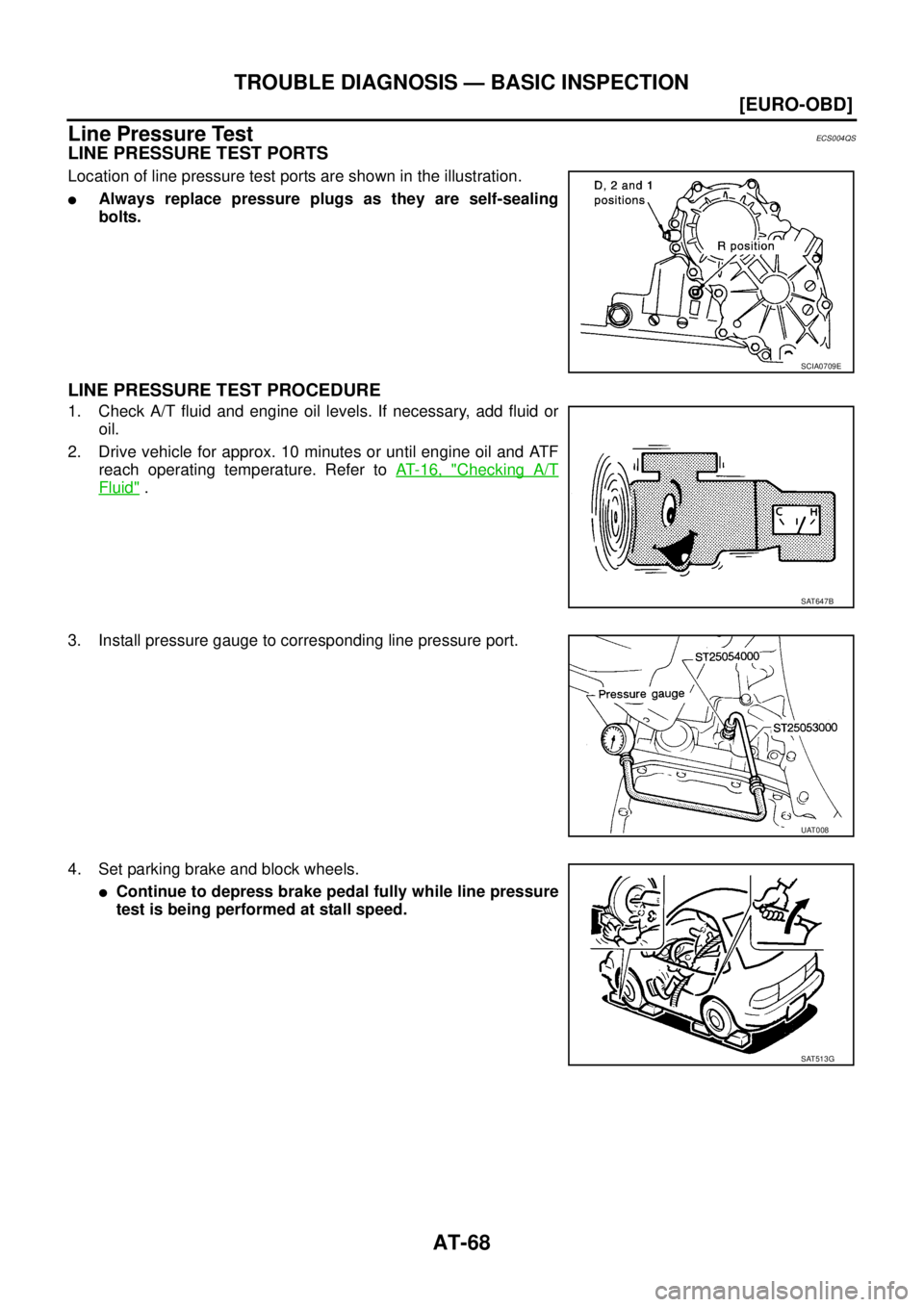
AT-68
[EURO-OBD]
TROUBLE DIAGNOSIS — BASIC INSPECTION
Line Pressure TestECS004QS
LINE PRESSURE TEST PORTS
Location of line pressure test ports are shown in the illustration.
�Always replace pressure plugs as they are self-sealing
bolts.
LINE PRESSURE TEST PROCEDURE
1. Check A/T fluid and engine oil levels. If necessary, add fluid or
oil.
2. Drive vehicle for approx. 10 minutes or until engine oil and ATF
reach operating temperature. Refer to AT- 1 6 , "
Checking A/T
Fluid" .
3. Install pressure gauge to corresponding line pressure port.
4. Set parking brake and block wheels.
�Continue to depress brake pedal fully while line pressure
test is being performed at stall speed.
SCIA0709E
SAT647B
UAT008
SAT513G
![NISSAN X-TRAIL 2005 Service Repair Manual SERVICE DATA AND SPECIFICATIONS (SDS)
EM-267
[YD22DDTi]
C
D
E
F
G
H
I
J
K
L
MA
EM
*1 Rocker cover1)
7.8 (0.8, 69)*2
2)
7.8 (0.8, 69) *2
*1 Camshaft bracket 13 to 15 bolts 1) 2 (0.2, 1)
1 to 12 bolt](/manual-img/5/57403/w960_57403-320.png "NISSAN X-TRAIL 2005 Service Repair Manual SERVICE DATA AND SPECIFICATIONS (SDS)
EM-267
[YD22DDTi]
C
D
E
F
G
H
I
J
K
L
MA
EM
*1 Rocker cover1)
7.8 (0.8, 69)*2
2)
7.8 (0.8, 69) *2
*1 Camshaft bracket 13 to 15 bolts 1) 2 (0.2, 1)
1 to 12 bolt")