Page 3877 of 4555

INSTRUMENT PANEL ASSEMBLY
IP-11
C
D
E
F
G
H
J
K
L
MA
B
IP
Removal and InstallationEIS008BT
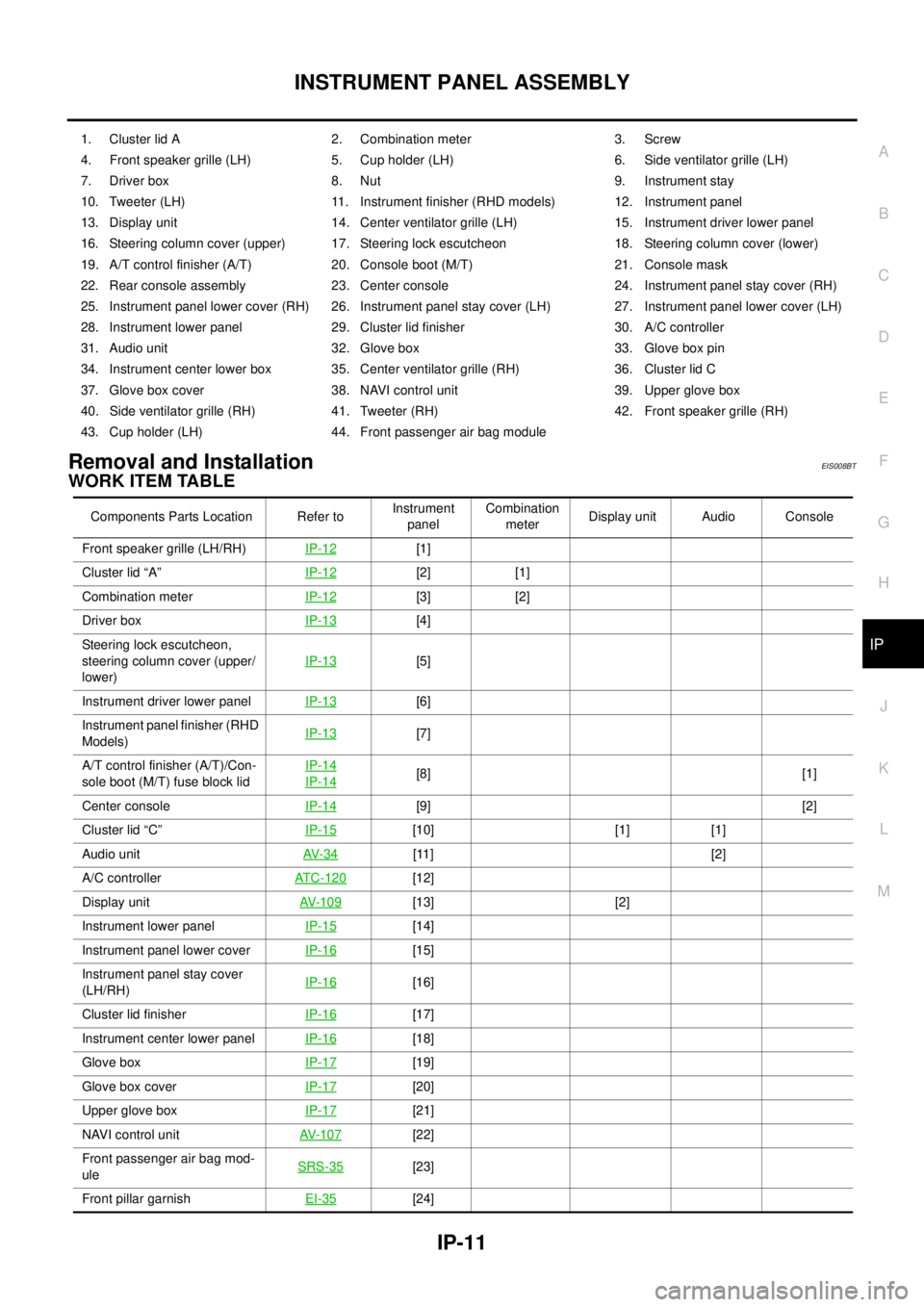
WORK ITEM TABLE
1. Cluster lid A 2. Combination meter 3. Screw
4. Front speaker grille (LH) 5. Cup holder (LH) 6. Side ventilator grille (LH)
7. Driver box 8. Nut 9. Instrument stay
10. Tweeter (LH) 11. Instrument finisher (RHD models) 12. Instrument panel
13. Display unit 14. Center ventilator grille (LH) 15. Instrument driver lower panel
16. Steering column cover (upper) 17. Steering lock escutcheon 18. Steering column cover (lower)
19. A/T control finisher (A/T) 20. Console boot (M/T) 21. Console mask
22. Rear console assembly 23. Center console 24. Instrument panel stay cover (RH)
25. Instrument panel lower cover (RH) 26. Instrument panel stay cover (LH) 27. Instrument panel lower cover (LH)
28. Instrument lower panel 29. Cluster lid finisher 30. A/C controller
31. Audio unit 32. Glove box 33. Glove box pin
34. Instrument center lower box 35. Center ventilator grille (RH) 36. Cluster lid C
37. Glove box cover 38. NAVI control unit 39. Upper glove box
40. Side ventilator grille (RH) 41. Tweeter (RH) 42. Front speaker grille (RH)
43. Cup holder (LH) 44. Front passenger air bag module
Components Parts Location Refer toInstrument
panelCombination
meterDisplay unit Audio Console
Front speaker grille (LH/RH)IP-12
[1]
Cluster lid “A”IP-12
[2] [1]
Combination meterIP-12
[3] [2]
Driver boxIP-13
[4]
Steering lock escutcheon,
steering column cover (upper/
lower)IP-13
[5]
Instrument driver lower panel IP-13
[6]
Instrument panel finisher (RHD
Models)IP-13
[7]
A/T control finisher (A/T)/Con-
sole boot (M/T) fuse block lidIP-14
IP-14[8] [1]
Center consoleIP-14
[9] [2]
Cluster lid “C”IP-15
[10] [1] [1]
Audio unitAV- 3 4
[11] [2]
A/C controllerATC-120
[12]
Display unitAV- 1 0 9
[13] [2]
Instrument lower panelIP-15
[14]
Instrument panel lower cover IP-16
[15]
Instrument panel stay cover
(LH/RH)IP-16
[16]
Cluster lid finisherIP-16
[17]
Instrument center lower panelIP-16
[18]
Glove boxIP-17
[19]
Glove box coverIP-17
[20]
Upper glove boxIP-17
[21]
NAVI control unitAV- 1 0 7
[22]
Front passenger air bag mod-
uleSRS-35
[23]
Front pillar garnishEI-35
[24]
Page 3883 of 4555
INSTRUMENT PANEL ASSEMBLY
IP-17
C
D
E
F
G
H
J
K
L
MA
B
IP
Glove Box
Open glove box, and remove glove box pin from inside.
Glove Box Cover
1. Remove screw.
2. Remove relay clamp installed to back of glove box cover.
3. Pull it forward to remove.
Upper Glove Box
Disengage pawls and clips, and then pull it straight forward.
Passenger Air Bag Module
Remove passenger air bag module after removing bolts. Refer to SRS-35, "FRONT PASSENGER AIR BAG
MODULE" in SRS section.
Instrument Mask
Insert a screwdriver wrapped with a shop cloth into cutout on instrument mask. Disengage tab to remove.
Front Pillar Garnish
Pull straight front pillar garnish toward vehicle inside of right and left. Remove metal clip to remove.
Refer to EI-35, "
Removal and Installation" in EI section.
PIIA9919E
PIIA9909E
PIIA9910E
Page 3946 of 4555
MTC-22
BLOWER UNIT
BLOWER UNITPFP:27200
Removal and InstallationEJS004YB
REMOVAL
1. Remove glove box assembly.
2. Remove glove box cover, instrument passenger lower panel and instrument reinforcement. Refer to IP-11,
"Removal and Installation" .
3. Remove ECM with ECM bracket attached.
4. Remove instrument panel mounting screw.
5. Remove blower unit mounting bolt and screw.
6. Disconnect blower motor connector and fan resistor connector.
7. Disconnect intake door motor connector and harness clips.
8. Remove blower unit.
CAUTION:
Slide the blower unit toward the right, remove location pins
(2 pieces), then move it downward.
INSTALLATION
Installation is basically the reverse order of removal.
CAUTION:
�Make sure location pins (2 pieces) are securely installed.
RJIA3161E
Page 3949 of 4555
BLOWER FAN RESISTOR
MTC-25
C
D
E
F
G
H
I
K
L
MA
B
MTC
BLOWER FAN RESISTORPFP:27150
Removal and InstallationEJS004HE
REMOVAL
1. Remove glove box cover. Refer to IP-11, "Removal and Installation" .
2. Remove mounting screws, and then remove fan resistor.
CAUTION:
Do not repair the thermal fuse of the fan resistor.
INSTALLATION
Installation is basically the reverse order of removal.
RJIA0093E
Page 4244 of 4555

WW-32
POWER SOCKET
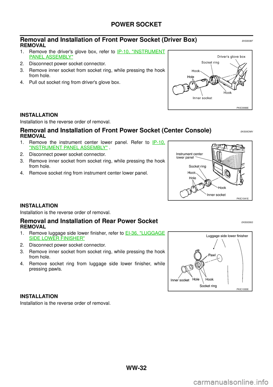
Removal and Installation of Front Power Socket (Driver Box)EKS0036F
REMOVAL
1. Remove the driver's glove box, refer to IP-10, "INSTRUMENT
PANEL ASSEMBLY"
2. Disconnect power socket connector.
3. Remove inner socket from socket ring, while pressing the hook
from hole.
4. Pull out socket ring from driver's glove box.
INSTALLATION
Installation is the reverse order of removal.
Removal and Installation of Front Power Socket (Center Console)EKS00OMV
REMOVAL
1. Remove the instrument center lower panel. Refer to IP-10,
"INSTRUMENT PANEL ASSEMBLY" .
2. Disconnect power socket connector.
3. Remove inner socket from socket ring, while pressing the hook
from hole.
4. Remove socket ring from instrument center lower panel.
INSTALLATION
Installation is the reverse order of removal.
Removal and Installation of Rear Power SocketEKS0036G
REMOVAL
1. Remove luggage side lower finisher, refer to EI-36, "LUGGAGE
SIDE LOWER FINISHER"
2. Disconnect power socket connector.
3. Remove inner socket from socket ring, while pressing the hook
from hole.
4. Remove socket ring from luggage side lower finisher, while
pressing pawls.
INSTALLATION
Installation is the reverse order of removal.
PKIC0999E
PKIC1041E
PKIC1000E