2005 NISSAN X-TRAIL brake sensor
[x] Cancel search: brake sensorPage 4159 of 4555

COMBINATION METERS
DI-11
C
D
E
F
G
H
I
J
L
MA
B
DI
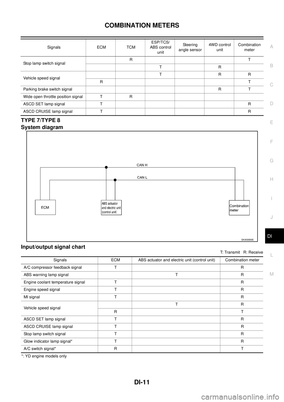
TYPE 7/TYPE 8
System diagram
Input/output signal chart
T: Transmit R: Receive
*: YD engine models onlyStop lamp switch signalRT
TR
Vehicle speed signalTRR
RT
Parking brake switch signalRT
Wide open throttle position signal T R
ASCD SET lamp signal TR
ASCD CRUISE lamp signal TR Signals ECM TCMESP/TCS/
ABS control
unitSteering
angle sensor4WD control
unitCombination
meter
SKIA9999E
Signals ECM ABS actuator and electric unit (control unit) Combination meter
A/C compressor feedback signal T R
ABS warning lamp signal T R
Engine coolant temperature signal T R
Engine speed signal T R
MI signal T R
Vehicle speed signalTR
RT
ASCD SET lamp signal T R
ASCD CRUISE lamp signal T R
Stop lamp switch signal T R
Glow indicator lamp signal* T R
A/C switch signal* R T
Page 4160 of 4555

DI-12
COMBINATION METERS
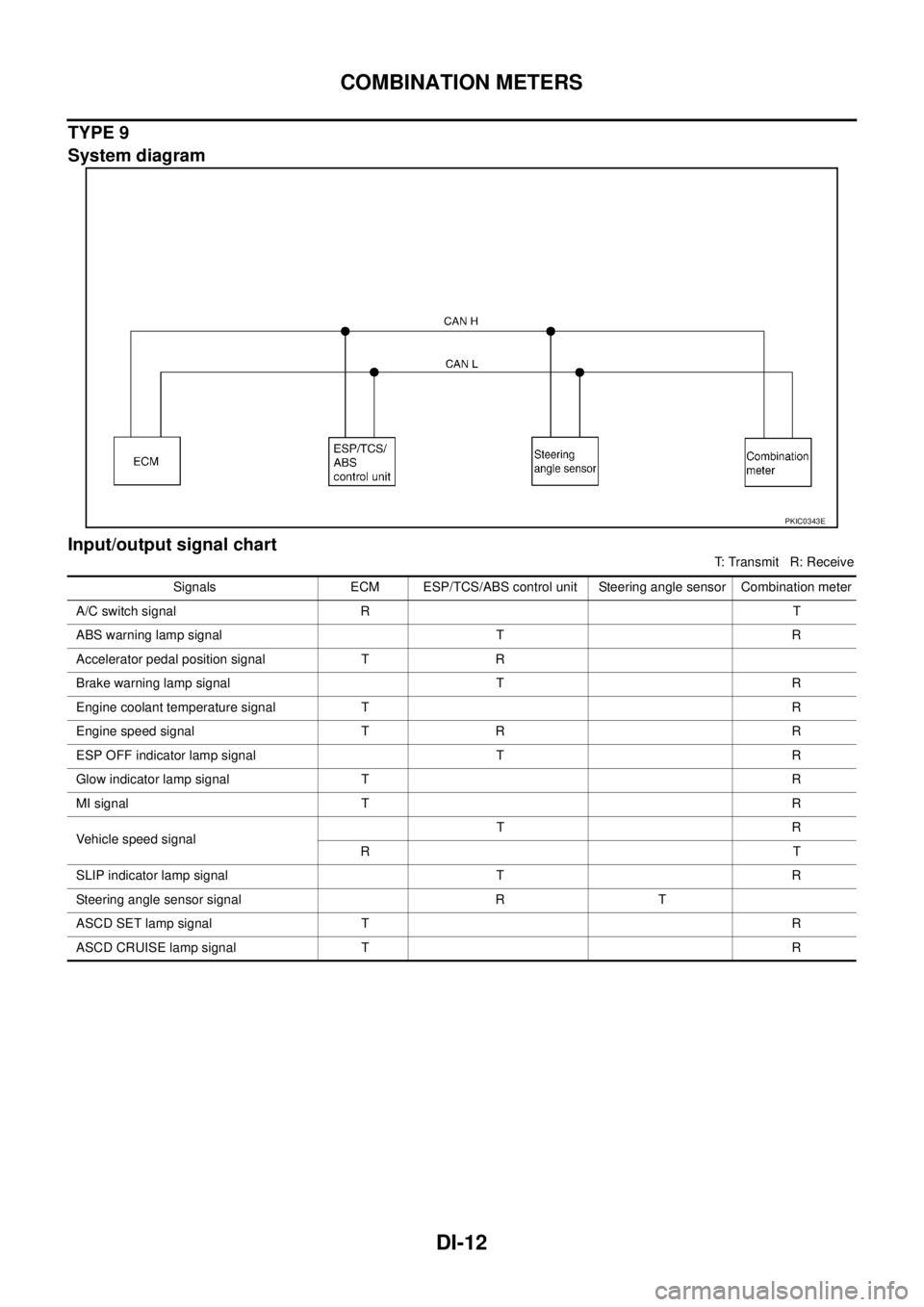
TYPE 9
System diagram
Input/output signal chart
T: Transmit R: Receive
PKIC0343E
Signals ECM ESP/TCS/ABS control unit Steering angle sensor Combination meter
A/C switch signal RT
ABS warning lamp signal T R
Accelerator pedal position signal T R
Brake warning lamp signal T R
Engine coolant temperature signal TR
Engine speed signal T R R
ESP OFF indicator lamp signal T R
Glow indicator lamp signal TR
MI signal TR
Vehicle speed signalTR
RT
SLIP indicator lamp signal T R
Steering angle sensor signal R T
ASCD SET lamp signal TR
ASCD CRUISE lamp signal TR
Page 4248 of 4555
![NISSAN X-TRAIL 2005 Service Repair Manual LAN-4
[CAN]
CAN COMMUNICATION
CAN COMMUNICATIONPFP:23710
System DescriptionEKS001U3
CAN (Controller Area Network) is a serial communication line for real time application. It is an on-vehicle mul-
t NISSAN X-TRAIL 2005 Service Repair Manual LAN-4
[CAN]
CAN COMMUNICATION
CAN COMMUNICATIONPFP:23710
System DescriptionEKS001U3
CAN (Controller Area Network) is a serial communication line for real time application. It is an on-vehicle mul-
t](/manual-img/5/57403/w960_57403-4247.png)
LAN-4
[CAN]
CAN COMMUNICATION
CAN COMMUNICATIONPFP:23710
System DescriptionEKS001U3
CAN (Controller Area Network) is a serial communication line for real time application. It is an on-vehicle mul-
tiplex communication line with high data communication speed and excellent error detection ability. Many elec-
tronic control units are equipped onto a vehicle, and each control unit shares information and links with other
control units during operation (not independent). In CAN communication, control units are connected with 2
communication lines (CAN H line, CAN L line) allowing a high rate of information transmission with less wiring.
Each control unit transmits/receives data but selectively reads required data only.
CAN Communication UnitEKS00EGL
Go to CAN system, when selecting your CAN system type from the following table.
TYPE 1/TYPE 2
System diagram
Body type Wagon
Axle 4WD 2WD
Engine YD22DDTi QR20DE/QR25DE YD22DDTi QR25DE QR20DE YD22DDTi
Transmission M/T A/T M/T A/T M/T
Brake control ABS ESP ABS ESP
CAN system type 1 2 3 4 5 6 7 8 9
CAN system trouble diagnosisLAN-11
LAN-27LAN-43LAN-68LAN-
86
LAN-
104LAN-130LAN-
143
LAN-
156
ECM×××××××××
TCM××
ESP/TCS/ABS control unit××× ×
ABS actuator and electric unit
(control unit)××× ××
Steering angle sensor××× ×
4WD control unit××××××
Combination meter×××××××××
PKIA6458E
Page 4251 of 4555
![NISSAN X-TRAIL 2005 Service Repair Manual CAN COMMUNICATION
LAN-7
[CAN]
C
D
E
F
G
H
I
J
L
MA
B
LAN
Input/output signal chart
T: Transmit R: Receive
*1: YD engine models only
*2: QR engine models only
TYPE 6
System diagram
Signals ECMESP/T NISSAN X-TRAIL 2005 Service Repair Manual CAN COMMUNICATION
LAN-7
[CAN]
C
D
E
F
G
H
I
J
L
MA
B
LAN
Input/output signal chart
T: Transmit R: Receive
*1: YD engine models only
*2: QR engine models only
TYPE 6
System diagram
Signals ECMESP/T](/manual-img/5/57403/w960_57403-4250.png)
CAN COMMUNICATION
LAN-7
[CAN]
C
D
E
F
G
H
I
J
L
MA
B
LAN
Input/output signal chart
T: Transmit R: Receive
*1: YD engine models only
*2: QR engine models only
TYPE 6
System diagram
Signals ECMESP/TCS/ABS
control unitSteering angle
sensor4WD control
unitCombination
meter
4WD mode indicator lamp signalTR
4WD warning lamp signalTR
A/C compressor feedback signal*
2TR
A/C switch signal*
1RT
ABS warning lamp signal T R
Accelerator pedal position signal T R R
Brake warning lamp signal T R
Engine coolant temperature signal TR
Engine speed signal T R R R
ESP OFF indicator lamp signal T R
Glow indicator lamp signal*1 TR
MI signal TR
Stop lamp switch signal T R
Vehicle speed signalTRR
RT
SLIP indicator lamp signal T R
Parking brake switch signalRT
Steering angle sensor signal R T
ASCD SET lamp signal TR
ASCD CRUISE lamp signal TR
PKIA9635E
Page 4252 of 4555
![NISSAN X-TRAIL 2005 Service Repair Manual LAN-8
[CAN]
CAN COMMUNICATION
Input/output signal chart
T: Transmit R: Receive
Signals ECM TCMESP/TCS/
ABS control
unitSteering
angle sensor4WD control
unitCombination
meter
4WD mode indicator NISSAN X-TRAIL 2005 Service Repair Manual LAN-8
[CAN]
CAN COMMUNICATION
Input/output signal chart
T: Transmit R: Receive
Signals ECM TCMESP/TCS/
ABS control
unitSteering
angle sensor4WD control
unitCombination
meter
4WD mode indicator](/manual-img/5/57403/w960_57403-4251.png)
LAN-8
[CAN]
CAN COMMUNICATION
Input/output signal chart
T: Transmit R: Receive
Signals ECM TCMESP/TCS/
ABS control
unitSteering
angle sensor4WD control
unitCombination
meter
4WD mode indicator lamp signalTR
4WD warning lamp signalTR
A/C compressor feedback signal TR
A/T position indicator lamp signal T R R
A/T self-diagnosis signal R T
ABS warning lamp signal T R
Accelerator pedal position signal T R R
Brake warning lamp signal T R
Closed throttle position signal T R
Engine and A/T integratedTR
RT
Engine coolant temperature signal TR
Engine speed signal T R R R
ESP OFF indicator lamp signal T R
MI signal TR
O/D OFF indicator signal T R
Output shaft revolution signal R T
Overdrive control switch signal R T
P·N range signal R T
SLIP indicator lamp signal T R
Steering angle sensor signal R T
Stop lamp switch signalRT
TR
Vehicle speed signalTRR
RT
Parking brake switch signalRT
Wide open throttle position signal T R
ASCD SET lamp signal TR
ASCD CRUISE lamp signal TR
Page 4254 of 4555
![NISSAN X-TRAIL 2005 Service Repair Manual LAN-10
[CAN]
CAN COMMUNICATION
TYPE 9
System diagram
Input/output signal chart
T: Transmit R: Receive
PKIC0343E
Signals ECM ESP/TCS/ABS control unit Steering angle sensor Combination meter
A/C swi NISSAN X-TRAIL 2005 Service Repair Manual LAN-10
[CAN]
CAN COMMUNICATION
TYPE 9
System diagram
Input/output signal chart
T: Transmit R: Receive
PKIC0343E
Signals ECM ESP/TCS/ABS control unit Steering angle sensor Combination meter
A/C swi](/manual-img/5/57403/w960_57403-4253.png)
LAN-10
[CAN]
CAN COMMUNICATION
TYPE 9
System diagram
Input/output signal chart
T: Transmit R: Receive
PKIC0343E
Signals ECM ESP/TCS/ABS control unit Steering angle sensor Combination meter
A/C switch signal RT
ABS warning lamp signal T R
Accelerator pedal position signal T R
Brake warning lamp signal T R
Engine coolant temperature signal TR
Engine speed signal T R R
ESP OFF indicator lamp signal T R
Glow indicator lamp signal TR
MI signal TR
Vehicle speed signalTR
RT
SLIP indicator lamp signal T R
Steering angle sensor signal R T
ASCD SET lamp signal TR
ASCD CRUISE lamp signal TR
Page 4481 of 4555

HARNESS
PG-65
C
D
E
F
G
H
I
J
L
MA
B
PG
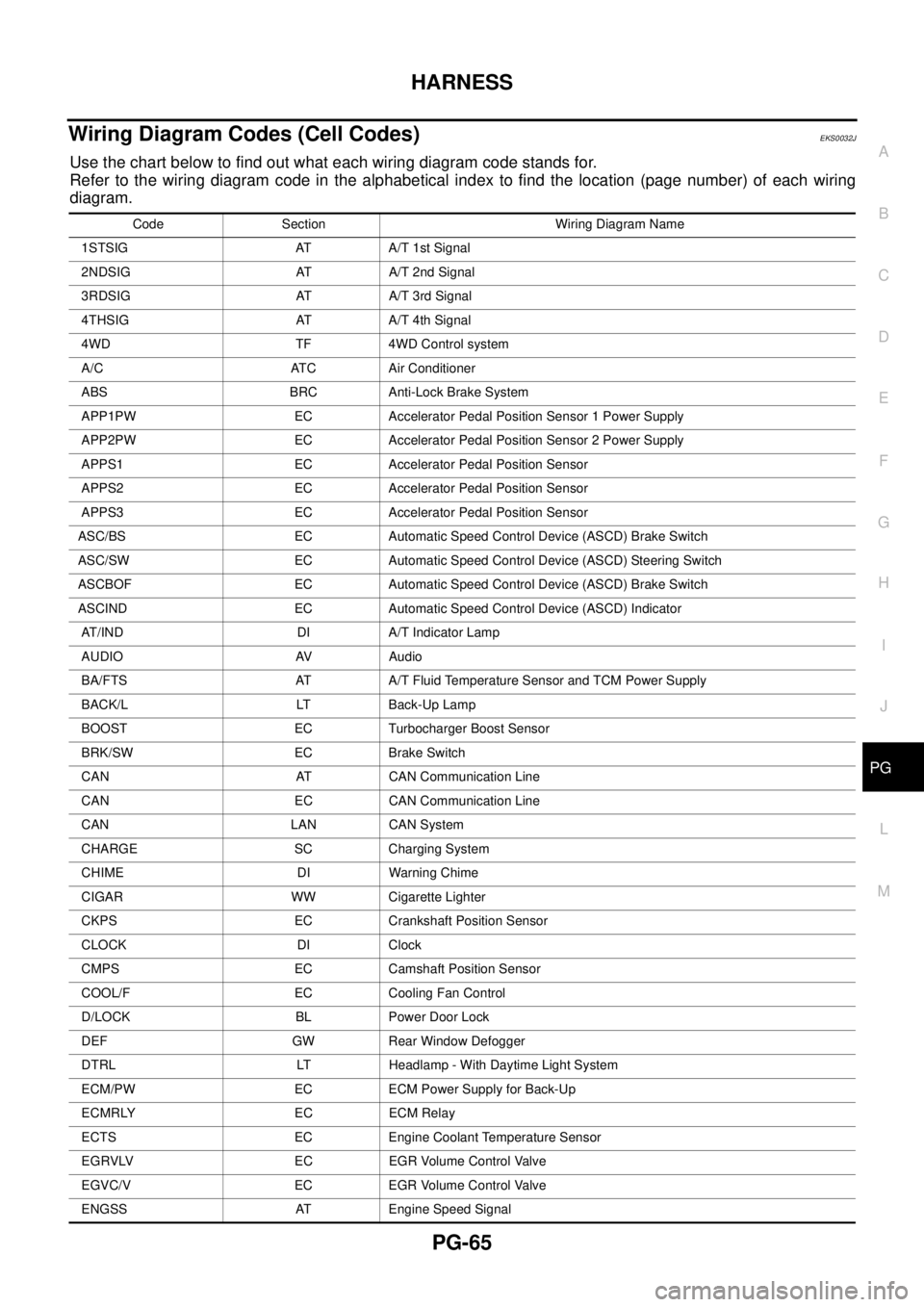
Wiring Diagram Codes (Cell Codes) EKS0032J
Use the chart below to find out what each wiring diagram code stands for.
Refer to the wiring diagram code in the alphabetical index to find the location (page number) of each wiring
diagram.
Code Section Wiring Diagram Name
1STSIG AT A/T 1st Signal
2NDSIG AT A/T 2nd Signal
3RDSIG AT A/T 3rd Signal
4THSIG AT A/T 4th Signal
4WD TF 4WD Control system
A/C ATC Air Conditioner
ABS BRC Anti-Lock Brake System
APP1PW EC Accelerator Pedal Position Sensor 1 Power Supply
APP2PW EC Accelerator Pedal Position Sensor 2 Power Supply
APPS1 EC Accelerator Pedal Position Sensor
APPS2 EC Accelerator Pedal Position Sensor
APPS3 EC Accelerator Pedal Position Sensor
ASC/BS EC Automatic Speed Control Device (ASCD) Brake Switch
ASC/SW EC Automatic Speed Control Device (ASCD) Steering Switch
ASCBOF EC Automatic Speed Control Device (ASCD) Brake Switch
ASCIND EC Automatic Speed Control Device (ASCD) Indicator
AT/IND DI A/T Indicator Lamp
AUDIO AV Audio
BA/FTS AT A/T Fluid Temperature Sensor and TCM Power Supply
BACK/L LT Back-Up Lamp
BOOST EC Turbocharger Boost Sensor
BRK/SW EC Brake Switch
CAN AT CAN Communication Line
CAN EC CAN Communication Line
CAN LAN CAN System
CHARGE SC Charging System
CHIME DI Warning Chime
CIGAR WW Cigarette Lighter
CKPS EC Crankshaft Position Sensor
CLOCK DI Clock
CMPS EC Camshaft Position Sensor
COOL/F EC Cooling Fan Control
D/LOCK BL Power Door Lock
DEF GW Rear Window Defogger
DTRL LT Headlamp - With Daytime Light System
ECM/PW EC ECM Power Supply for Back-Up
ECMRLY EC ECM Relay
ECTS EC Engine Coolant Temperature Sensor
EGRVLV EC EGR Volume Control Valve
EGVC/V EC EGR Volume Control Valve
ENGSS AT Engine Speed Signal
Page 4548 of 4555

IDX-2
ALPHABETICAL INDEX
Numerics
4WD - Wiring diagram ....................................... TF-23
4WD control unit inspection table ...................... TF-30
A
A/C air flow ......................................... ATC-32
, MTC-5
A/C component layout ..................................... ATC-23
A/C compressor clutch removal and installation ...........
ATC-146
A/C compressor precaution ............................. ATC-10
A/C compressor special service tool ................ ATC-14
A/C diagnostic work flow (auto A/C) ................ ATC-34
A/C HFC134a (R134a) system precaution ........ ATC-4
A/C HFC134a (R134a) system service procedure .......
ATC-141
A/C HFC134a (R134a) system service tools ... ATC-15
A/C HFC134a system service equipment precaution ...
ATC-10
A/C lubricant (R134a) ...................................... ATC-24
A/C operational check ......................... ATC-65, MTC-7
A/C performance test diagnoses ..................... ATC-98
A/C reray .......................................................... ATC-94
A/C self-diagnoses (auto A/C) ......................... ATC-57
A/C system description (auto A/C) ................... ATC-27
A/C trouble diagnoses (auto A/C) ....... ATC-34, MTC-3
A/C, A - Wiring diagram ................................... ATC-39
A/T fluid checking .................................. AT-16, MA-40
A/T fluid replacement ............................. AT-17, MA-41
A/T fluid temperature sensor ........................... AT-111
A/T IND - Wiring diagram .................................... DI-53
A/T indicator ........................................................ DI-53
A/T shift lock system ........................................ AT-398
A/T shift lock system - Wiring diagram ............ AT-399
A/T trouble diagnoses .......................... AT-57, AT-251
A/T Wiring diagram AT - 1ST ........................... AT-127
A/T Wiring diagram AT - 2ND .......................... AT-132
A/T Wiring diagram AT - 3RD .......................... AT-137
A/T Wiring diagram AT - 4TH .......................... AT-143
A/T Wiring diagram AT - BA/FTS ..................... AT-376
A/T Wiring diagram AT - CAN .............. AT-98, AT-330
A/T Wiring diagram AT - ENG SS ...... AT-121, AT-383
A/T Wiring diagram AT - FTS .......................... AT-108
A/T Wiring diagram AT - LPSV .......... AT-156, AT-389
A/T Wiring diagram AT - MAIN ........................ AT-395
A/T Wiring diagram AT - OVRCSV .... AT-180, AT-364
A/T Wiring diagram AT - PNP/SW ................... AT-102
A/T Wiring diagram AT - SSV/A ......... AT-163, AT-352
A/T Wiring diagram AT - SSV/B ......... AT-169, AT-358
A/T Wiring diagram AT - TCV ............ AT-150, AT-370
A/T Wiring diagram AT - TPS ............ AT-175, AT-347
A/T Wiring diagram AT - VSS A/T ..... AT-114, AT-334
A/T Wiring diagram AT - VSSMTR .... AT-194, AT-341
Accelerator control system ............................... ACC-2
Accelerator pedal position (APP) sensor ........ EC-409,
EC-416
, EC-432, EC-815, EC-822, EC-838, EC-1099,
EC-1138
, EC-1285, EC-1455, EC-1493, EC-1624
Accelerator pedal released position learning .... EC-46, EC-559
Air bag .............................................................. SRS-3
Air bag disposal .............................................. SRS-42
Air bleeding (hydraulic clutch) .............................. CL-8
Air bleeding for brake system .............................. BR-9
Air cleaner and air duct(QR20DE-QR25DE) ..... EM-16
Air cleaner and air duct(YD22DDTi) ............... EM-142
Air cleaner filter replacement(QR20DE-QR25DE) ........
MA-24
Air cleaner filter replacement(YD22DDTi) ......... MA-35
Air cleaner filter(QR20DE-QR25DE) ................. EM-16
Air cleaner filter(YD22DDTi) ........................... EM-142
Air conditioner cut control .... EC-38, EC-551, EC-988,
EC-1364
Air flow meter - See Mass air flow sensor ....... EC-151,
EC-644
Air mix door control linkage adjustment ......... ATC-78,
ATC-135
, MTC-10, MTC-32
Air mix. door motor ......................... ATC-76, ATC-135
Air spoiler, rear ................................................... EI-30
Alternator ........................................................... SC-13
Ambient sensor ............. ATC-109, ATC-111, ATC-121
Angular tightening application(QR20DE-QR25DE) ......
EM-5
Angular tightening application(YD22DDTi) ..... EM-130
Antenna - See Power antenna ........................... AV-37
APP2PW - Wiring diagram ........... EC-1241, EC-1580
APPS - Wiring diagram . EC-1101, EC-1457, EC-1626
APPS1 - Wiring diagram ................... EC-411, EC-817
APPS2 - Wiring diagram .. EC-418, EC-824, EC-1140,
EC-1495
APPS3 - Wiring diagram ... EC-434, EC-840, EC-1287
ASC/BS - Wiring diagram ............. EC-1208, EC-1547
ASC/SW - Wiring diagram EC-379, EC-782, EC-1220,
EC-1559
ASCBOF - Wiring diagram ................ EC-507, EC-947
ASCD ................................................ EC-529, EC-969
ASCD brake switch EC-387, EC-506, EC-790, EC-946
ASCD indicator lamp ........................ EC-514, EC-954
ASCD steering switch ....................... EC-377, EC-780
ASCIND - Wiring diagram EC-515, EC-955, EC-1342,
EC-1693
Ashtray illumination .......................................... LT-121
Audio .................................................................... AV-4
Auto air conditioner - Wiring diagram ............. ATC-39
Automatic amplifier ........................... ATC-55, ATC-67
Automatic transmission fluid replacement ....... MA-40,
MA-42
Axle ................................................................... MA-46
B
Back door ........................................................... BL-99
Back door window ............................................ GW-15
Back window .................................................... GW-15
BACK/L - Wiring diagram ................................. LT-100
Back-up lamp ...................................... LT-100, LT-118
Back-up lamp switch (M/T) ............................... MT-15
Barometric pressure (BARO) sensor ............ EC-1303,