2005 NISSAN NAVARA key
[x] Cancel search: keyPage 586 of 3171

BL-2
Model) ..................................................................... 51
Check RH and LH Rear Door Lock Actuator Switch... 51
Check Door Lock/Unlock Switch ............................ 52
Check Door Lock/Unlock Switch Indicator .............. 53
POWER DOOR LOCK — SUPER LOCK — ............ 55
Component Parts and Harness Connector Location... 55
KING CAB ........................................................... 55
DOUBLE CAB ..................................................... 56
System Description ................................................. 57
OUTLINE ............................................................. 58
OPERATION ........................................................ 58
CAN Communication System Description .............. 59
CAN Communication Unit ....................................... 59
Schematic ............................................................... 60
Wiring Diagram —D/LOCK— ................................. 61
Terminals and Reference Value for BCM ................ 69
CONSULT-II Function (BCM) .................................. 70
CONSULT-II BASIC OPERATION PROCEDURE
... 70
CONSULT-II APPLICATION ITEMS .................... 71
Work Flow ............................................................... 72
Trouble Diagnoses Chart by Symptom ................... 72
Check Power Supply and Ground Circuit ............... 73
Check Door Switch ................................................. 74
CHECK DOOR SWITCH (DOUBLE CAB) .......... 74
CHECK DOOR SWITCH (KING CAB) ................ 76
Check Key Switch ................................................... 78
Check Front Door Lock Actuator (Driver Side) ....... 80
Check Front Door Lock Actuator (Passenger Side)... 81
Check Front Door Lock Actuator Switch ................. 81
Check Rear Door Lock Actuator LH (Double Cab
Models) ................................................................... 82
Check Rear Door Lock Actuator RH (Double Cab
Models) ................................................................... 82
Check RH and LH Rear Door Lock Actuator Switch
(Double Cab Models) .............................................. 83
Check Super Lock Actuator (Driver Side) ............... 83
Check Super Lock Actuator (Passenger Side) ....... 84
Check Super Lock Actuator (Rear LH) ................... 84
Check Super Lock Actuator (Rear RH) .................. 85
Check Door Lock/Unlock Switch ............................ 86
Check Door Lock/Unlock Switch Indicator .............. 87
MULTI-REMOTE CONTROL SYSTEM ..................... 89
Component Parts and Harness Connector Location... 89
KING CAB ........................................................... 89
DOUBLE CAB ..................................................... 90
System Description ................................................. 91
INPUTS ............................................................... 91
OPERATING PROCEDURE ................................ 91
CAN Communication System Description .............. 92
Wiring Diagram — MULTI — For LHD Models ....... 93
Wiring Diagram — MULTI — For RHD Models ...... 97
Terminals and Reference Value for BCM ..............101
CONSULT-II Function (BCM) ................................102
CONSULT-II Inspection Procedure .......................102
“MULTI REMOTE ENT” .....................................102
CONSULT-II Application Items .............................103
“MULTI REMOTE ENT” .....................................103
Trouble Diagnosis Procedure ...............................104Trouble Diagnosis Chart by Symptom ..................105
Check Keyfob Battery and Function .....................106
Check ACC Switch ................................................107
Check Door Switch ...............................................108
CHECK DOOR SWITCH (DOUBLE CAB) .........108
CHECK DOOR SWITCH (KING CAB) ...............110
Check Key Switch .................................................113
Check Hazard Function ........................................114
Check Map Lamp and Ignition Keyhole Illumination
Function ................................................................114
ID Code Entry Procedure ......................................115
KEYFOB ID SET UP ..........................................115
CONSULT-II INSPECTION PROCEDURE ........115
Remote Controller Battery Replacement ..............116
DOOR ......................................................................117
Fitting Adjustment (King Cab) ...............................117
FRONT DOOR ...................................................118
REAR DOOR .....................................................118
STRIKER ADJUSTMENT ..................................118
Fitting Adjustment (Double Cab) ...........................119
FRONT DOOR ...................................................120
REAR DOOR .....................................................120
STRIKER ADJUSTMENT ..................................120
Removal and Installation of Front Door ................120
REMOVAL ..........................................................120
INSTALLATION ..................................................121
Removal and Installation of Rear Door (King Cab).121
REMOVAL ..........................................................121
INSTALLATION ..................................................122
Removal and Installation of Rear Door (Double Cab)
.123
REMOVAL ..........................................................123
INSTALLATION ..................................................123
Removal and Installation of Door Weather-strip
(King Cab) .............................................................124
REMOVAL ..........................................................124
INSTALLATION ..................................................124
Removal and Installation of Door Weather-strip
(Double Cab) .........................................................125
REMOVAL ..........................................................125
INSTALLATION ..................................................125
FRONT DOOR LOCK ..............................................126
Removal and Installation .......................................126
REMOVAL ..........................................................126
INSTALLATION ..................................................129
REAR DOOR LOCK ................................................130
Removal and Installation of Rear Door Lock (King
Cab) ......................................................................130
REMOVAL ..........................................................130
INSTALLATION ..................................................131
Removal and Installation of Rear Door Lock (Double
Cab) ......................................................................132
REMOVAL ..........................................................132
INSTALLATION ..................................................134
TAIL GATE ...............................................................135
Component Parts Location ...................................135
FUEL FILLER LID OPENER ...................................136
Removal and Installation of Fuel Filler Lid ............136
REMOVAL ..........................................................136
Page 605 of 3171
POWERDOORLOCKSYSTEM
BL-21
C
D
E
F
G
H
J
K
L
MA
B
BL
POWER DOOR LOCK SYSTEMPFP:24814
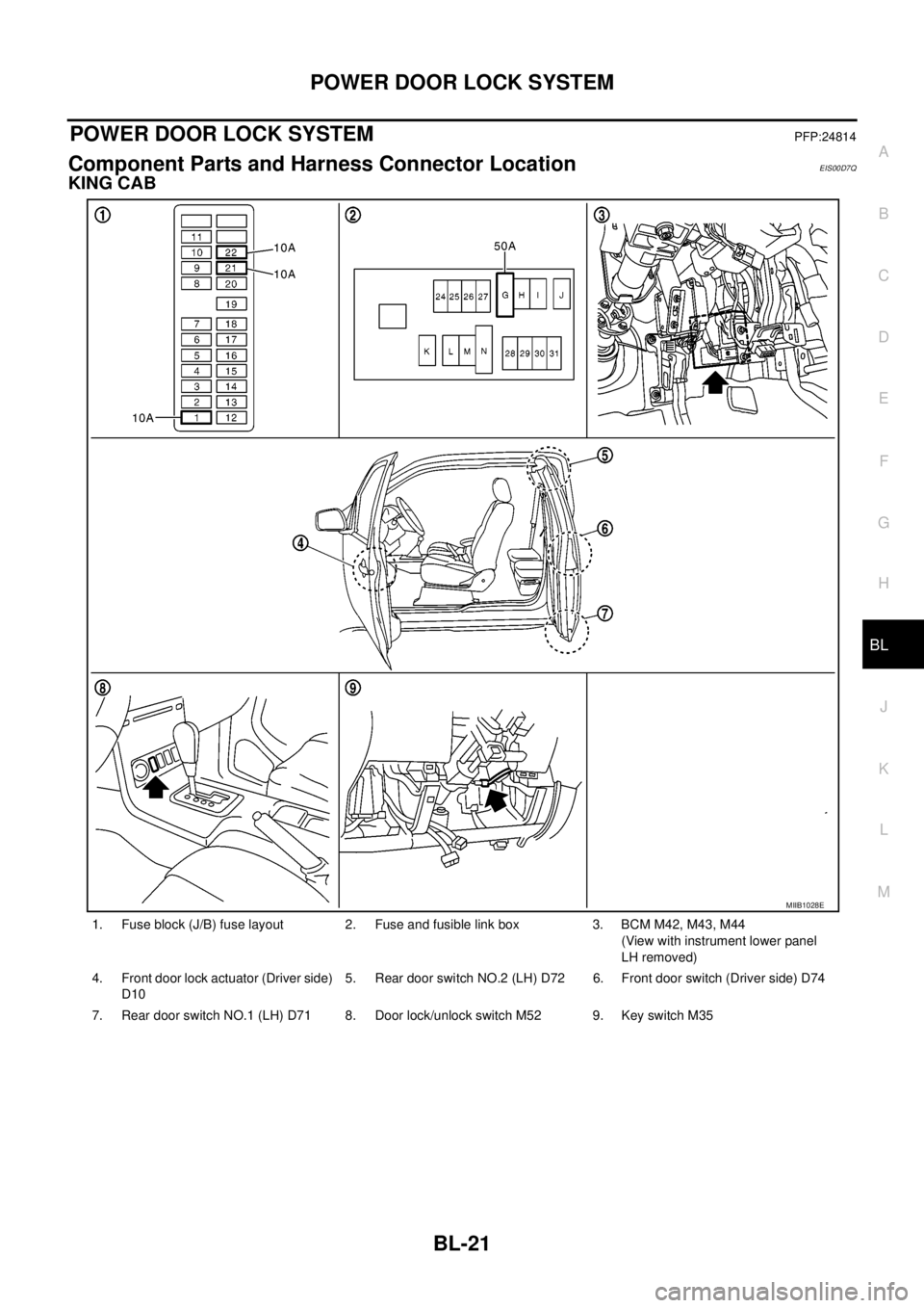
Component Parts and Harness Connector LocationEIS00D7Q
KING CAB
1. Fuse block (J/B) fuse layout 2. Fuse and fusible link box 3. BCM M42, M43, M44
(View with instrument lower panel
LH removed)
4. Front door lock actuator (Driver side)
D105. Rear door switch NO.2 (LH) D72 6. Front door switch (Driver side) D74
7. Rear door switch NO.1 (LH) D71 8. Door lock/unlock switch M52 9. Key switch M35
MIIB1028E
Page 606 of 3171
BL-22
POWER DOOR LOCK SYSTEM
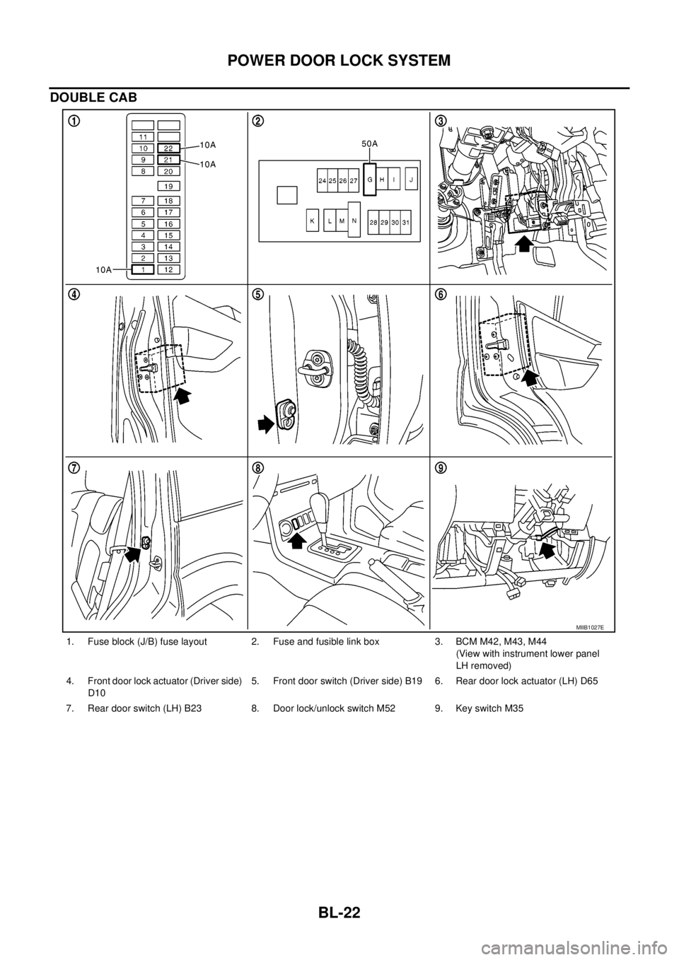
DOUBLE CAB
1. Fuse block (J/B) fuse layout 2. Fuse and fusible link box 3. BCM M42, M43, M44
(View with instrument lower panel
LH removed)
4. Front door lock actuator (Driver side)
D105. Front door switch (Driver side) B19 6. Rear door lock actuator (LH) D65
7. Rear door switch (LH) B23 8. Door lock/unlock switch M52 9. Key switch M35
MIIB1027E
Page 607 of 3171
POWERDOORLOCKSYSTEM
BL-23
C
D
E
F
G
H
J
K
L
MA
B
BL
System DescriptionEIS00D7R
Power is supplied at all times
lthrough 50A fusible link (letterG, located in the fuse and fusible link box)
lto BCM terminal 57
lthrough 10A fuse [No. 21, located in the fuse block (J/B)]
lto BCM terminal 41
lthrough 10A fuse [No. 22, located in the fuse block (J/B)]
lto key switch terminal 2.
When key switch is ON, power is supplied
lthrough key switch terminal 1
lto BCM terminal 5.
When ignition switch is in ON or START position
lthrough 10A fuse [No. 1, located in the fuse block (J/B)]
lto BCM terminal 3.
Ground is supplied
lto BCM terminal 55
lthrough body grounds M21, M80 and M83.
Door switch operation
When front door switch (driver side) is ON (door is OPEN), ground is supplied
lto BCM terminal 15
lthrough front door switch (driver side) terminal 2
lthrough front door switch (driver side) case ground.
When front door switch (passenger side) is ON (door is OPEN), ground is supplied
lto BCM terminal 14
lthrough front door switch (passenger side) terminal 2
lthrough front door switch (passenger side) case ground.
When rear door switch LH is ON (door is OPEN), ground is supplied (Double cab model)
lto BCM terminal 16
lthrough rear door switch LH terminal 2
lthrough rear door switch LH case ground.
When rear door switch RH is ON (door is OPEN), ground is supplied (Double cab model)
lto BCM terminal 12
lthrough rear door switch RH terminal 2
lthrough rear door switch RH case ground.
Key cylinder switch operation (Without multi-remote control system)
When key cylinder is turned to lock position, ground is supplied
lthrough BCM terminal 34
lto key cylinder switch (driver and passenger side) terminals 4
lthrough key cylinder switch (driver and passenger side) terminals 5
lthrough body ground M21, M80 and M83
then all doors are locked.
When key cylinder is turned to unlock position, ground is supplied
lthrough BCM terminal 32
lto key cylinder switch (driver and passenger side) terminal 6
lthrough key cylinder switch (driver and passenger side) terminal 5
lthrough body ground M21, M80 and M83
then all doors are unlocked.
Power door lock operation with door lock/unlock switch
When doors are lock by door lock/unlock switch, ground is supplied
Page 608 of 3171

BL-24
POWER DOOR LOCK SYSTEM
lto BCM terminal 34
lthrough door lock /unlock switch terminals 1 and 3
lthrough body grounds M21, M80 and M83.
then all doors are locked.
When door lock/unlock switch is locked, ground is supplied
lthrough BCM terminal 56
lthrough all door actuators terminal 3
lthrough all door lock actuators terminal 2
lthrough back door lock actuator terminals 1 and 3
lto BCM terminals 54 and 60.
then all doors actuators are locked
Power door unlock operation with door lock/unlock switch
When doors are unlock by door lock/unlock switch, ground is supplied
lto BCM terminal 32
lthrough door lock/unlock switch terminals 2 and 3
lthrough body grounds M21, M80 and M83.
then all doors are locked.
When door lock/unlock switch is unlocked, ground is supplied
lthrough BCM terminals 54 and 60
lthrough all door lock actuators terminal 2
lthrough all door lock actuators terminal 3
lthen all door actuators are unlock
lto BCM terminal 56.
Door lock/unlock switch indicator operation
When door lock/unlock switch is locked, all doors are locked, door lock/unlock switch indicator is on, and
ground is supplied
lto BCM terminal 17
lthrough door lock/unlock switch terminals 5 and 3
lthrough body grounds M21, M80 and M83.
OUTLINE
Function Available by Operating the Door Lock/Unlock Switch
lOperating the door lock/unlock switch to “LOCK” will lock all doors.
lOperating the door lock/unlock switch to “UNLOCK” will unlock all doors.
NOTE:
Unlock via the interior door handles and door lock/unlock switch is always possible.
Door Lock Warning Function
Under following conditions lock actuators will not respond and buzzer warning will beeps while pressing door
lock/unlock switch in LOCK direction.
lIgnition switch is turned OFF
lMechanical key is out of ignition key cylinder
lDoor is opened (except driver side door)
Key Reminder Function
Under following conditions lock actuators will lock the door once, but then immediately unlock all doors and
buzzer warning will beeps while pressing door lock/unlock switch in LOCK direction.
lIgnition switch is turned OFF
lMechanical key is inserted in ignition key cylinder
lDriver side door is opened
Door Lock/Unlock Switch Indicator
The Door lock/unlock switch indicates door lock status. The indicator will illuminates when a lock operation is
accomplish, during this state, if any door is open, the indicator will turn OFF.
Page 609 of 3171
POWERDOORLOCKSYSTEM
BL-25
C
D
E
F
G
H
J
K
L
MA
B
BL
Door lock indicator timer
Door lock indicator timer is designed to reacts and shut down the indicator. The default timer values are 1
minute and 30 minutes.
lWhen the lock operation is activated by keyfob or auto door lock (for further details, refer toBL-92, "Auto
Re-lock Function"), then the illuminate time is set to 1 minute.
lWhen the lock operation is activated by door lock/unlock switch, then the timer is set to 30 minutes.
NOTE:
When the 30 minutes timer is active and ignition switch is turned ON, the indicator illuminate for perma-
nently, unless ignition switch is turned OFF then timer will be reset back to 30 minutes.
CAN Communication System DescriptionEIS00D7T
CAN (Controller Area Network) is a serial communication line for real time application. It is an on-vehicle mul-
tiplex communication line with high data communication speed and excellent error detection ability. Many elec-
tronic control units are equipped onto a vehicle, and each control unit shares information and links with other
control units during operation (not independent). In CAN communication, control units are connected with 2
communication lines (CAN H line, CAN L line) allowing a high rate of information transmission with less wiring.
Each control unit transmits/receives data but selectively reads required data only.
CAN Communication UnitEIS00D7U
Refer toLAN-23, "CAN COMMUNICATION".
Page 618 of 3171
![NISSAN NAVARA 2005 Repair Workshop Manual BL-34
POWER DOOR LOCK SYSTEM
Terminals and Reference Value for BCM
EIS00D7Z
*: Double cab modelTERMI-
NALWIRE
COLORITEM CONDITIONVOLTAGE [V]
(Approx.)
3 Y Ignition switch Ignition switch ON Battery vo NISSAN NAVARA 2005 Repair Workshop Manual BL-34
POWER DOOR LOCK SYSTEM
Terminals and Reference Value for BCM
EIS00D7Z
*: Double cab modelTERMI-
NALWIRE
COLORITEM CONDITIONVOLTAGE [V]
(Approx.)
3 Y Ignition switch Ignition switch ON Battery vo](/manual-img/5/57362/w960_57362-617.png)
BL-34
POWER DOOR LOCK SYSTEM
Terminals and Reference Value for BCM
EIS00D7Z
*: Double cab modelTERMI-
NALWIRE
COLORITEM CONDITIONVOLTAGE [V]
(Approx.)
3 Y Ignition switch Ignition switch ON Battery voltage
5RKeyswitchKey switch ON Battery voltage
Key switch OFF 0
12 L Rear door switch RH* ON (Door is opened)®OFF (Door is closed) 0®Battery voltage
14 LGFront door switch
(Passenger side)ON (Door is opened)®OFF (Door is closed) 0®Battery voltage
15 SBFront door switch
(Driver side)ON (Door is opened)®OFF (Door is closed) 0®Battery voltage
16 P Rear door switch LH* ON (Door is opened)®OFF (Door is closed) 0®Battery voltage
17 WDoor lock/unlock switch indi-
catorAll door closedLock operation
(Illuminates)Battery voltage
Other than above 0
21 P CAN-L — —
22 L CAN-H — —
32 GR Door lock/unlock switch All door closedUnlock 0
Other than above 5
34 O Door lock/unlock switch All door closedLock 0
Other than above 5
41 YPower switch
(Fuse)— Battery voltage
54 GPassenger and rear door lock
actuators*1 (unlock)Door lock/unlock switch (Free®Lock) 0®Battery voltage®0
55 B Ground — 0
56 V All door lock actuators (lock) Door lock/unlock switch (Free®Lock) 0®Battery voltage®0
57 WPower source
(Fusible link)— Battery voltage
60 GDriver door lock actuator
(unlock)Door lock/unlock switch (Free®Lock) 0®Battery voltage®0
Page 620 of 3171
BL-36
POWER DOOR LOCK SYSTEM
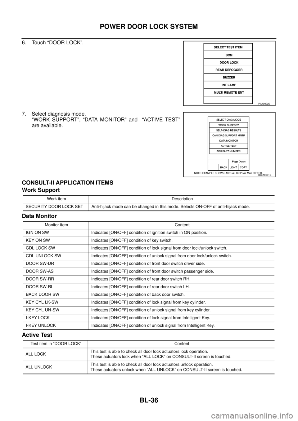
6. Touch “DOOR LOCK”.
7. Select diagnosis mode.
“WORK SUPPORT”, “DATA MONITOR” and “ACTIVE TEST”
are available.
CONSULT-II APPLICATION ITEMS
Work Support
Data Monitor
Active Test
PIIA9922E
BCIA0031E
Work item Description
SECURITY DOOR LOCK SET Anti-hijack mode can be changed in this mode. Selects ON-OFF of anti-hijack mode.
Monitor item Content
IGN ON SW Indicates [ON/OFF] condition of ignition switch in ON position.
KEY ON SW Indicates [ON/OFF] condition of key switch.
CDL LOCK SW Indicates [ON/OFF] condition of lock signal from door lock/unlock switch.
CDL UNLOCK SW Indicates [ON/OFF] condition of unlock signal from door lock/unlock switch.
DOOR SW-DR Indicates [ON/OFF] condition of front door switch driver side.
DOOR SW-AS Indicates [ON/OFF] condition of front door switch passenger side.
DOOR SW-RR Indicates [ON/OFF] condition of rear door switch RH.
DOOR SW-RL Indicates [ON/OFF] condition of rear door switch LH.
BACK DOOR SW Indicates [ON/OFF] condition of back door switch.
KEY CYL LK-SW Indicates [ON/OFF] condition of lock signal from key cylinder.
KEY CYL UN-SW Indicates [ON/OFF] condition of unlock signal from key cylinder.
I-KEY LOCK Indicates [ON/OFF] condition of lock signal from Intelligent Key.
I-KEY UNLOCK Indicates [ON/OFF] condition of unlock signal from Intelligent Key.
Test item in “DOOR LOCK” Content
ALL LOCKThis test is able to check all door lock actuators lock operation.
These actuators lock when “ALL LOCK” on CONSULT-II screen is touched.
ALL UNLOCKThis test is able to check all door lock actuators unlock operation.
These actuators unlock when “ALL UNLOCK” on CONSULT-II screen is touched.