2005 MITSUBISHI LANCER weight
[x] Cancel search: weightPage 141 of 788

Page 147 of 788

Page 148 of 788

DRIVE SHAFT ASSEMBLY
FRONT AXLE26-16
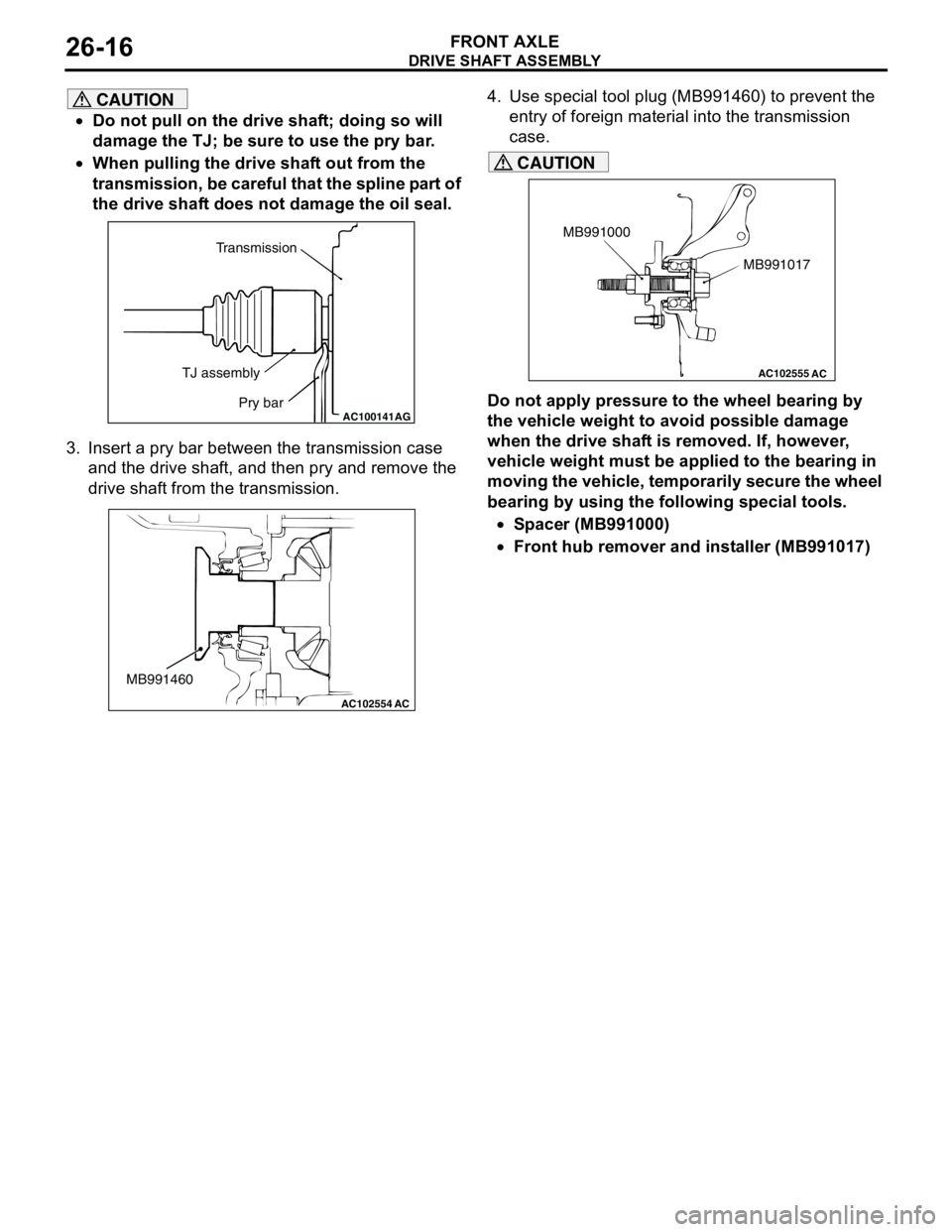
CAUTION
•Do not pull on the drive shaft; doing so will
damage the TJ; be sure to use the pry bar.
•When pulling the drive shaft out from the
transmission, be careful that the spline part of
the drive shaft does not damage the oil seal.
3. Insert a pry bar between the transmission case
and the drive shaft, and then pry and remove the
drive shaft from the transmission.4. Use special tool plug (MB991460) to prevent the
entry of foreign material into the transmission
case.
CAUTION
Do not apply pressure to the wheel bearing by
the vehicle weight to avoid possible damage
when the drive shaft is removed. If, however,
vehicle weight must be applied to the bearing in
moving the vehicle, temporarily secure the wheel
bearing by using the following special tools.
•Spacer (MB991000)
•Front hub remover and installer (MB991017)AC100141
Transmission
TJ assembly
Pry bar
AG
AC102554
MB991460
AC
AC102555
AC
MB991017 MB991000
Page 162 of 788

Page 166 of 788

TROUBLESHOOTING
WHEEL AND TYRE31-4
WHEEL BALANCE ACCURACYM1311001700247
PURPOSE
This section contains tips and procedures for
achieving accurate wheel balance. Steering wheel
vibration and/or body shake can result if any of these
procedures are not carefully observed.
1. Wheels and tyres must be properly mounted on a
balancer in order to achieve correct balance.
Centring the wheel on the shaft of the balancer is
essential for proper mounting.
2. Off-the-car wheel balancers must be calibrated
periodically to ensure good balancing results. An
inaccurately calibrated balancer could cause
unnecessary replacement of tyres, shocks,
suspension components, or steering components.
Check your balancer's calibration approximately
every 100 balances. Your wheel balancer's
instruction manual should include calibration
procedures. If the calibration procedures specifically
for your balancer are missing, use the generic steps
in this section for zero calibration, static balance, and
dynamic balance checks. The wheel balancer
calibration checks are also described in the
flowchart. (Refer to P.31-6).
PROCEDURE
1. Confirm that the balancer's cone and the wheel
mounting cone are undamaged and free of dirt
and rust.
2. On this vehicle, the wheel's centre hole on the
hub side has a chamfered edge. Use a
back-mounting cone on your wheel balancer to
centre the wheel on the balancer shaft.
3. Install a wheel mounting cone. The appropriate
size cone for this vehicle is 67.0 mm.
4. Before balancing the wheel, remove any wheel
weights from both sides. Also check both sides for
any damage.
5. When installing wheel weights, hammer them at a
straight (not diagonal) angle. Scalloped
wearLack of rotation of tyres or worn
or out-of-alignment suspensionRotate the tyres, and
check the front or
rear suspension
alignments.
Refer to GROUP
33, On-vehicle
service − Front
wheel alignment
check and
adjustment P.33-5.
Refer to GROUP
34, On-vehicle
service − Rear
wheel alignment
check and
adjustment P.34-5. Symptom Probable cause Remedy Reference page
ACX00934
Page 167 of 788

TROUBLESHOOTING
WHEEL AND TYRE31-5
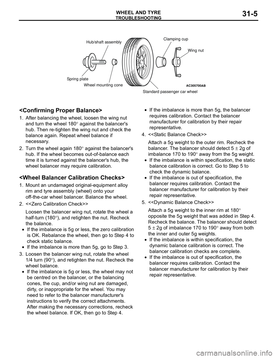
1. After balancing the wheel, loosen the wing nut
and turn the wheel 180° against the balancer's
hub. Then re-tighten the wing nut and check the
balance again. Repeat wheel balance if
necessary.
2. Turn the wheel again 180° against the balancer's
hub. If the wheel becomes out-of-balance each
time it is turned against the balancer's hub, the
wheel balancer may require calibration.
1. Mount an undamaged original-equipment alloy
rim and tyre assembly (wheel) onto your
off-the-car wheel balancer. Balance the wheel.
2. <
Loosen the balancer wing nut, rotate the wheel a
half-turn (180°), and retighten the nut. Recheck
the balance.
•If the imbalance is 5g or less, the zero calibration
is OK. Rebalance the wheel, then go to Step 4 to
check static balance.
•If the imbalance is more than 5g, go to Step 3.
3. Loosen the balancer wing nut, rotate the wheel
1/4 turn (90°), and retighten the nut. Recheck the
wheel balance.
•If the imbalance is 5g or less, the wheel may not
be centred on the balancer, or the balancing
cones, the cup, and/or wing nut are damaged,
dirty, or inappropriate for the wheel. You may
need to refer to the balancer manufacturer's
instructions to verify the correct attachments.
After making the necessary corrections, recheck
the wheel balance. If OK, then go to Step 4.•If the imbalance is more than 5g, the balancer
requires calibration. Contact the balancer
manufacturer for calibration by their repair
representative.
4. <
Attach a 5g weight to the outer rim. Recheck the
balancer. The balancer should detect 5 ± 2g of
imbalance 170 to 190° away from the 5g weight.
•If the imbalance is within specification, the static
balance calibration is correct. Go to Step 5 to
check the dynamic balance.
•If the imbalance is out of specification, the
balancer requires calibration. Contact the
balancer manufacturer for calibration by their
repair representative.
5. <
Attach a 5g weight to the inner rim at 180°
opposite the 5g weight that was added in Step 4.
Recheck the balance. The balancer should detect
5 ± 2g of imbalance 170 to 190° away from both
the inner and outer 5g weights.
•If the imbalance is within specification, the
dynamic balance calibration is correct. The
balancer calibration checks are complete.
•If the imbalance is out of specification, the
balancer requires calibration. Contact the
balancer manufacturer for calibration by their
repair representative.
AC305700AB
Hub/shaft assemblyClamping cup
Wing nut
Standard passenger car wheel Wheel mounting cone Spring plate
Page 168 of 788

TROUBLESHOOTING
WHEEL AND TYRE31-6
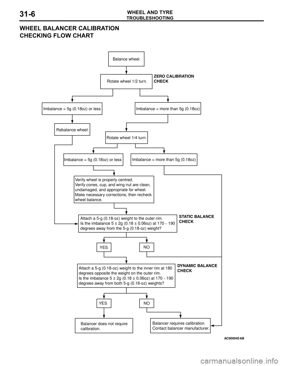
WHEEL BALANCER CALIBRATION
CHECKING FLOW CHART
AC000040
Balance wheel.
Rotate wheel 1/2 turn.
Imbalance = 5g (0.18oz) or lessImbalance = more than 5g (0.18oz)
Rebalance wheel.
Rotate wheel 1/4 turn.
Imbalance = 5g (0.18oz) or lessImbalance = more than 5g (0.18oz)
Verify wheel is properly centred.
Verify cones, cup, and wing nut are clean,
undamaged, and appropriate for wheel.
Make necessary corrections, then recheck
wheel balance.
Attach a 5-g (0.18-oz) weight to the outer rim.
Is the imbalance 5 ± 2g (0.18 ± 0.06oz) at 170
– 190
degrees away from the 5-g (0.18-oz) weight?
YESNO
Attach a 5-g (0.18-oz) weight to the inner rim at 180
degrees opposite the weight on the outer rim.
Is the imbalance 5 ± 2g (0.18 ± 0.06oz) at 170
– 190
degrees away from both 5-g (0.18-oz) weights?
YES NO
Balancer does not require
calibration.Balancer requires calibration.
Contact balancer manufacturer.ZERO CALIBRATION
CHECK
STATIC BALANCE
CHECK
DYNAMIC BALANCE
CHECK
AB
Page 174 of 788

ENGINE MOUNTING
POWER PLANT MOUNT32-4
ENGINE MOUNTING
REMOVAL AND INSTALLATIONM1321001100440
CAUTION
*: Indicates parts which should be initially tightened, and then fully tightened after placing the vehicle
horizontally and loading the full weight of the engine on the vehicle body.
Pre-removal Operation
Raise the engine and transmission assembly until its weight
is not applied to the insulator, and support it securely.
AC303999AC303968AC304304
AB
<4G1> <4G6>
44 ± 10 N·m*
67 ± 7 N·m*
2N
3
44 ± 10 N·m*
67 ± 7 N·m*
2N
3
12 ± 2 N·m
1
Removal steps
1. Pressure hose clamp <4G6>2. Self-locking nuts
3. Engine front mounting bracketRemoval steps (Continued)