2005 MITSUBISHI LANCER charging
[x] Cancel search: chargingPage 81 of 788
CHARGING SYSTEM
ENGINE ELECTRICAL16-17
>>B<< ROTOR INSTALLATION
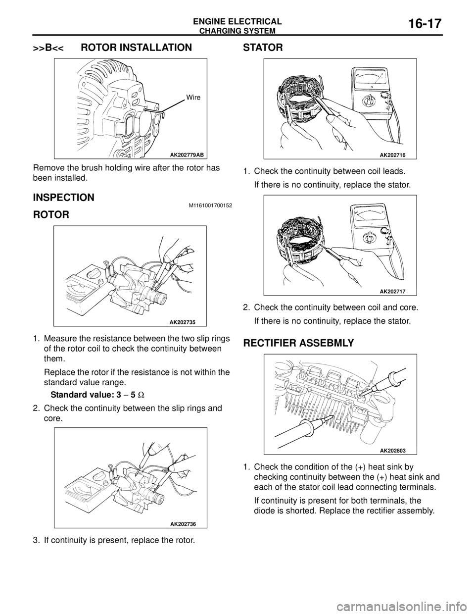
Remove the brush holding wire after the rotor has
been installed.
INSPECTION M1161001700152
ROTOR
1. Measure the resistance between the two slip rings
of the rotor coil to check the continuity between
them.
Replace the rotor if the resistance is not within the
standard value range.
Standard value: 3 − 5 Ω
2. Check the continuity between the slip rings and
core.
3. If continuity is present, replace the rotor.
STATOR
1. Check the continuity between coil leads.
If there is no continuity, replace the stator.
2. Check the continuity between coil and core.
If there is no continuity, replace the stator.
RECTIFIER ASSEBMLY
1. Check the condition of the (+) heat sink by
checking continuity between the (+) heat sink and
each of the stator coil lead connecting terminals.
If continuity is present for both terminals, the
diode is shorted. Replace the rectifier assembly.
AK202779
Wire
AB
AK202735
AK202736
AK202716
AK202717
AK202803
Page 82 of 788
CHARGING SYSTEM
ENGINE ELECTRICAL16-18
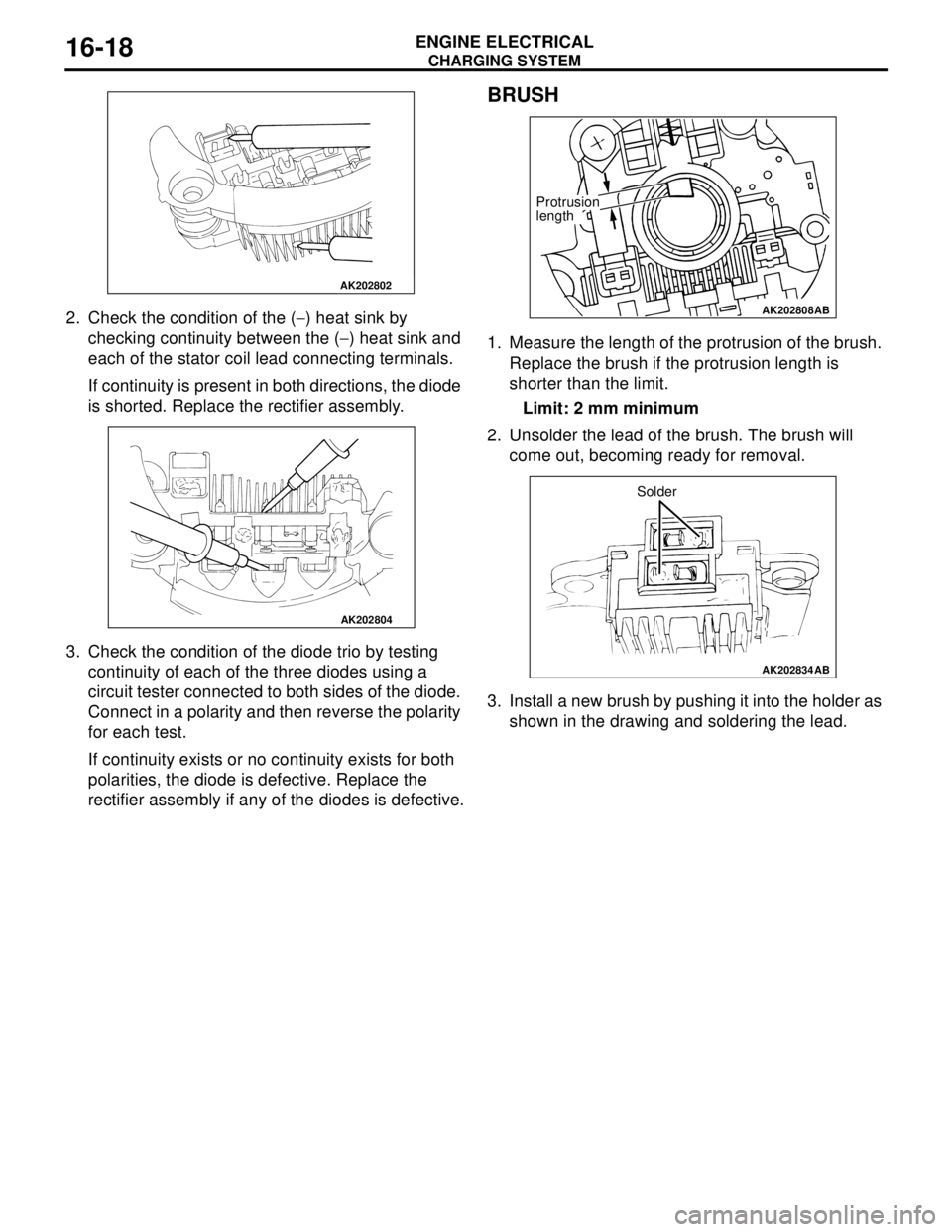
2. Check the condition of the (−) heat sink by
checking continuity between the (−) heat sink and
each of the stator coil lead connecting terminals.
If continuity is present in both directions, the diode
is shorted. Replace the rectifier assembly.
3. Check the condition of the diode trio by testing
continuity of each of the three diodes using a
circuit tester connected to both sides of the diode.
Connect in a polarity and then reverse the polarity
for each test.
If continuity exists or no continuity exists for both
polarities, the diode is defective. Replace the
rectifier assembly if any of the diodes is defective.
BRUSH
1. Measure the length of the protrusion of the brush.
Replace the brush if the protrusion length is
shorter than the limit.
Limit: 2 mm minimum
2. Unsolder the lead of the brush. The brush will
come out, becoming ready for removal.
3. Install a new brush by pushing it into the holder as
shown in the drawing and soldering the lead.
AK202802
AK202804
AK202808
Protrusion
length
AB
AK202834
Solder
AB
Page 389 of 788
54A-1
GROUP 54A
CHASSIS
ELECTRICAL
CONTENTS
BATTERY. . . . . . . . . . . . . . . . . .
54A-4
SERVICE SPECIFICATIONS. . . . .
54A-4
ON-VEHICLE SERVICE. . . . . . . . .54A-4
FLUID LEVEL AND SPECIFIC
GRAVITY CHECK . . . . . . . . . . . . . . . . . 54A-4
CHARGING . . . . . . . . . . . . . . . . . . . . . . 54A-4
BATTERY TEST . . . . . . . . . . . . . . . . . . 54A-5
IGNITION SWITCH* . . . . . . . . . .54A-6
GENERAL INFORMATION . . . . . .
54A-6
SPECIAL TOOLS. . . . . . . . . . . . . .54A-8
TROUBLESHOOTING . . . . . . . . . .54A-9
IGNITION KEY REMINDER BUZZER AND
DOOR LOCK PREVENTION FUNCTION
TROUBLESHOOTING . . . . . . . . . . . . . . 54A-9
IMMOBILIZER SYSTEM
TROUBLESHOOTING . . . . . . . . . .
54A-9
DIAGNOSIS CODE CHART . . . . . . . . . . 54A-9
DIAGNOSTIC TROUBLE CODE
PROCEDURES . . . . . . . . . . . . . . . .
54A-10
SYMPTOM CHART. . . . . . . . . . . . .54A-11
SYMPTOM PROCEDURES . . . . . .54A-12
DATA LIST REFERENCE TABLE .54A-19
CHECK IMMOBILIZER-ECU . . . . .54A-19
ON-VEHICLE SERVICE . . . . . . . . .54A-20
HOW TO REGISTER ENCRYPTED
CODE . . . . . . . . . . . . . . . . . . . . . . . . . . . 54A-20
IGNITION SWITCH . . . . . . . . . . . . . . . . 54A-27
REMOVAL AND INSTALLATION . . . . . . 54A-27
INSPECTION . . . . . . . . . . . . . . . . . . . . . 54A-28
Continued on next page
WARNINGS REGARDING SERVICING OF SUPPLEMENTAL RESTRAINT SYSTEM (SRS) EQUIPPED VEHICLES
WARNING
•Improper service or maintenance of any component of the SRS, or any SRS-related component, can lead to
personal injury or death to service personnel (from inadvertent firing of the air bag) or to the driver and
paassenger (from rendering the SRS inoperative).
•Service or maintenance of any SRS component or SRS-related component must be performed only at an
authorized MITSUBISHI dealer.
•MITSUBISHI dealer personnel must thoroughly review this manual, and especially its GROUP 52B - Supplemental
Restraint System (SRS) before beginning any service or maintenance of any component of the SRS or any
SRS-related component.
NOTE
The SRS includes the following components: SRS air bag control unit, SRS warning light, front impact sensors, air bag module,
clock spring, and interconnecting wiring. Other SRS-related components (that may have to be removed/installed in connection
with SRS service or maintenance) are indicated in the table of contents by an asterisk (*).
Page 392 of 788
BATTERY
CHASSIS ELECTRICAL54A-4
BATTERY
SERVICE SPECIFICATIONSM1541000300209
ON-VEHICLE SERVICE
FLUID LEVEL AND SPECIFIC GRAVITY
CHECK
M1541001000438
CAUTION
•If the battery fluid is below the LOWER
LEVEL, the battery could explode in using.
•If the battery fluid is over the UPPER LEVEL,
leakage could result.
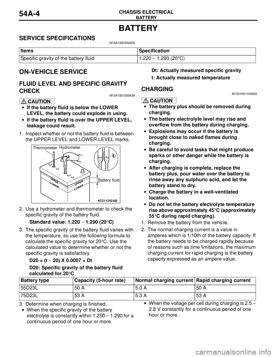
1. Inspect whether or not the battery fluid is between
the UPPER LEVEL and LOWER LEVEL marks.
2. Use a hydrometer and thermometer to check the
specific gravity of the battery fluid.
Standard value: 1.220 − 1.290 (20°C)
3. The specific gravity of the battery fluid varies with
the temperature, so use the following formula to
calculate the specific gravity for 20°C. Use the
calculated value to determine whether or not the
specific gravity is satisfactory.
D20 = (t − 20) X 0.0007 + Dt
D20: Specific gravity of the battery fluid
calculated for 20°CDt: Actually measured specific gravity
t: Actually measured temperature
CHARGINGM1541001100509
CAUTION
•The battery plus should be removed during
charging.
•The battery electrolyte level may rise and
overflow from the battery during charging.
•Explosions may occur if the battery is
brought close to naked flames during
charging.
•Be careful to avoid tasks that might produce
sparks or other danger while the battery is
charging.
•After charging is complete, replace the
battery plus, pour water over the battery to
rinse away any sulphuric acid, and let the
battery stand to dry.
•Charge the battery in a well-ventilated
location.
•Do not let the battery electrolyte temperature
rise above approximately 45°C (approximately
55°C during rapid charging).
1. Remove the battery from the vehicle.
2. The normal charging current is a value in
amperes which is 1/10th of the battery capacity. If
the battery needs to be charged rapidly because
of reasons such as time limitations, the maximum
charging current for rapid charging is the battery
capacity expressed as an ampere value.
3. Determine when charging is finished.
•When the specific gravity of the battery
electrolyte is constantly within 1.250 − 1.290 for a
continuous period of one hour or more.•When the voltage per cell during charging is 2.5 −
2.8 V constantly for a continuous period of one
hour or more. Items Specification
Specific gravity of the battery fluid 1.220 − 1.290 (20°C)
AC211242AB
Battery fluid ThermometerHydrometer
Battery type Capacity (5-hour rate) Normal charging current Rapid charging current
55D23L 50 A 5.0 A 50 A
75D23L 53 A 5.3 A 53 A
Page 393 of 788
BATTERY
CHASSIS ELECTRICAL54A-5
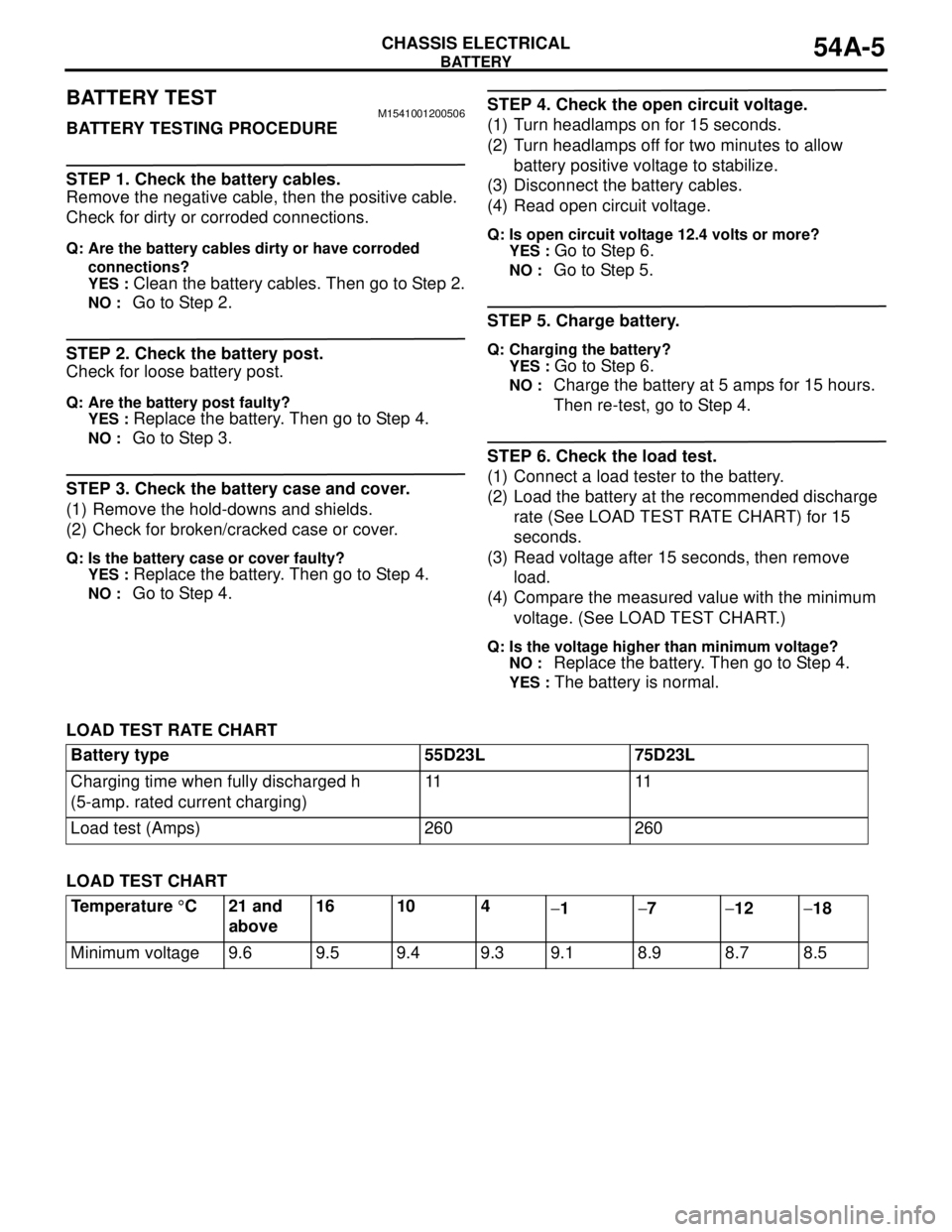
BATTERY TESTM1541001200506
BATTERY TESTING PROCEDURE
STEP 1. Check the battery cables.
Remove the negative cable, then the positive cable.
Check for dirty or corroded connections.
Q: Are the battery cables dirty or have corroded
connections?
YES :
Clean the battery cables. Then go to Step 2.
NO : Go to Step 2.
STEP 2. Check the battery post.
Check for loose battery post.
Q: Are the battery post faulty?
YES :
Replace the battery. Then go to Step 4.
NO : Go to Step 3.
STEP 3. Check the battery case and cover.
(1) Remove the hold-downs and shields.
(2) Check for broken/cracked case or cover.
Q: Is the battery case or cover faulty?
YES :
Replace the battery. Then go to Step 4.
NO : Go to Step 4.
STEP 4. Check the open circuit voltage.
(1) Turn headlamps on for 15 seconds.
(2) Turn headlamps off for two minutes to allow
battery positive voltage to stabilize.
(3) Disconnect the battery cables.
(4) Read open circuit voltage.
Q: Is open circuit voltage 12.4 volts or more?
YES :
Go to Step 6.
NO : Go to Step 5.
STEP 5. Charge battery.
Q: Charging the battery?
YES :
Go to Step 6.
NO : Charge the battery at 5 amps for 15 hours.
Then re-test, go to Step 4.
STEP 6. Check the load test.
(1) Connect a load tester to the battery.
(2) Load the battery at the recommended discharge
rate (See LOAD TEST RATE CHART) for 15
seconds.
(3) Read voltage after 15 seconds, then remove
load.
(4) Compare the measured value with the minimum
voltage. (See LOAD TEST CHART.)
Q: Is the voltage higher than minimum voltage?
NO :
Replace the battery. Then go to Step 4.
YES : The battery is normal.
LOAD TEST RATE CHART
LOAD TEST CHARTBattery type 55D23L 75D23L
Charging time when fully discharged h
(5-amp. rated current charging)11 11
Load test (Amps) 260 260
Temperature °C 21 and
above16 10 4
−1−7−12−18
Minimum voltage 9.6 9.5 9.4 9.3 9.1 8.9 8.7 8.5
Page 486 of 788

55-2
ON-VEHICLE SERVICE . . . . . . . . . . .55-69
SIGHT GLASS REFRIGERANT
LEVEL TEST . . . . . . . . . . . . . . . . . . . . . . . . 55-69
MAGNETIC CLUTCH TEST . . . . . . . . . . . . 55-69
COMPRESSOR DRIVE BELT
ADJUSTMENT . . . . . . . . . . . . . . . . . . . . . . 55-69
DUAL PRESSURE SWITCH CHECK . . . . . 55-69
CHARGING . . . . . . . . . . . . . . . . . . . . . . . . . 55-70
CORRECTING LOW REFRIGERANT LEVEL
IN CASE THE SERVICE CAN IN USED. . . 55-72
DISCHARGING SYSTEM . . . . . . . . . . . . . . 55-72
REFILLING OF OIL IN THE A/C
SYSTEM . . . . . . . . . . . . . . . . . . . . . . . . . . . 55-72
PERFORMANCE TEST . . . . . . . . . . . . . . . 55-73
REFRIGERANT LEAK REPAIR
PROCEDURE . . . . . . . . . . . . . . . . . . . . . . . 55-74
COMPRESSOR NOISE CHECK . . . . . . . . 55-74
POWER RELAY CHECK . . . . . . . . . . . . . . 55-75
IDLE-UP OPERATION CHECK . . . . . . . . . 55-76
CLEAN AIR FILTER REPLACEMENT
PROCEDURE . . . . . . . . . . . . . . . . . . . . . . . 55-76
HEATER CONTROL ASSEMBLY AND A/C
SWITCH . . . . . . . . . . . . . . . . . . . . . . .55-77
REMOVAL AND INSTALLATION . . . . . . . . 55-77
INSPECTION . . . . . . . . . . . . . . . . . . . . . . . 55-79
DISASSEMBLY AND REASSEMBLY . . . . . 55-79
HEATER UNIT, HEATER CORE,
BLOWER ASSEMBLY AND
EVAPORATOR UNIT* . . . . . . . . . . . .55-81
REMOVAL AND INSTALLATION . . . . . . . . 55-81
HEATER UNIT . . . . . . . . . . . . . . . . . . . . . . 55-82
DISASSEMBLY AND REASSEMBLY
DISASSEMBLY AND ASSEMBLY
BLOWER ASSEMBLY . . . . . . . . . . . . . . . . 55-84
DISASSEMBLY AND REASSEMBLY . . . . . 55-84
BLOWERMOTOR, RESISTOR AND
OUTSIDE/INSIDE AIR SELECTION
DAMPER CONTROL MOTOR . . . . . .55-85
REMOVAL AND INSTALLATION . . . . . . . . 55-85
INSPECTION . . . . . . . . . . . . . . . . . . . . . . . . 55-86
EVAPORATOR ASSEMBLY . . . . . . .55-88
REMOVAL AND INSTALLATION
REMOVAL AND INSTALLATION
INSPECTION . . . . . . . . . . . . . . . . . . . . . . . . 55-90
COMPRESSOR ASSEMBLY AND
TENSION PULLEY . . . . . . . . . . . . . . .55-91
REMOVAL AND INSTALLATION . . . . . . . . 55-91
INSPECTION . . . . . . . . . . . . . . . . . . . . . . . . 55-93
DISASSEMBLY AND REASSEMBLY . . . . . 55-94
INSPECTION . . . . . . . . . . . . . . . . . . . . . . . . 55-95
CONDENSER AND CONDENSER
FAN MOTOR . . . . . . . . . . . . . . . . . . . .55-96
REMOVAL AND INSTALLATION . . . . . . . . 55-96
INSPECTION . . . . . . . . . . . . . . . . . . . . . . . . 55-97
REFRIGERANT LINE . . . . . . . . . . . . .55-98
REMOVAL AND INSTALLATION
REMOVAL AND INSTALLATION
DUCTS . . . . . . . . . . . . . . . . . . . . . . . .55-101
REMOVAL AND INSTALLATION . . . . . . . . 55-101
VENTILATORS . . . . . . . . . . . . . . . . . .55-102
REMOVAL AND INSTALLATION . . . . . . . . 55-102
Page 554 of 788

ON-VEHICLE SERVICE
HEATER, AIR CONDITIONER AND VENTILATION55-70
CHARGING M1552001200362
1. With the handles turned back all the way (valve
closed), install the adaptor valve to the
low-pressure side of the gauge manifold.
2. Connect the charging hose (blue) to the adaptor
valve.
3. Connect the quick joint (for low-pressure) to the
charging hose (blue).
CAUTION
•Use tools that are suited to R134a.
•To install the quick joint, press section when
connecting, run your hand along the hose
while pressing to ensure that there are no
bends in the hose.
4. Connect the quick joint (for low-pressure) to the
low- pressure service valve.
NOTE: The low-pressure service valve should be
connected to the flexible suction hose.5. Close the high and low-pressure valves of the
gauge manifold.
CAUTION
Be sure to connect the power plug of the vacuum
pump to the vacuum pump adapter, and then
connect the power plug of the adapter to a 100-V
outlet.
6. Install the vacuum pump adaptor to the vacuum
pump.
7. Connect the charging hose (yellow) to the R-134a
connection port of the vacuum pump adaptor.
8. Tighten the adaptor valve handle (valve open).
9. Open the low-pressure valve of the gauge
manifold.
10.Turn the power switch of the vacuum pump to the
ON position.
NOTE: Even if the vacuum pump power switch is
turned ON, the vacuum pump will not operate
because of the power supply connection in step
(6).
CAUTION
Do not operate the compressor for evacuation.
11.Turn the vacuum pump adaptor switch to the
R134a side to start the vacuum pump.
12.Evacuate to a vacuum reading of 100 kPa or
higher (takes approx. 10 minutes).
AC212526
AB
A
Sleeve Low-pressure
service valve Quick
joint
(for low
pressure)
SwitchVacuum
pump
Power supply
plug Vacuum
pump
adaptor R-12
connection
portCharging hose
(blue)
Adapter
valveCharging hose
(yellow)Gauge manifold
Switch
R-134a
connection
port Low-pressure
valveHigh-pressure
valve
AC212535
Vacuum
pump Low-pressure
service valve
AB
Vacuum pump
adaptor switch
Page 555 of 788

ON-VEHICLE SERVICE
HEATER, AIR CONDITIONER AND VENTILATION55-71
CAUTION
Do not operate the compressor in the vacuum
condition; damage may occur.
13.Loosen the valve of the adapter valve fully (valve
closed), and turn off the vacuum pump adapter
switch. Then leave it for five minutes.
14.Check the system for proper sealing (negative
pressure should not decrease).
15.Connect the service can valve to the service can
with the handle loosened fully (valve closed).
16.Turn the handle of the adaptor valve back all the
way (valve closed), remove it from the gauge
manifold and install the service can.
17.Tighten the handle of the charging valve (valve
closed) to puncture the service can.
CAUTION
If the service can is inverted, liquid refrigerant
may be drawn into the compressor damaging it
by liquid compression. Keep the service can
upright to ensure that refrigerant is charged in
gas state.
18.Turn the handle of the charging valve back (valve
open) and tighten the handle of the adaptor valve
(valve open) to charge the system with refrigerant.
19.If the refrigerant is not drawn in, turn the handle of
the adaptor valve back all the way (valve closed).
20.Check for gas leaks using a leak detector. If a gas
leak is detected, re-tighten the connections, and
then repeat the charging procedure from
evacuation in step (11).
CAUTION
The leak detector for R-134a should be used.
21.Start the engine.
22.Operate the A/C and set to the lowest
temperature (MAX. COOL).
23.Fix the engine speed at 1,500 r/min.
CAUTION
If the service can is inverted, liquid refrigerant
may be drawn into the compressor damaging it
by liquid compression. Keep the service can
upright to ensure that refrigerant is charged in
gas state.
24.Tighten the handle of the adaptor valve (valve
open) to charge the required volume of
refrigerant.
AC212536
Valve open
Valve close
Charging valve
Service can Adaptor valve
AB
AC212537
Charging valve
Service can
(Refrigerant container)
Low-pressure
service valve
AB